- Step 1: Pre-Installation Preparations
- Step 2: Safety Considerations
- How to install a vibration sensor?
- Step 3: Mechanical Installation
- Where should a vibration sensor be placed?
- Step 4: Electrical Installation
- Step 5: Configuration and Calibration
- What is the setting of vibration probe?
- Step 6: Functional Testing and Verification
- Step 7: Environmental Considerations
- Step 8: Compliance with Standards
- Step 9: Final Additional Checkpoints
- Step 10: Handover, Final Checks and Commissioning
- Downloadable Installation and Commissioning Checklist for Vibration Proximity Probe
Vibration proximity monitors are crucial in ensuring the safe operation of rotating machinery in continuous process plants. Proper installation and commissioning of these monitors help in early detection of faults, preventing catastrophic failures and unplanned downtime. This method statement outlines a step-by-step procedure for the installation of vibration proximity monitors, including an installation checklist for seamless implementation.
Step 1: Pre-Installation Preparations
Review Documentation
- Gather all relevant documents, such as equipment manuals, Piping & Instrumentation Diagram (P&ID), Instrument Data Sheet /Specification, Instrument Hook-Up Diagrams, and Instrument Loop Diagrams. This will assist in ensuring that the control systems of the plant are properly integrated.
- Verify the instrument against the specification sheet to ensure compatibility with site requirements.
Inventory Check
- Ensure all components, including vibration probes, connectors, mounting hardware, and proximitor are available and accounted for.
- Confirm that all instruments are calibrated and certified, and that are set per the equipment specifications.
Site Assessment
- Perform a site assessment to confirm compliance with environmental and operational requirements.
- Check for potential interference and ensure maintenance accessibility at the installation site.
Planning
- Develop an installation plan detailing task sequences, required resources, and timelines.
- Assign roles and responsibilities to team members for efficient task execution.
Step 2: Safety Considerations
Personal Protective Equipment (PPE)
- Ensure that all personnel involved in the installation and functional testing wear appropriate PPE, including helmets, gloves, safety goggles, and ear protection.
- PPE is essential for protection against potential hazards like flying debris, electrical shock, or loud noise.
Hazard Assessment
- Conduct a thorough hazard assessment of the work area to identify any risks associated with the installation and testing process.
- Notify every team member of any potential hazards that have been found, and then take the necessary precautions, such enclosing the area with a fence, posting warning signs, or installing more safety barriers.
Lockout/Tagout (LOTO) Procedures
- Adhere to LOTO procedures to safely shut down and de-energize the equipment involved in the testing process. This step ensures that machinery cannot be inadvertently restarted during installation or testing.
- Use lockout devices to isolate energy sources and attach tags to indicate that the machinery should not be operated until the testing is complete.
Emergency Procedures
- Establish emergency procedures, including clearly marked evacuation routes and accessible first aid stations. All personnel should be briefed on these procedures before starting the installation.
- Ensure that emergency contacts, such as on-site medical personnel and safety officers, are readily available.
Permit System
- Implement a permit-to-work system to control and document the work being done, particularly if the installation occurs in hazardous areas. The permit system helps ensure that all safety measures are in place before work begins.
- Permits should be signed by authorized personnel after confirming that the necessary safety protocols are met, such as LOTO completion, PPE checks, and hazard mitigations.
How to install a vibration sensor?
Step 3: Mechanical Installation
Mounting Proximitor Sensors
- Begin by inspecting the vibration probe, extension cable, and connectors. Look for any signs of physical damage, such as bends, cuts, or wear.
- If any damage is found, replace the affected parts before proceeding with further tests.
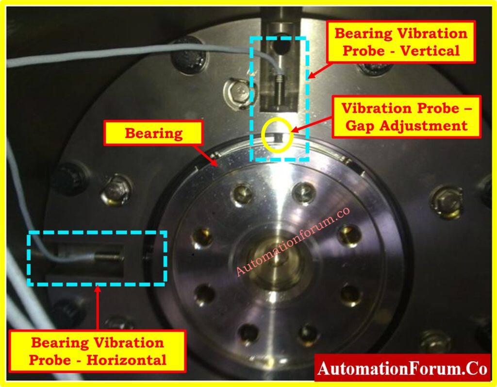
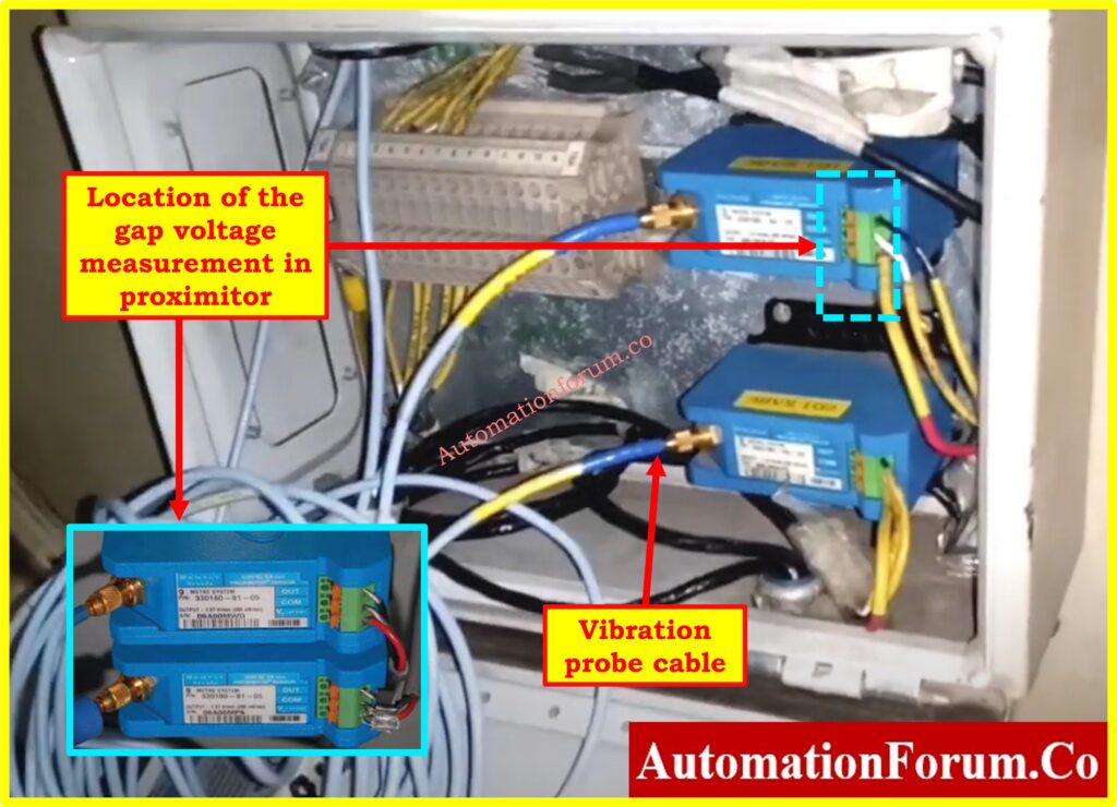
- Identify suitable mounting locations on the equipment and install Proximitor within the specified distances from the monitored components.
- Secure sensors using appropriate brackets and hardware.
Where should a vibration sensor be placed?
Probe Installation
- Ensure the surface where the vibration probe is mounted is clean, smooth, and free from contaminants. Any irregularities on the surface can affect the accuracy of the probe readings.
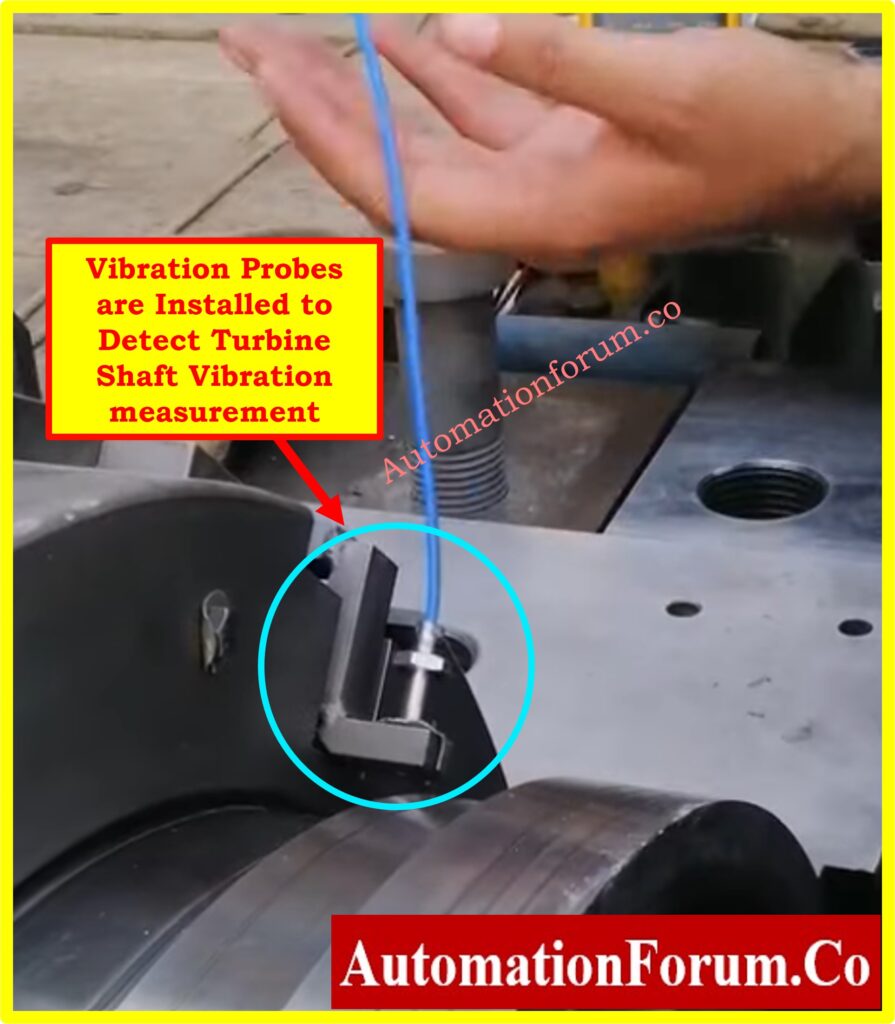
- Consider the equipment’s critical points when selecting probe placement. Probes should be positioned near areas prone to mechanical failure (e.g., bearings, shafts, or couplings).
- Avoid placing probes near high-vibration or resonance areas unless necessary for accurate measurement.
- Where possible, use isolation mounts to minimize the transmission of external vibrations to the probe.
- This ensures that the probes measure only the vibrations of the monitored equipment and not ambient noise or structural resonance.
- Install vibration probes per the manufacturer’s specifications, ensuring correct alignment and that probe gaps are set accurately.
- Confirm that all connections are tight and stable.
Cable Routing
- Route signal cables from probes to the monitoring system, separating low-voltage cables from power wiring to avoid electromagnetic interference.
Step 4: Electrical Installation

Wiring Connections
- Connect signal cables from vibration probes to the monitoring system following electrical drawings.
- Confirm that all connections are tight and secure to prevent signal loss.
- Resistance Check: Using a multimeter, measure the probe’s resistance. It should fall within the specific range (typically 5-9 ohms) according to the manufacturer’s specifications.
- Continuity Check: Measure the extension cable’s resistance, which should generally range from 5 to 20 ohms. Ensure values meet the required standards to prevent signal loss.
Power Supply Connection
- Connect the power supply per specifications, ensuring that the voltage and current ratings align with equipment requirements.
- Verify that the power supply is connected, and that all wiring complies with the electrical drawing specifications.
Grounding
- Properly ground the system as per standards to minimize electrical noise and interference.
- Ensure that the proximity probe and its cables are shielded against external electrical noise, especially in environments with high EMI, such as near high-voltage electrical equipment.
Step 5: Configuration and Calibration
Configuration
- Use the monitoring system interface to configure settings for each probe, including alarm thresholds, sensitivity, response times, and trip settings.
- Set the time delay for the system’s response per operational requirements.
Calibration
- Calibrate vibration probes using a reference standard, adjusting settings as necessary to ensure accurate readings.
- Check and confirm that each trip function operates correctly, including the bypass function and starter operations.
What is the setting of vibration probe?
Step 6: Functional Testing and Verification
Initial Function Test
- Begin by verifying each vibration probe’s data output to the monitoring system. Ensure that the readings are accurate by comparing the output voltage to the expected values for each measured gap distance.
- Check for the expected negative output voltage, which is characteristic of Bently Nevada vibration probes.
- This negative voltage reflects the distance between the probe tip and the target surface (gap voltage) and confirms the probe’s operation within its specifications.
Click here for Why we use Negative Voltage in Vibration Measurement ?
Alarm Test
- Simulate fault conditions to test the system’s alarm functionality. Create conditions that should trigger alarms, such as setting gap distances that correspond to critical vibration thresholds.
- Ensure that each alarm indicator and annunciator responds as expected, and verify that the monitoring system logs these events.
- Test the shutdown bypass function by temporarily disabling shutdown triggers, then simulate an alarm condition.
- Afterward, confirm that each trip signal successfully opens the starter or actuates the necessary response as programmed in the system.
Gap Voltage and Negative Output Verification
- Verify the gap voltage across a range of distances, as gap voltage is essential in determining the proximity of the probe to the shaft. The output should display a negative voltage that correlates with increasing gap distances. Record the voltage at various intervals (e.g., 10 mils, 20 mils) and compare these to expected values for your specific vibration probe model.
- For example, at 10 mils, the output might read -1.5V, and at 20 mils, -3.0V, progressing linearly as the distance increases.
- Any deviation from the expected voltage pattern (e.g., sudden drops or nonlinear changes) may indicate probe or proximitor issues.
- If any unexpected voltage patterns appear, re-check the connections and probe positioning, and consider retesting after recalibrating if necessary.
Click here for Vibration Unit Conversion Calculator
Data Logging
- Confirm that the system logs data accurately, capturing all voltage readings, alarm activations, and fault conditions.
- Verify that this data is accessible in the monitoring system for historical analysis and that it can be used for trend analysis, diagnostics, and maintenance planning.
- Ensure the logging system records gap voltage and the associated negative output voltage values correctly at each tested gap distance. Check that the timestamped records align with the readings to facilitate reliable data for future reference and troubleshooting.
Click here for GAP voltage of Bently Nevada Vibration Probe
Advanced Testing and Diagnostics

- Cross-Talk Check: If multiple probes are installed in close proximity, check for any potential signal cross-talk. Probes in close proximity could potentially interfere with each other, leading to inaccurate readings. Run specific tests to ensure there is no unintended interaction.
- Dynamic Signal Testing: Beyond static testing with gap distances, simulate operational conditions (e.g., rotating machinery in operation) and monitor how the probes react to varying loads and speeds. This can help detect any dynamic misalignment or probe sensitivity issues that may only arise under real operational conditions.
Signal Conditioning and Data Filtering
- Verify that any signal conditioning devices (e.g., filters or amplifiers) used in the system are properly configured to ensure that the signals from the vibration probes are correctly conditioned before reaching the control system.
- Implement appropriate filtering techniques to remove noise or irrelevant data from the vibration signal, focusing on the frequency bands relevant to detecting faults in rotating machinery.
Redundant Monitoring Systems:
- In critical machinery, consider implementing a redundant proximity monitoring system to ensure that there is a backup in place in case of sensor or system failure.
- These systems can either work in parallel or be programmed to automatically switch in the event of a failure.
Refer the below link for the Functional Testing of Bently Nevada Vibration Probes
Step 7: Environmental Considerations
Environmental Conditions
- Make that the vibration probes and related instruments for monitoring are rated for the particular environmental circumstances they will confront.
- Consider ambient temperature, humidity, dust levels, and potential exposure to corrosive substances that could affect the performance or longevity of the equipment.
- Check the equipment specifications to confirm that it is suitable for the anticipated environmental conditions, especially in harsh industrial settings. For example, certain probes may require a minimum or maximum operating temperature range to function reliably.
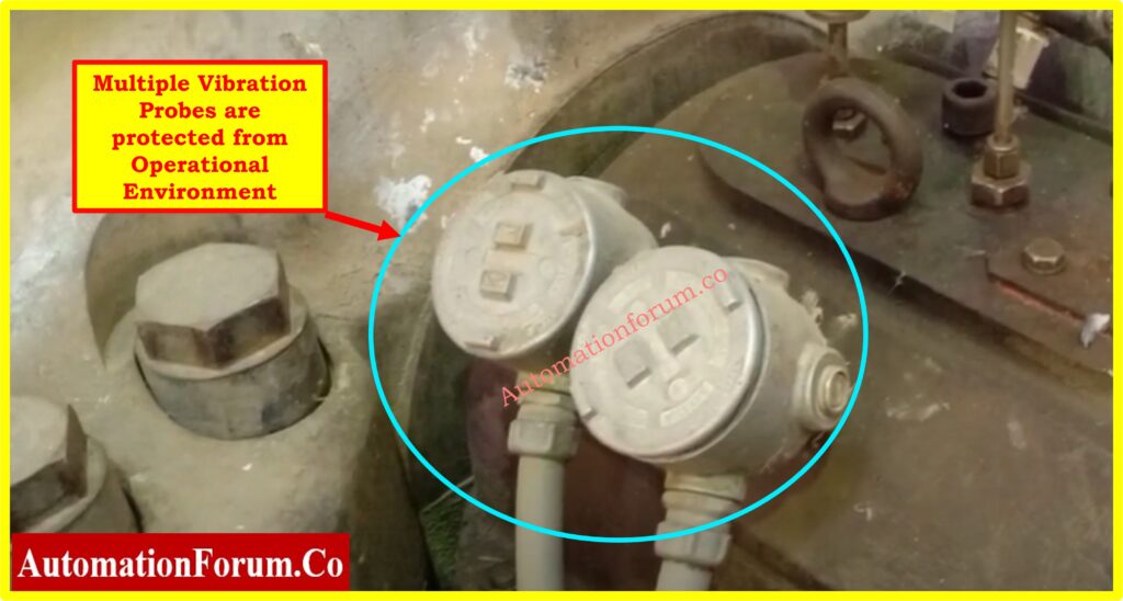
Protection Measures
- Implement protective enclosures, such as weatherproof or explosion-proof housings, if the equipment will be exposed to harsh elements or hazardous areas. These enclosures can help shield the equipment from dust, moisture, or chemical vapors that may be present in the environment.
- Use shielding or coatings on probes or cables exposed to corrosive substances, to prevent degradation over time. In areas with high electromagnetic interference (EMI), consider EMI shielding to maintain signal integrity and prevent false readings.
- Inspect any pre-existing drainage systems or ventilation around the installation area to ensure they effectively remove excess moisture or contaminants, helping maintain optimal environmental conditions for the equipment.
Step 8: Compliance with Standards
Regulatory Compliance
- Confirm that the installation aligns with relevant ISO, ANSI, and IEC standards, such as IEC 60079 for hazardous areas and ISO 10816 for vibration monitoring and analysis.
- These standards outline safety, installation, and operational guidelines to ensure equipment performance and safety.
- Document all compliance measures, including quality checks, as evidence that the installation adheres to required standards. This documentation should include inspection reports, test results, and any certification details related to the equipment.
- Verify that any modifications or installations involving electrical components comply with local electrical codes to maintain safety and prevent issues during audits or inspections.
Quality Assurance
- Perform a QA review to confirm that installation steps were followed correctly and the equipment is operational.
- Use a checklist to verify connections, component installation, and probe alignment. Document any deviations and corrective actions to ensure all issues are addressed before commissioning.
Step 9: Final Additional Checkpoints
Final Inspection
- Inspect all components, connections, and settings to ensure accuracy, stability, and compliance with specifications.
- Verify that Proximitor and BNC connectors are checked for tightness, and cables are neatly routed and secure.
Documentation Review
- Review installation logs, calibration certificates, compliance records, and all other relevant documentation to confirm completeness.
Step 10: Handover, Final Checks and Commissioning
Final Checks
- Confirm that all mechanical, electrical, and calibration procedures are complete.
- Verify that vibration probes are configured with correct parameters and alignments.
- Ensure integration with control systems, such as PLC, DCS, or SCADA, is successful. Confirm that all signals are correctly interfaced and data is accurately transmitted to the control system.
Commissioning
- Commission the system by verifying operational functionality and running final tests through the integrated control system.
- Test communication and data exchange between the vibration monitoring system and the PLC, DCS, or SCADA to ensure seamless interaction.
- Provide training to relevant personnel on system operation, including calibration, maintenance, and troubleshooting through the control system interface.
System Handover
- Prepare comprehensive documentation, including test records, Photographs of the installation, Wiring and grounding diagrams, Final gap voltage readings and settings, calibration data, and compliance reports.
- Handover the system to operations, ensuring they have a clear understanding of the equipment, control system integration, and maintenance schedules.
Downloadable Installation and Commissioning Checklist for Vibration Proximity Probe
We have prepared an Excel checklist specifically for the installation of vibration proximity probes, covering all steps from pre-installation preparations to final commissioning.

You can download it using the link below:
This above checklist provides a thorough guide, including safety protocols, mechanical and electrical installation, system integration with control systems like PLC, DCS, and SCADA, and final quality checks to ensure compliance and functionality.


