- How does the Bently Nevada vibration sensor work?
- Principle of Functional Testing of Bently Nevada Vibration Probes
- Required Tools for Functional Testing of Bently Nevada Vibration Probes:
- Safety Precautions:
- Step-by-Step Procedure for Functional Testing of Bently Nevada Vibration Probes:
- Step 1: Physical Inspection
- Step 2: Resistance and Continuity Check
- Step 3: Set Up for Probe Testing
- Step 4: Connecting the Multimeter
- Step 5: Applying Power
- Step 6: Initial Voltage Measurement
- Step 7: Incremental Distance Measurement
- Step 8: Documentation of Functional Testing:
- Step 9: Graphical Analysis of Testing
- Step 9: Evaluation of Test Results
- FAQS
- What is the voltage of Bently Nevada?
- What is the gap voltage?
- What is Turbine Supervisory Control?
- What do you mean by Turbine Supervisor System?
- What is a TSI System in a Turbine?
- What is a Condition Monitoring System or Machine Monitoring System?
The objective of this procedure is to check the characteristics and condition of Bently Nevada vibration probes, which are critical components in machinery monitoring control, turbine supervisory control, and condition monitoring systems, particularly in vibration monitoring.
How does the Bently Nevada vibration sensor work?
Principle of Functional Testing of Bently Nevada Vibration Probes
- Bently Nevada vibration probes operate based on the eddy current principle. These proximity transducers measure the distance between the probe tip and the observed surface.
- The proximitor generates a low-power radio frequency (RF) signal, which is transmitted to a coil inside the probe tip through an extension cable.
- When no conductive material is within the RF signal’s range surrounding the probe tip, nearly all the power is returned to the probe.
- However, when a conductive surface approaches the probe tip, the RF signal induces small eddy currents on the surface, leading to a measurable power loss in the RF signal. The closer the probe tip is to the target, the greater the power loss.
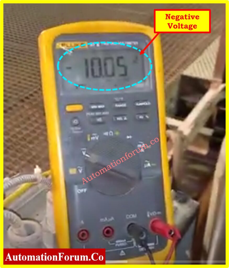
- This power loss is then used by the system to generate an output voltage(negative) that is linearly proportional to the gap between the probe tip and the target surface over a wide range.
Required Tools for Functional Testing of Bently Nevada Vibration Probes:
- Multimeter
- Micrometer (Spindle Micrometer TK-3)
- Bently Nevada Proximitor
- Extension Cable for Probe
- Power Supply
Safety Precautions:
- Check all connections before turning the system on.
- Use a power supply with the proper voltage and polarity according to the specifications for the proximitor to prevent equipment damage.
- Never operate electrical equipment without using insulated gloves and safety goggles in order to avoid electric shock.
- Always carefully hold the vibration probe and extension cable to avoid physical damage. Do not bend or physically damage the probes, as this may result in a change of reading.
- Clean the target plate of the spindle micrometer surface from dust, dirt, or any other substance that can interfere with the test results.
- Keep the workspace tidy and free from unnecessary tools or equipment that could cause accidents.
- Ensure proper lighting in the work area to avoid any mishandling or incorrect connections.
Step-by-Step Procedure for Functional Testing of Bently Nevada Vibration Probes:
Step 1: Physical Inspection
- Start by physically inspecting the vibration probe and extension cable. Look for any signs of damage, such as bends, cuts, or wear on the cable and probe.
- If any damage is detected, replace the affected parts before proceeding with the test.
How to check vibration probe Bently Nevada?
Step 2: Resistance and Continuity Check
- Use a multimeter to measure the resistance of the vibration probe. The resistance should typically be between 5 to 9 ohms, although this can vary depending on the probe model.
- Next, check the continuity of the extension cable. The resistance should be within the range of 5 to 20 ohms.
- Ensure the values are within the acceptable range for the specific model you are testing.
Step 3: Set Up for Probe Testing
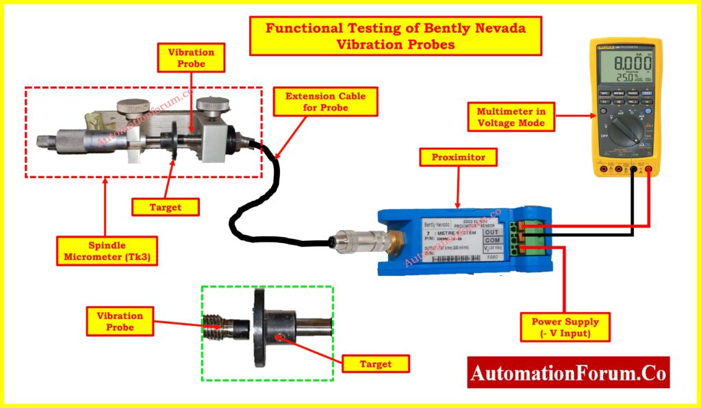
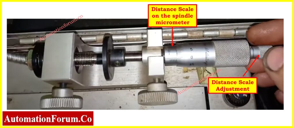
- Mount the vibration probe on the spindle micrometer (TK-3).
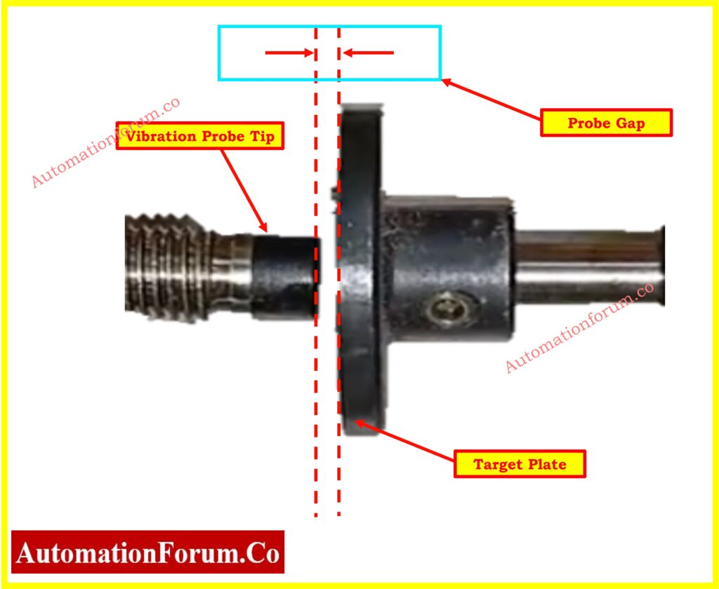
- Adjust the micrometer so that the target plate surface is aligned with the probe tip, and set the scale to zero to ensure an accurate baseline measurement.
Step 4: Connecting the Multimeter
- Connect the multimeter to the proximitor’s common (COM) and Vout (output voltage) terminals.
- Set the multimeter to measure voltage, ensuring it is configured correctly to capture the proximitor’s output.
Step 5: Applying Power
- Connect the power supply to the proximitor, ensuring the correct voltage and polarity. Double-check connections before turning on the power.
Step 6: Initial Voltage Measurement
- With the target plate set at the zero position (the closest point to the probe), record the initial output voltage(negative) displayed on the multimeter.
Click here to know more about Why we use Negative Voltage in Vibration Measurement?
Step 7: Incremental Distance Measurement
- Slowly increase the distance between the probe tip and the target plate using the spindle micrometer (TK-3).
- At each increment (e.g., every 10 mils), record the output voltage(negative) displayed on the multimeter. Continue this process until the distance reaches the maximum range (e.g., 80 or 90 mils).
Unit Conversion Table for Vibration Probes
This table provides the conversion factors commonly used in the calibration and evaluation of Bently Nevada vibration probes. Understanding these conversions is crucial for accurately interpreting the gap measurements and corresponding output voltages during functional testing.
| Measurement Unit | Equivalent Value |
| 1 mil | 0.001 inches |
| 1 mil | 0.0254 mm |
| 1 mil | 25.4 microns |
| 1 mil | 200 mVdc – response |
Click here for Vibration Unit Conversion Calculator
Step 8: Documentation of Functional Testing:
Document the all the measured output voltage(negative) at various gaps using a table like the one below:
| Gap (mils) | Output Voltage (V) |
| 0 | Initial Value |
| 10 | Record Value |
| 20 | Record Value |
| 30 | Record Value |
| 40 | Record Value |
| 50 | Record Value |
| 60 | Record Value |
| 70 | Record Value |
| 80 | Record Value |
| 90 | Record Value |
Step 9: Graphical Analysis of Testing
- Plot a graph showing the relationship between the gap (in mils) and the output voltage. The X-axis should represent the gap, while the Y-axis represents the output voltage.
Step 9: Evaluation of Test Results
- After plotting the graph, evaluate the results to determine the probe’s condition. A linear relationship between the gap and voltage within the specified range (10 mils to 80 mils) is crucial for confirming that the probe is functioning correctly.
Click here to know about GAP voltage of Bently Nevada Vibration Probe
Example Expected Linear Behavior
For instance, if you obtained the following data
| Gap (mils) | Output Voltage (V) |
| 0 | 0.0 |
| 10 | -1.5 |
| 20 | -3.0 |
| 30 | -4.5 |
| 40 | -6.0 |
| 50 | -7.5 |
| 60 | -9.0 |
| 70 | -10.5 |
| 80 | -12.0 |
| 90 | -13.0 |
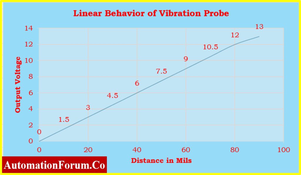
The graph should show a straight line within the range of 10 to 80 mils. This indicates that the probe is in good condition and accurately measures the gap within its operational range.
- If the graph shows non-linear behavior, such as irregular jumps or drops in voltage (e.g., the voltage flattens out or increases inconsistently), it may indicate potential issues with the probe, such as damage, calibration errors, or environmental interference.
Example of Non-Linear Data
| Gap (mils) | Output Voltage (V) |
| 0 | 0.0 |
| 10 | -1.5 |
| 20 | -2.5 |
| 30 | -4.0 |
| 40 | -5.5 |
| 50 | -7.0 |
| 60 | -8.0 |
| 70 | -8.5 |
| 80 | -8.8 |
| 90 | -9.0 |
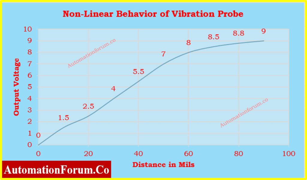
In this case, if the graph starts off linear but then flattens or curves, particularly beyond 70 mils, it suggests that the probe might be faulty or require again functional testing.
FAQS
What is the voltage of Bently Nevada?
Bently Nevada systems, particularly the proximity probes like the 3300 and 3500 series, typically operate with a DC power supply voltage in the range of -18V to -24V. This voltage is used to power the sensor and drive the electronics for processing the vibration signals.
What is the gap voltage?
The gap voltage refers to the DC voltage measured across the proximity probe and its target surface when the probe is installed and the machine is at rest. For Bently Nevada proximity probes, the gap voltage is typically in the range of -8V to -12V. This voltage represents the distance between the probe tip and the target surface; as the gap increases, the voltage becomes less negative, and as the gap decreases, the voltage becomes more negative.
What is the principle of Bently Nevada 3500?
- The Bently Nevada 3500 system operates based on the principle of eddy current displacement sensing.
- The proximity probe, a key component, generates an electromagnetic field that induces eddy currents on the conductive surface of the rotating machine part (e.g., a shaft).
- The probe measures the changes in the gap between the probe tip and the target surface, which corresponds to the displacement of the machine part.
- These measurements are used to monitor and analyze vibration, shaft position, and other critical parameters, helping in predictive maintenance and protecting rotating machinery.
What is Turbine Supervisory Control?
Turbine Supervisory Control refers to the monitoring and control systems designed to ensure the safe, efficient, and reliable operation of turbines, typically in power generation. These systems continuously monitor critical parameters such as vibration, speed, temperature, and pressure, providing real-time data to operators. They automatically adjust operating conditions to maintain the turbine within safe limits, initiate protective actions if abnormal conditions are detected, and ensure the turbine operates at optimal efficiency.
What do you mean by Turbine Supervisor System?
A Turbine Supervisor System is essentially a control and monitoring system specifically designed to supervise and manage the operation of a turbine. It oversees various parameters like rotor speed, bearing vibrations, axial displacement, and differential expansion. The system can also provide alerts, alarms, and control actions to protect the turbine from damage due to abnormal operating conditions. It is a critical part of the turbine’s overall control architecture, ensuring safe and stable operation.
What is a TSI System in a Turbine?
TSI (Turbine Supervisory Instrumentation) is a system used in turbines to monitor and measure key operational parameters, such as vibration, axial position, differential expansion, and rotor speed. The TSI system provides critical data to operators and automated systems, enabling them to maintain the turbine’s safe and efficient operation. It plays a vital role in the early detection of potential issues, allowing for timely intervention and preventing catastrophic failures.
What is a Condition Monitoring System or Machine Monitoring System?
A Condition Monitoring System (also known as a Machine Monitoring System) is used to continuously monitor the health and performance of machinery, including turbines, compressors, pumps, and other rotating equipment. This system collects and analyzes data on various parameters like vibration, temperature, pressure, and oil condition. The purpose is to detect any deviations from normal operating conditions that could indicate developing faults or inefficiencies. Condition monitoring allows for predictive maintenance, reducing unplanned downtime, and extending the life of the machinery by addressing issues before they lead to significant failures
What is the principle of a vibration sensor?
The principle of a vibration sensor (also known as a vibration transducer) depends on its type and choice of sensor depends on the specific application and the frequency range of interest.
Piezoelectric Sensors
These sensors use piezoelectric materials that generate an electric charge when subjected to mechanical stress, such as vibrations. The charge is proportional to the acceleration of the vibrating surface, and it is converted into a voltage signal that can be measured and analyzed.
Electromagnetic Sensors
These sensors consist of a coil and a magnet. As the vibrating surface moves, it causes relative motion between the coil and the magnet, inducing a voltage in the coil proportional to the velocity of the vibration.
Capacitive Sensors
These sensors measure changes in capacitance caused by the vibration-induced displacement between two plates. The varying capacitance is converted into an electrical signal representing the vibration.


