- Test 1: Calibration of RTD
- Test 2: Insulation Resistance Test at Ambient Temperature
- Test 3: Insulation Resistance Test at 320°C
- Test 4: N2 Leakage Test
- Test 5: Response Time Test
- Test 6: Special Test – Autoclave Test
- Test 7: Continuity Test
- Test 8: Sheath Integrity Test – Water Immersion Test
- Test 9: Response Time Test with RTD Connected to a Pipe
- Test 10: Self-Heating Error Test
- Resistance Versus Temperature Table for DIN-IEC-751 Platinum RTDs
- What is self-heating error in RTD?
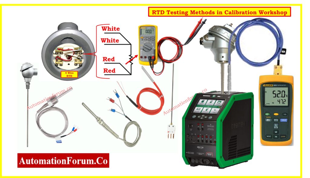
- How do you test an RTD?
- What are the methods of measuring RTD?
- What is the formula for PT100?
Detailed procedures for RTD calibration and testing methods ensure accurate temperature measurements and reliable performance in various applications.

Test 1: Calibration of RTD
Purpose:
To ensure the RTD provide an accurate temperature measurements.
Reference Standards:
IEC 751 / DIN 43760 Class A & B.
Two-Point Calibration:
This is the most often used calibrating technique.
- Using an ice bath the 0°C point calibration is accomplished. To prevent the RTD sensor tip from touching the container sides which could compromise accuracy it should be immersed in a solution of crushed ice and distilled water.
- Boiling water is used to achieve the 100°C point calibration. It is important that the RTD sensor tip be completely submerged in the boiling water and shielded from any steam pockets. Here precise calibration is ensured by constant boiling.
Three-Point Calibration (or more):
- More calibration points are needed for greater accuracy over a wider temperature range.
- In order to provide more data points for calibration temperature baths or dry-block calibrators are set at particular intermediate temperatures like 50°C or 200°C.
- To avoid outside impacts on temperature readings, calibration should take place in a controlled environment.
- Routine calibration checks are advised to help to maintain accuracy over time.
Equipment Needed:
- Precision temperature bath or dry block calibrator.
- High-accuracy reference digital thermometer.
Refer the below link for the 8 Steps RTD Calibration Procedure
Test 2: Insulation Resistance Test at Ambient Temperature
Purpose:
To ensure the electrical insulation of the RTD is intact, preventing electrical leakage and potential short circuits.
Testing Procedure:
- To isolate the RTD for testing unplug it from any circuitry.
- Attach the insulation resistance tester leads to the sheath and RTD element. Measure the insulation resistance and apply 500 VDC.
- Apply 500 VDC and measure the insulation resistance.
- Greater than 100 M ohms, the resistance indicates good insulation and low electrical leakage.
- Insulation resistance tests should be carried out on a regular basis to ensure the RTD’s long-term reliability.
- Stable ambient temperature conditions help to keep resistance measurements consistent.
Equipment Needed:
- Insulation resistance tester (megger)
Test 3: Insulation Resistance Test at 320°C
Purpose:
To ensure the RTD maintains insulation integrity at elevated temperatures, preventing degradation and ensuring long-term reliability.
Testing Procedure:
- Heat the RTD to 320°C in a controlled oven or furnace to ensure consistent temperature dispersion.
- Allow the RTD to settle at this temperature before testing.
- Apply 100 VDC with an insulating resistance tester.
- The resistance should be larger than 2 M ohms, preferably more than 20 M ohms, for increased reliability.
- RTDs used in variable temperature situations require high-temperature testing.
- Repeated tests can aid in detecting any potential decline over time.
Equipment Needed:
- Oven or furnace
- Insulation resistance tester
Test 4: N2 Leakage Test
Purpose:
To ensure the integrity of the welds and seals in the RTD sensor, preventing gas or liquid ingress that could affect performance.
Testing Procedure:
- After cap welding, connect the RTD sensor to a nitrogen gas source.
- Apply pressure at 40 kg/cm².
- Use a leak detector or soapy water to check for bubbles indicating leaks.
- No leakage should be observed, ensuring the sensor is properly sealed.
- The N2 leakage test is essential for RTDs used in high-pressure or hazardous environments.
- Proper handling and sealing techniques are critical to passing this test.
Equipment Needed:
- Nitrogen gas supply
- Standard reference Pressure gauge
- Leak detector (e.g., soapy water, electronic leak detector)
Test 5: Response Time Test
Purpose:
To determine how quickly the RTD responds to changes in temperature, which is critical for dynamic temperature measurements.
Reference Standard:
IEC 751 – 63.2% step change from ambient to 80°C.
Testing Procedure:
- For RTDs without a transmitter, immerse the RTD in a controlled temperature bath that can rapidly change temperature.
- Measure the time taken for the RTD to reach 63.2% of the step change.
- Typical response time is 6 to 9 seconds for sheaths up to 6 mm OD.
- For RTDs with thermowells, the response time is longer due to the additional thermal mass.
- Typical response time is 35 to 45 seconds.
- The response time test ensures the RTD can accurately track rapid temperature changes in its environment.
- Calibration and verification should be performed periodically to maintain accuracy.
Equipment Needed:
- Temperature bath
- Stopwatch or data logger
Test 6: Special Test – Autoclave Test
Purpose:
To test the RTD’s performance under high-pressure steam conditions, simulating sterilization environments.
Testing Procedure:
- Place the RTD in an autoclave set to 125°C and 1.2 kg/cm² steam pressure.
- Maintain these conditions for about 1 hour.
- After the test, measure the insulation resistance.
- The insulation resistance should be more than 5 M ohms, indicating the RTD can withstand sterilization conditions without degradation.
- This test is crucial for RTDs used in medical or food processing industries where sterilization is routine.
- Regular testing ensures the RTD’s longevity and reliability in such environments.
Equipment Needed:
- Autoclave
- Insulation resistance tester
Test 7: Continuity Test
Purpose:
To confirm the electrical continuity of the RTD element and its connection to the transducer cable, ensuring proper operation.
Testing Procedure:
- Use a continuity tester or multimeter.
- Connect the tester leads to the RTD leads.
- Check for continuity.
- A continuous circuit indicates proper connection. No continuity would indicate a broken element or connection.
- The continuity test is a basic but essential check to ensure the RTD is properly wired and operational.
- This test should be conducted regularly, especially after installation or maintenance.
Equipment Needed:
- Continuity tester or multimeter
Test 8: Sheath Integrity Test – Water Immersion Test
Purpose:
To ensure the sheath of the RTD or thermocouple cable is intact and free of leaks, preventing moisture ingress that could affect performance.
Testing Procedure:
- Immerse the RTD in water. Keep an eye out for any bubbles or leaks.
- A good sheath integrity is indicated by the absence of bubbles and moisture ingress.
- For RTDs used in moist or humid environments the water immersion test is essential.
- The sensors long-term dependability is enhanced by routine testing.
Equipment Needed:
- Water bath
- Leak detector
Test 9: Response Time Test with RTD Connected to a Pipe
Purpose:
To evaluate the response time of an RTD when installed on a pipe carrying fluid, simulating practical application conditions.
Testing Procedure:
- A pipe with 20 liters of water flowing per second at 80°C should have the RTD attached to its exterior surface.
- Time how long it takes the RTD to react to a temperature change.
- In order to guarantee that the RTD can precisely monitor temperature changes in the pipe response times should be less than 20 seconds.
- For RTDs which are frequently installed on pipes in process industries this test is essential.
- Maintaining precise process control is aided by guaranteeing a rapid response time.
Equipment Needed:
- Pipe setup with controlled water flow and temperature
- Stopwatch or data logger
Test 10: Self-Heating Error Test
Purpose:
To assess the effect of self-heating on RTD accuracy, which can introduce errors in temperature measurement.
Reference Standard:
IEC 751.
Testing Procedure:
- After applying a known current to the RTD take a temperature reading.
- To find the self-heating error compare this temperature to the one without current.
- Minimal impact on measurement accuracy is ensured by ensuring that the self-heating error falls within the acceptable limits as specified by IEC 751.
- To ensure the accuracy of the RTD self-heating error tests are essential particularly in applications where accurate measurements are crucial.
- Frequent testing assists in detecting and reducing any potential long-term self-heating effects.
Equipment Needed:
- Precision current source
- Resistance measurement equipment
Resistance Versus Temperature Table for DIN-IEC-751 Platinum RTDs
Refer the below link to download the Resistance Versus Temperature Table for DIN-IEC-751 Platinum RTDs
Frequently Asked Questions
What is self-heating error in RTD?
- Self-heating error in an RTD (Resistance Temperature Detector) occurs because the current running through the RTD causes it to dissipate power as heat.
- This internal heating can increase the temperature of the RTD itself, leading to an error in the temperature measurement.
- When an electric current flows through the RTD, it generates heat due to the electrical resistance of the RTD material.
- This heat raises the temperature of the RTD above the actual ambient or process temperature, causing the RTD to measure a higher temperature than the true temperature.
- The amount of self-heating depends on the power dissipation and the RTD’s self-heating coefficient.
- The self-heating coefficient varies depending on the RTD’s design, construction, and environment. It is typically provided by the RTD manufacturer and is expressed in mW/°C.
- The temperature change (?T) is calculated by dividing the power dissipation of the RTD by the self-heating coefficient E, measured in mW/°C.
Click here for RTD Temperature Coefficient Calculation
How do you test an RTD?
Testing an RTD is straightforward. Here’s how you can do it:
- First, inspect the RTD for any physical damage. Look for any signs of wear, corrosion, or breaks in the sensor or wiring.
- Use a digital multimeter to measure the resistance of the RTD at room temperature. For a PT100 RTD, the resistance should be close to 100 ohms at 0°C. Any significant deviation might indicate a problem.
- Place the RTD in an ice bath (0°C) and check the resistance. It should read approximately 100 ohms for a PT100. This confirms the RTD’s accuracy at a known temperature.
- Place the RTD in boiling water (100°C) and measure the resistance. For a PT100, it should read around 138.5 ohms.
- Use a calibrated temperature source or dry block calibrator to check the RTD’s response across a range of temperatures. Compare the readings against a standard RTD curve or calibration chart.
Click here for RTD Tolerance Calculation
What are the methods of measuring RTD?
Measuring RTD can be done using several methods:

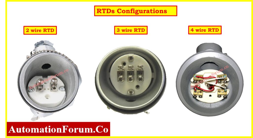
Two-Wire Configuration:
This is the simplest method where two wires are connected to the RTD. However, it includes the resistance of the lead wires, which can affect accuracy.
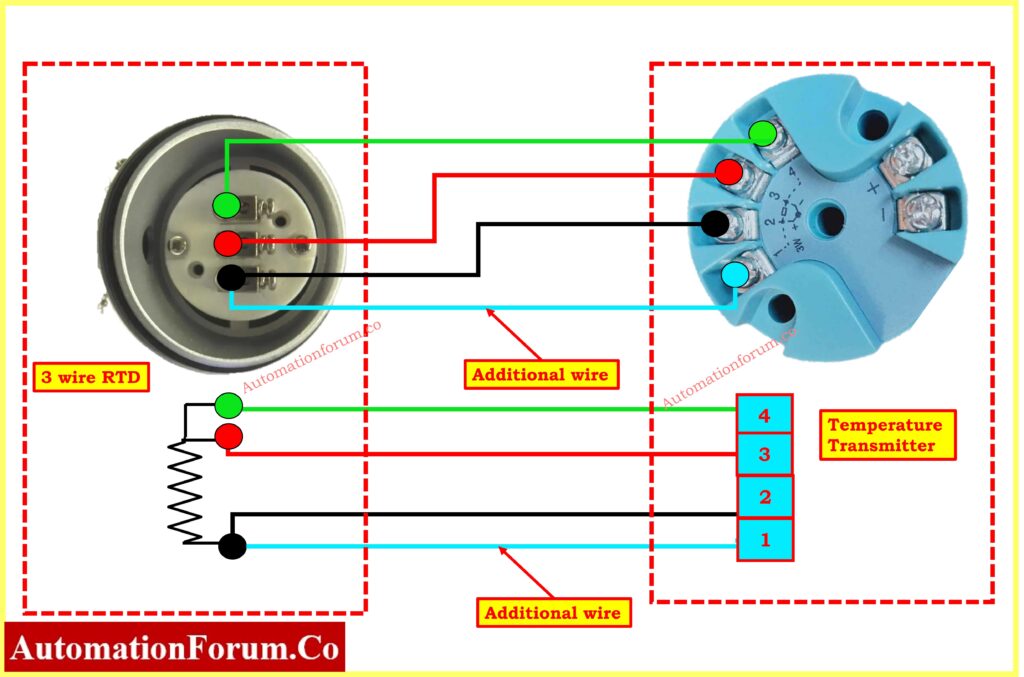
Three-Wire Configuration:
This method compensates for the lead wire resistance by using a third wire. It’s commonly used in industrial applications because it improves accuracy without adding complexity.
Click here for Converting 2-Wire and 3-Wire RTDs into 4-Wire RTDs
Four-Wire Configuration:

The most accurate method, it uses four wires to completely eliminate the effect of lead wire resistance. This is typically used in laboratory settings where high precision is required.
Click here for Why 4 wire RTD’s measurement accuracy is better than 2 and 3 wire RTD?
What is the principle of RTD?
RTDs operate on a simple principle: the resistance of a metal increases with temperature. RTDs are made from pure metals, most commonly platinum, and they provide a very accurate and stable measurement of temperature. The resistance change is predictable and repeatable, making RTDs reliable for precise temperature measurement.
What is the formula for PT100?
For a PT100 RTD, the resistance-temperature relationship can be approximated by the following formula:
R(T)=R0×(1+?×T)
- R(T) is the resistance at temperature T.
- R0 is the resistance at 0°C (which is 100 ohms for PT100).
- ? is the temperature coefficient of resistance, approximately 0.00385 ohms/ohm/°C for platinum.
- T is the temperature in degrees Celsius.
Click here for RTD Calculator: Converting Measured Resistance to Process Temperature
Click here for RTD Calculator: Converting Process Temperature to measured Output Resistance


