What is a temperature transmitter RTD?
The electrical resistance of the RTD sensor varies as the temperature changes. They are suited for measuring temperatures ranging from -200 °C to about 600 °C and distinguish themselves via exceptional measurement accuracy and long-term stability. A Pt100 sensor element is the most often used sensor element.
How do you calibrate a temperature transmitter?
Purpose and Scope:
This procedure describes in detail how to calibrate RTD (resistance temperature detector) temperature transmitters in the process area using standards.
Tools required for DP transmitter calibration:
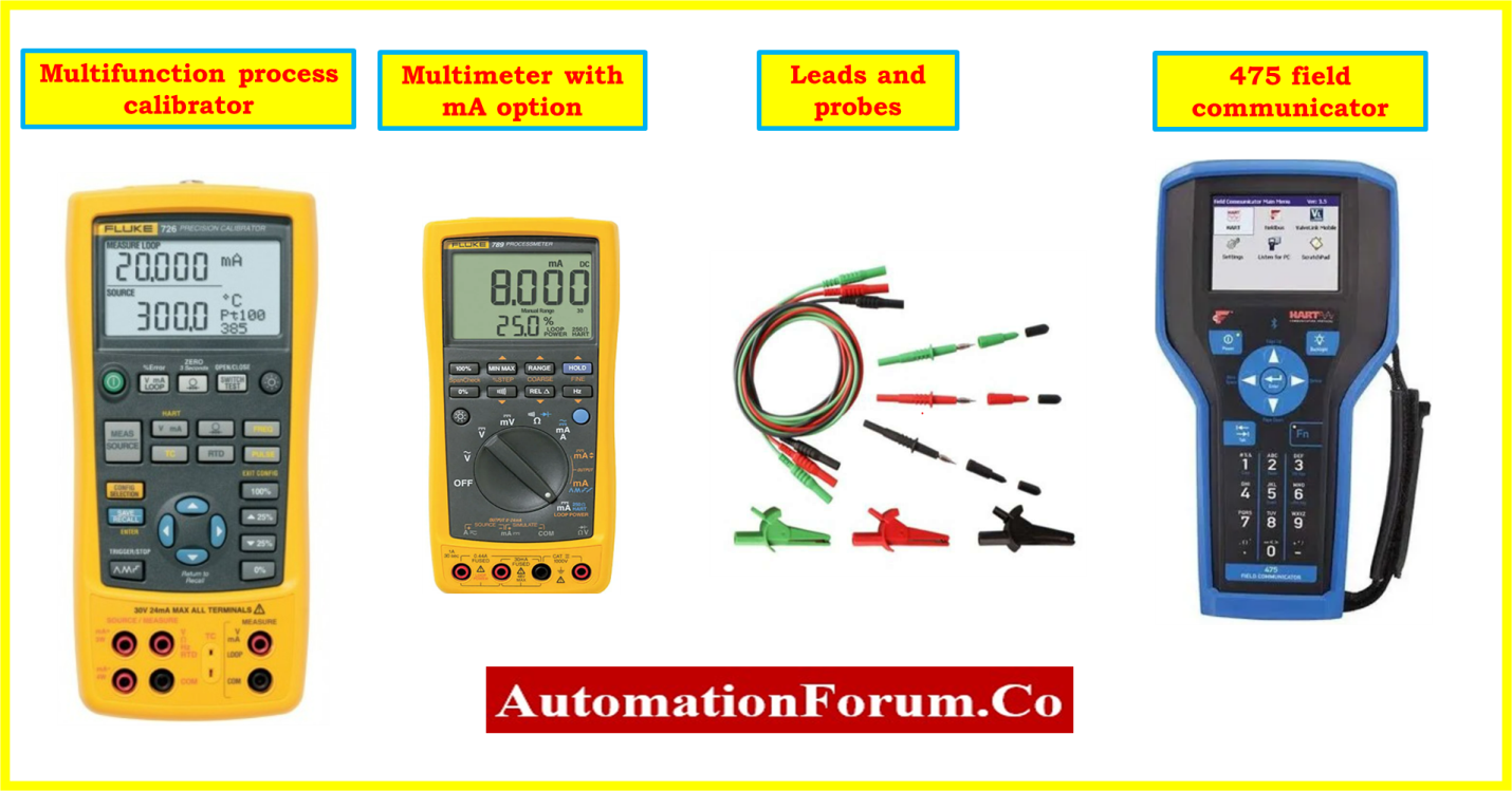
- Necessary hand tools.
- Multifunction process calibrator.
- Standard Multimeter.
- Test leads and probes..
- Soft Cloth for cleaning.
- Communicating instruments are necessary, such as a 475 Hart communicator if it is a smart RTD temperature transmitter.
Safety
- Please click on this page for additional details on process industry fundamental safety and general calibration process recommendations.
Process Industry Calibration Procedure: Fundamental Safety and General Considerations
- Ask the panel operator to set the MOS (Maintenance Override Switch) for the RTD temperature transmitter control loop and the ESD loop in manual mode on the controller.
- The RTD temperature transmitter that needs calibration should be located.
- Check to make sure the RTD temperature transmitter is the right one, and make a note of any crucial information, such as the Tag number (e.g. the manufacturer, model number, temperature range, type of sensor & etc.).
- Remember that depending on the individual RTD temperature transmitter and the process location, this basic procedure may need to be changed. While dealing with an RTD temperature transmitter or any other part of process equipment, always adhere to the manufacturer’s instructions as well as local safety regulations.
- To avoid an unintentional start, adhere to all applicable lockout/tagout requirements. Ensure that the RTD temperature transmitter is isolated from the process
Calibration Setup

- The position of the RTD temperature transmitter and calibration tools must be free from electromagnetic noise and vibrations. Also, the space must be adequately illuminated and ventilated.
- Get all the tools and supplies required for the RTD temperature transmitter calibration.
- By using the instrument loop diagram as a guide, power should be switched off for the RTD temperature transmitter and any wires or connectors should be removed from the nearby junction box or Marshalling panel.
- Determine the RTD cable that is attached to the temperature transmitter. This cable, which is often core marked, may be connected to a separate terminal block or connector on the RTD temperature transmitter.
- Once the RTD cable has been taken out, look for any evidence of wear or damage. Before re-attaching it to the temperature transmitter, it should be checked for damage and replaced if necessary.
- The removed cable has to be labeled, insulated, and secured for connecting abc after the calibration.

- The probe cable is attached to the transmitter’s RTD input terminal on one end, and the process calibrator’s RTD signal simulation terminal on the other, as shown in the image. For instance, if the RTD has four wires, a four-wire probe must be used to connect to both sides.
- Using probes and a lead, establish a series connection to the multimeter’s analogue input loop between the junction box and the RTD temperature transmitter.
- Set up communication by connecting the HART communicator to the RTD temperature transmitter’s terminal, if it is a smart type transmitter.
- As shown in the diagram, the connections have been made and are presently being ready for the calibration of the RTD temperature transmitter.
Calibration procedure
- Check the RTD temperature transmitter’s power wire connections and simulation input connections from the calibrator for stability.
- Switch on the power supply for the RTD temperature transmitter and make sure it is present in the transmitter’s terminal.
- You can validate a number of RTD temperature transmitter parameters by looking at the instrument data sheet. The tag number, type, LRV, and URV are typical parameters.
- Find out what type of RTD, such as a PT100, PT500, or other type, is connected to the temperature transmitter with the help of datasheet or HART communicator for smart transmitter. Moreover, find out the RTD coefficient factor for use in setting up the process calibrator to simulate the signal.
- Switch on the process calibrator, must choose RTD source mode, and the RTD input type on the calibrator using the data sheet with the relevant coefficient factor.
- Set the transmitter’s LRV and URV to configure the simulation input range in the process calibrator.
- In this calibration, the RTD is replaced out for a multifunction process calibrator that generates a temperature range in ohms with the appropriate type of RTD.
- For the Zero and Span settings on older RTD temperature transmitters, multi-turn potentiometer adjustments were available.
- When the simulated RTD input temperature is 0%, the Zero pot is set to create 4 mA, and when the simulated RTD output temperature is 100%, the Span pot is set to produce 20 mA.
Example calibration
- Assuming a temperature range of -10 to 110 degrees Celsius, let’s calibrate a temperature transmitter coupled to a PT100 RTD with 0.00391 coefficient factor as an example.
- Now configure the calibrator’s calibration parameter to the RTD type PT100, 0.00391 coefficient factor, 50-degree LRV, and 100-degree URV.
- Now set the calibrator to inject a -10 °C (LRV) temperature signal, and check the multimeter; it should show 4 mA.
- If the 4mA measurement is not displayed on the multimeter display, adjust the RTD thermocouple temperature transmitter output using the Zero adjustment.
- For Span calibration, set the calibrator to inject a temperature signal at 110 °C (URV). After that, check the multimeter; it should read 20 mA.
- Adjust the RTD temperature transmitter output using the span adjustment if the multimeter display does not show the 20mA measurement.
- If the RTD temperature transmitter is SMART-compatible, you may use the HART communicator to change the zero/Span current value.
- Repeat the calibration method as often as necessary to calibrate the RTD temperature transmitter to the desired tolerance.
- Depending on the specific process calibrator and RTD temperature transmitter being used, the calibration method may change.
- Hence, before beginning, be sure to follow the transmitter manual and the process calibrator manufacturer’s manual.
Recording calibration
- To make sure the RTD temperature transmitter is generating the right output values, check the linearity of the temperature transmitter output at 0%, 25%, 50%, 75%, and 100% in both the upscale and downscale directions.
- Use this formula to convert the needed output reading (mA) into the necessary units (temperature).
For Desired current output signal (mA):
I mA=[(maxi. mA-min. mA )/(URV temp.-LRV temp.)]*(PV measured temp.-LRVtemp)+min. mA
For Desired temperature process value :
PV temp.=[((URV temp.-LRV temp.)/(maxi. mA-min. mA)]*(I measured mA-min. mA))+LRV temp.
- If the output value does not fall within an acceptable range, the RTD temperature transmitter has to be calibrated. The RTD temperature transmitter has to be serviced or replaced if the output values have once again drifted outside of the allowed range.
- If all output values (+/- %) are within tolerable limits, further calibration of the RTD temperature transmitter is not required.
- The output data reading from the RTD temperature transmitter should be entered in the as found/as left column of the blank calibration report.
Completion of calibration
- Once the calibration has been completed successfully, apply the calibration label to the RTD temperature transmitter.
- When the calibration is finished, clean the test tools and communicator, store them securely, and save the RTD temperature transmitter calibration data for later use.
- Disconnect the multifunction process calibrators, RTD temperature transmitter connections, and other calibration equipment.
- In the processing area, connections must be established for the RTD temperature transmitter.
- Go over the calibration site to make sure it’s clean.
- De-isolate the apparatus.
- Restore the bypassed or inhibited level of the RTD temperature transmitter signal.
- Check the RTD temperature transmitter’s functionality before utilizing it.
Sample calibration report
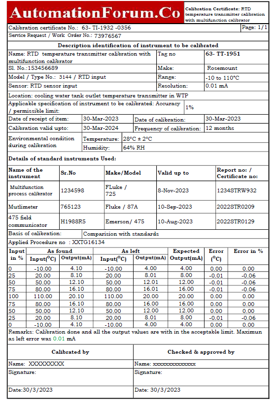
An example of how a multimeter and process calibrator were utilized as a reference to calibrate an RTD temperature transmitter sample report in a process region is shown in the accompanying picture.
You may obtain the Excel document that was used to construct the RTD temperature transmitter calibration report by clicking on the link below.