
- Why Is My Solenoid Valve Energized but Not Actuating?
- Understanding How a Hydraulic Solenoid Valve Works
- Common Symptoms of a Solenoid Valve Energized but Not Actuating
- Root Causes of Solenoid Valve Energized but Valve Not Actuating
- Step by Step Troubleshooting Procedure for Hydraulic Solenoid Valves
- Instrumentation Tests Every Engineer Should Perform
- Hydraulic Problems That Mimic Electrical Faults
- PLC and Control Circuit Troubleshooting for Hydraulic Solenoid Valves
- Real Industrial Case Study: Solenoid Valve Energized but Not Actuating
- Common Mistakes Engineers Should Avoid During Solenoid Valve Troubleshooting
- Frequently Asked Questions About Solenoid Valve Energized but Valve Not Actuating
- Practical Takeaways for Instrumentation and Maintenance Engineers
Why Is My Solenoid Valve Energized but Not Actuating?
Solenoid Valve Energized But Valve Not Actuating is a common defect in industrial hydraulic systems that can lead to unexpected machine downtime and complicated troubleshooting. Although the PLC output is ON, the indicator lamp is lit and the solenoid coil is getting the right voltage, the hydraulic valve may not shift and the actuator may not move.
The problem is frequently caused by factors other than the solenoid itself; for example, malfunctioning control circuits, low pilot pressure, polluted hydraulic oil, sticky valve spools or PLC interlocks. Replacing the valve is just a stop gap measure.
A methodical approach to troubleshooting through PLC diagnostics, electrical testing, instrumentation checks and hydraulic verification allows engineers to swiftly pinpoint the main problem. This guide provides practical troubleshooting methods and established field practices that enhance equipment reliability and save maintenance downtime.
Understanding How a Hydraulic Solenoid Valve Works
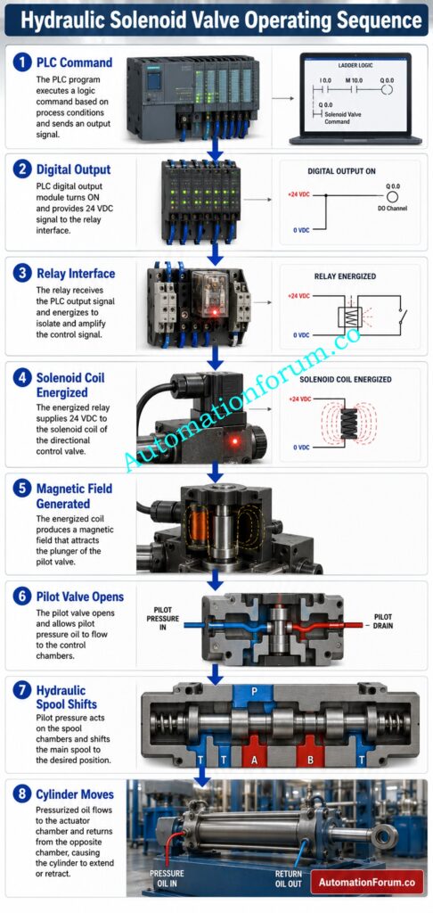
Before initiating any troubleshooting action, it is important to understand the entire functioning sequence. Supplying electrical current to the solenoid coil does not mean the hydraulic directional control valve is activated. It is, instead, dependent upon an orchestrated sequence of electrical, magnetic and hydraulic processes.
Electrical Control Circuit Operation
Can You Solve These PLC Output Failures Like Experts?: Troubleshooting PLC Digital Output Signals – Advanced Industrial Quiz for Automation Engineers
PLC Output and Relay Logic

In many industrial applications the PLC output is not directly energizing the coil. Instead, it energizes an intermediary or interposing relay which switches the 24 VDC or 110 VAC supply to the valve coil. This configuration shields the PLC output card and makes maintenance easier.
Resolve Field And Control Room Reading Conflicts With Confidence: Loop Checking Field vs Control Room Reading Mismatch Explained
Solenoid Coil and Magnetic Field Generation
When the proper voltage is applied to the coil, electric current will flow through the winding and produce a magnetic field. This magnetic force attracts the armature or plunger in the solenoid assembly.
The motion of the armature provides the mechanical force required to move the valve spool or to operate a pilot mechanism. If the magnetic force is not sufficient because of low voltage, coil damage or too much resistance, the coil may seem to be energized, but the spool may not move from its initial position.
Hydraulic Directional Valve Operation
In direct operated valves the solenoid directly shifts the spool.
In pilot operated valves, the energized solenoid opens a small pilot passage initially. The larger directional control valve is moved by the force of the pilot hydraulic pressure on the spool.
As the spool moves, hydraulic oil follows different flow routes within the valve body, sending pressure to the proper side of the actuator and returning oil from the other side to the hydraulic tank.
If the pilot pressure is absent or the internal channels are plugged, the spool won’t move, even if the electrical circuit is good.
Relationship Between Electrical Control and Hydraulic Systems
The crucial thing to know is that electrical energization is merely the first phase. Free spool movement, all controlled by accurate control logic, depends on healthy electrical components, proper hydraulic pressure, clean oil and successful valve functioning.
Refer the below link for theWhat is a Spool Valve? Configuration, Construction & application
Common Symptoms of a Solenoid Valve Energized but Not Actuating
Field symptoms help to narrow the troubleshooting process and prevent unnecessary replacement of costly hydraulic components.
Maintenance engineers typically report observations such as:
- PLC digital output is ON.
- Solenoid indicator light is on.
- Coil voltage rating of connection.
- Energization of solenoid coil causes heating.
- You hear an audible hum or click from the valve.
- Hydraulic directional valve spool is stuck.
- Hydraulic cylinder or actuator will not travel.
- Manual override successfully opens the valve.
- Hydraulic system pressure is normal.
- Pilot pressure gauge reads low or zero pressure.
- Control fuse is OK and does not blow.
- PLC, DCS: No electrical alerts are seen.
- Valve acts on repeated commands intermittently.
- Actuator reaction to load is slow.
- The valve body is tapped, and the machine continues functioning for a while.
- The PLC Output LED is active and the hydraulic function is not active.
These are indicators that the valve is not working successfully despite electrical power being there. Before determining the true root cause, the engineers also need to check the control circuit and the hydraulic system.
Refer the below link for the Step-by-Step Procedure for Troubleshooting PLC Digital Outputs
Root Causes of Solenoid Valve Energized but Valve Not Actuating
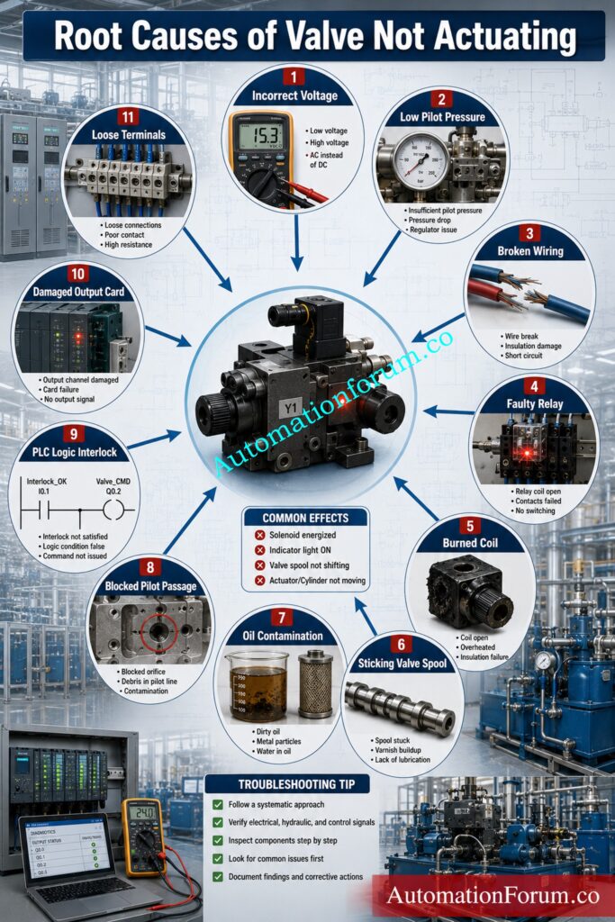
Below is a table summarizing the most typical causes for an energized solenoid valve but valve not activating condition for industrial hydraulic systems.
| Possible Cause | Typical Symptoms | How to Verify | Recommended Action |
| Incorrect supply voltage | Weak magnetic pull, slow operation | Measure voltage at the coil under load | Restore the correct supply voltage |
| Low voltage due to voltage drop | Coil energizes but spool does not shift | Perform voltage drop testing across cables and terminals | Repair loose or damaged wiring |
| Loose terminal connection | Intermittent operation | Tighten and inspect all terminal blocks | Secure connections and replace damaged terminals |
| Broken wire or cable | No current flow despite PLC output ON | Check continuity with a digital multimeter | Repair or replace the cable |
| Faulty relay contacts | Relay energizes but output voltage fluctuates | Measure voltage across relay contacts | Replace worn relay contacts |
| Damaged PLC output card | Output LED ON but no stable voltage | Verify output using PLC diagnostics and multimeter | Replace or repair the PLC output module |
| Open neutral or return path | Voltage appears unstable | Measure return circuit continuity | Restore the neutral or return connection |
| Failed solenoid coil | Coil overheats or shows infinite resistance | Measure coil resistance | Replace the solenoid coil |
| Burned connector or DIN plug | Discoloration or loose electrical connection | Inspect connector visually | Replace the connector assembly |
| Mechanical spool sticking | Manual override difficult to operate | Remove and inspect the spool | Clean or replace damaged components |
| Hydraulic oil contamination | Intermittent valve movement | Inspect oil sample and filters | Replace oil and filters |
| Loss of pilot pressure | Coil energizes but spool remains stationary | Measure pilot pressure using a pressure gauge | Restore pilot pressure |
| Blocked pilot passage | No spool movement despite correct pressure | Inspect pilot ports during maintenance | Clean internal passages |
| Incorrect replacement coil | Coil heats but magnetic force is weak | Verify voltage, power rating, and part number | Install the correct replacement coil |
| Incorrect wiring or safety interlock | Valve never receives complete operating command | Compare wiring with electrical drawings and PLC logic | Correct wiring and verify control logic |
Fix Stubborn Valve Failures Before They Stop Production Completely: Step-by-Step Procedure to Troubleshooting Solenoid Valves in PLC Digital Output Loops
Step by Step Troubleshooting Procedure for Hydraulic Solenoid Valves
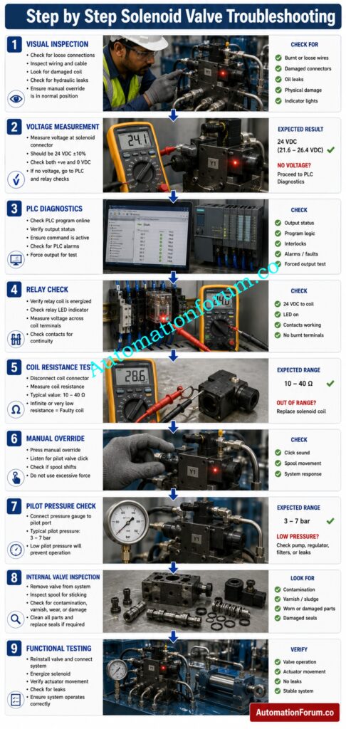
The systematic troubleshooting procedure enables experts to locate the actual defect without replacing good components. Always do the simplest checks before bothering to dismantle the hydraulic valve. Document each measurement and compare it with equipment manufacturer requirements.
Step 1: Perform a Visual Inspection
Visually check the hydraulic valve assembly and control panel completely.
Check for:
- Loose electrical connections
- Broken wires.
- DIN connectors burned
- Oil leaking around the valve body
- Conduit fittings damaged
- Terminals with loose screws
- Cable glands damaged
- Overheating Symptoms
- Corrosion of electrical terminals
Many intermittent failures are caused by faulty electrical connections rather than failing hydraulic components.
Step 2: Verify Control Voltage
Measure voltage directly across the solenoid coil terminals with the PLC command active.
Never measure voltage with the connector unplugged. An open circuit may show a good voltage even if there is excessive resistance in the wiring.
Industrial control voltages are typically:
- 24 VDC
- 48 VDC
- 110 VAC
- 230 VAC
A good 24 VDC coil will generally read between 23 and 25 VDC under load. If the reading is high, the problem is probably excessive voltage drop, bad wiring, bad terminals, or worn relay contacts.
Step 3: Verify PLC Output
Open the PLC online diagnostics and verify the output is truly being commanded.
Confirm:
- Output address status
- Output LED
- Module diagnostics
- Output fault messages
- Interlock conditions
- Emergency stop status
- Permissive signals
An lighted output LED doesn’t necessarily mean enough output current.
Everything Engineers Must Know About Directional Control Valves Today: What is Directional Control Valve (DCV)?
Step 4: Inspect the Relay Interface
Many hydraulic valves are operated using an interposing relay.
Verify:
- Coil voltage of relay
- Contact resistance of relay
- Contact heating.
- Relay socket status
- Loose Wires
Voltage may be showing up on a voltmeter due to burned relay contacts, but not enough current to reach the solenoid.
Prevent Power Supply Overloads Using This Smart Engineering Calculator: Instrument Power Supply Load Calculator: 7 Critical Steps for Accurate 24VDC Power Supply Sizing
Step 5: Measure Coil Resistance
Measure resistance with the power off.
Compare the measured value with the manufacturer’s specs.
Typical observations are:
- The coil is open, infinite resistance.
- A very low resistance suggests an interior short circuit.
- Large fluctuations in resistance on heating of the coil will indicate the degeneration of the winding.
If the measurements are outside the specified range, change the coil.
Eliminate Remote IO Communication Failures Faster Than Ever Before: PLC Troubleshooting Remote IO Rack Communication Failure Complete Troubleshooting Guide for Industrial Automation Engineers
Step 6: Perform Insulation Resistance Testing
Check coil insulation with an insulation resistance tester where plant processes permit.
Low insulating resistance may be a sign of:
- Water penetration
- Coil getting too hot
- Insulation Failure
- Internal contamination
This test is especially useful for outdoor installations and high humidity situations.
Step 7: Inspect Connectors and Terminal Blocks
Remove the DIN connector and inspect for:
- Burn marks
- Loose pins
- Corrosion
- Moisture
- Cracked insulation
Also, tighten all the terminal screws in the control cabinet and marshalling panel.
Loose connections are one of the most common causes of intermittent hydraulic valve operation.
Discover Why Every Modern PLC Depends On Twenty Four Volts: Why is 24 Volts Mostly used in Industrial PLC Systems?
Step 8: Check Solenoid Coil Current
When energized measure the coil current with a clamp meter or inline current meter.
Compare measured value with coil name plate.
A current that is too low may indicate:
- Low voltage supply
- High resistance contact
- Wrong replacement coil
An excess current normally implies an internal coil short circuit.
Step 9: Test the Manual Override
Treat it with care.
If the hydraulic actuator works normally in manual mode, the hydraulic circuit is usually OK and the problem is likely to be in the electrical control circuit or pilot mechanism.
If manual operation does not work either, check the spool and hydraulic system before replacing electrical components.
Avoid Costly Pressure Switch Failures With These Practical Techniques: Pressure Switch Troubleshooting and Maintenance in Industrial Process Areas
Step 10: Verify Hydraulic and Pilot Pressure
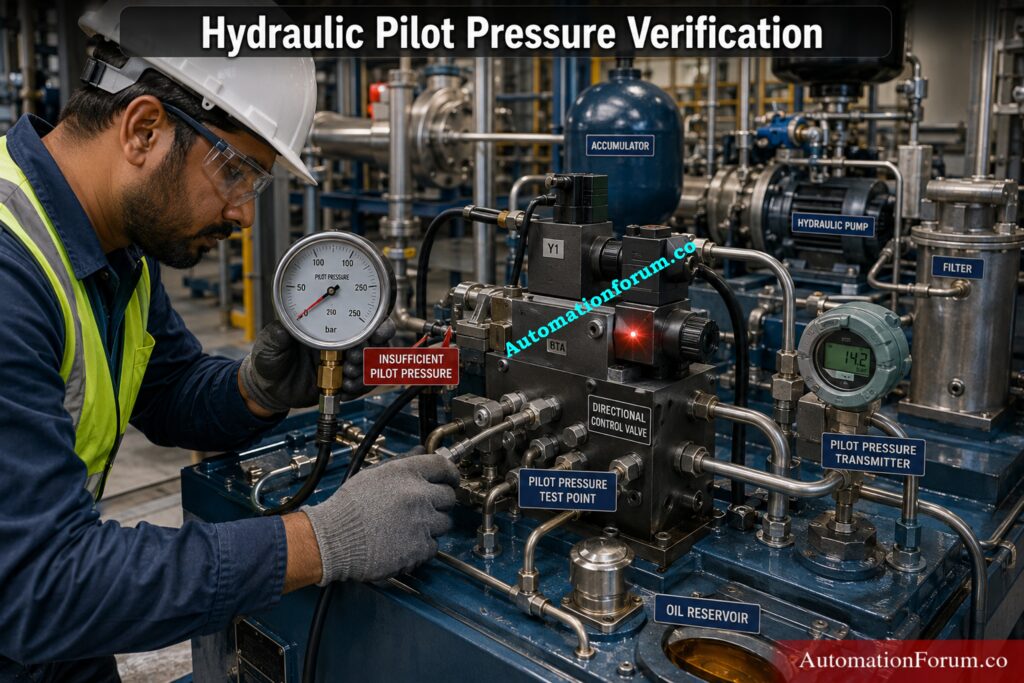
Electrical testing does not prove good valve operation.
Measure:
- Main hydraulic pressure (MPa)
- Pilot pressure
- Return line pressure
Compare measurements to hydraulic schematic and equipment design values.
Often the pilot operated directional valves do not switch from their typical position with the solenoid fully engaged . This is often the result of insufficient pilot pressure.
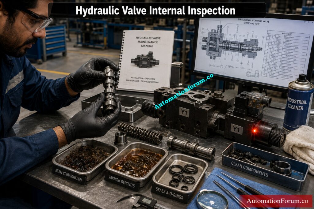
Step 11: Inspect the Valve Internally
Remove the valve only after isolating the hydraulic system to the plant lockout and tagout procedures, if all electrical tests are satisfactory.
Look for:
- Sticking spool
- Rust
- Metal particles
- Varnish deposits
- Damaged springs
- Worn seals
- Internal scoring
Use certified hydraulic cleaning solutions and lint free cloth to clean components. Replace any worn parts as needed before reassembling.
Step 12: Perform Functional Testing
After reassembly:
- Restore hydraulic pressure.
- Energize the solenoid.
- Observe spool movement.
- Verify actuator travel.
- Confirm pressure response.
- Check for leaks.
- Cycle the valve several times.
Document all readings and update maintenance records for future reference.
Track Down Every Loop Fault With Proven Field Methods: 4-20 mA Loop Troubleshooting with Loop Calibrators : A Practical Guide
Instrumentation Tests Every Engineer Should Perform
| Instrumentation Test | Purpose | How to Perform | What the Results Indicate |
| Digital Multimeter Testing | Verify electrical supply and coil health | Measure supply voltage, coil resistance, continuity, and terminal voltages. Always measure voltage with the circuit energized and under load. | Detects incorrect supply voltage, open or shorted coils, poor continuity, and hidden voltage drop problems. |
| Clamp Meter Testing | Verify coil current without disconnecting wiring | Measure the operating current while the solenoid is energized and compare it with the manufacturer’s rated current. | Low current indicates voltage drop, poor connections, or incorrect coil. High current indicates a shorted or damaged coil. |
| Insulation Resistance Testing | Check insulation integrity | Use an insulation resistance tester between the coil winding and earth (where applicable). | Low insulation resistance indicates moisture ingress, contamination, or deteriorated insulation. |
| Voltage Drop Testing | Identify hidden electrical resistance | Measure voltage across relay contacts, connectors, cables, and terminal blocks while the valve is energized. | Excessive voltage drop indicates loose terminals, worn relay contacts, damaged cables, or corroded connections. |
| Continuity Testing | Verify wiring integrity | Test continuity of field cables, connectors, neutral conductors, and terminal wiring using a multimeter. | Open circuits indicate broken wires, loose terminals, or faulty connectors. |
| Current Measurement | Confirm adequate coil power | Measure the operating current supplied to the solenoid coil during normal operation. | Abnormal current suggests incorrect coil rating, damaged wiring, or deteriorated coil windings. |
| Oscilloscope Testing | Analyze switching signals | Observe pulse width modulation (PWM), switching frequency, and output waveform in electronically controlled hydraulic systems. | Identifies distorted waveforms, unstable PWM signals, and electronic driver faults. |
| PLC Online Diagnostics | Verify PLC output operation | Use PLC programming software to monitor digital output status, forcing conditions, diagnostics, interlocks, module health, and communication status. | Confirms whether the PLC is correctly issuing the valve command or if software logic is preventing operation. |
| Output Card Diagnostics | Evaluate PLC output module health | Review built-in diagnostics available in PLC or Remote I/O modules. | Detects open circuits, overloads, short circuits, and output channel faults. |
| Relay Contact Inspection | Verify relay performance | Inspect relay contacts for pitting, discoloration, overheating, and measure contact resistance if necessary. | High contact resistance or damaged contacts can prevent sufficient current from reaching the solenoid. |
| Terminal Voltage Measurement | Trace voltage through the control circuit | Measure voltage at every terminal from the PLC output to the solenoid connector. | Quickly identifies loose terminals, poor joints, damaged cables, and voltage loss locations. |
| Pressure Transmitter and Pressure Gauge Verification | Confirm hydraulic pressure accuracy | Compare installed pressure transmitter readings with a calibrated pressure gauge. | Identifies faulty pressure transmitters, incorrect pressure feedback, or actual hydraulic pressure loss. |
Think You Can Diagnose Every Valve Failure Correctly Today?: Solenoid Valve Troubleshooting – Advanced Quiz for Instrumentation Professionals
Hydraulic Problems That Mimic Electrical Faults
| Hydraulic Problem | Typical Symptoms | How to Verify | Recommended Action |
| Low Hydraulic Pressure | Solenoid energizes but actuator does not move | Measure system pressure using a calibrated pressure gauge | Repair pump, restore oil level, or correct pressure setting |
| Blocked Hydraulic Filters | Slow or no actuator movement | Check filter differential pressure or inspect filter element | Replace clogged hydraulic filters |
| Pump Failure | Low pressure and insufficient oil flow | Measure pump pressure and flow rate | Repair or replace the hydraulic pump |
| Relief Valve Malfunction | Pressure cannot build despite pump running | Check relief valve pressure setting and operation | Adjust, repair, or replace the relief valve |
| Pilot Pressure Loss | Pilot-operated valve fails to shift | Measure pilot pressure at the valve inlet | Restore pilot pressure and inspect pilot circuit |
| Oil Contamination | Intermittent valve operation or sticking spool | Perform hydraulic oil cleanliness analysis and inspect filters | Replace contaminated oil and filters, flush the hydraulic system |
| Sticky Valve Spool | Valve operates manually but not consistently electrically | Remove valve and inspect spool movement | Clean spool, remove deposits, or replace damaged components |
| Internal Leakage | Weak actuator force or incomplete stroke | Perform pressure holding or leakage tests | Replace worn seals or repair the valve |
| Air Entrapped in Hydraulic System | Jerky, delayed, or erratic actuator movement | Inspect for foaming oil and bleed trapped air | Bleed the hydraulic system and repair suction leaks |
| Incorrect Oil Viscosity | Slow response during cold start or unstable operation at high temperature | Compare oil grade with manufacturer recommendations and check oil temperature | Replace with the correct hydraulic oil grade |
| Blocked Pilot Passage | Coil energizes but main spool remains stationary | Inspect and clean pilot ports and internal passages | Remove blockage and flush pilot circuit |
| Valve Body Corrosion | Intermittent spool movement or sticking | Inspect valve body internally during maintenance | Clean corrosion or replace the valve body if damaged |
Key Takeaway
Many hydraulic problems will look like electrical problems such as a powered solenoid that doesn’t move its actuator. Therefore, electrical measurements should not be the sole method that engineers use. In any case, before replacing any part, a full diagnosis should be made by combining instrumentation control circuit testing, PLC diagnostics and hydraulic pressure verification. This systematic approach saves unnecessary system downtime and prevents the replacement of wrong parts, and increases the overall reliability of the system.
Stop Choosing The Wrong Valve For Critical Industrial Applications: Essential Checklist for Selecting the Right Solenoid Valve for Your Application
PLC and Control Circuit Troubleshooting for Hydraulic Solenoid Valves
| PLC & Control Circuit Check | What to Verify | How to Verify | Recommended Action |
| PLC Digital Output | Output status, channel health, diagnostics, output current, Remote I/O communication | Check PLC online diagnostics and measure output voltage under load | Repair the output module or correct PLC logic if faults are found |
| Relay Interface Circuit | Relay contacts, coil voltage, socket condition, loose wiring, overheating | Measure relay input/output voltage and inspect contacts | Replace faulty relays, clean contacts, and tighten wiring connections |
| Safety Interlocks & Permissives | Emergency stop, pressure switch, pump running status, guard switches, process permissives | Monitor PLC logic and verify all interlock signals are active | Reset interlocks and correct faulty safety circuits or logic |
| Feedback Signals | Proximity switches, limit switches, reed switches, valve position feedback | Compare field signals with PLC online status | Adjust, repair, or replace faulty feedback devices and wiring |
| Control Circuit Wiring | Output card terminals, terminal blocks, fuses, connectors, junction boxes, solenoid connector | Perform voltage and continuity checks throughout the circuit | Repair damaged wiring, replace blown fuses, and tighten loose terminals |
| Loop Checking | PLC logic, relay operation, solenoid energization, valve shifting, actuator movement | Perform a complete loop check from PLC output to field device | Correct wiring or logic issues and document test results for maintenance records |
Know Exactly Which Valve Configuration Delivers Better Performance Always: Understanding 3/2-Way vs 5/2-Way Solenoid Valves (SOVs)
Real Industrial Case Study: Solenoid Valve Energized but Not Actuating
In an automotive manufacturing company, a hydraulic press continually halted during a pressing cycle. Operators stated that the PLC output to the directional control valve was still ON and the solenoid indication lamp was ON and the HMI showed no alerts. But the indications were there and the hydraulic cylinder would not extend.
The maintenance crew suspected a bad hydraulic directional valve and began preparations to replace it. The instrumentation engineer used a systematic troubleshooting method before removing the valve.
The measured coil voltage was 24.1 VDC and this confirmed the PLC output and power supply were healthy . Coil resistance was measured at 42 Ω, consistent with the manufacturer’s specification. The manual override did move the spool and lengthen the cylinder . This proved the hydraulic pump , actuator and main spool were working perfectly .
Further research found that the pilot pressure gauge was reading just 1.8 bar, when the hydraulic drawing specified a minimum pilot pressure of 5 bar. Inspection of the pilot circuit revealed a pilot filter partially obstructed with tiny metallic particles from typical component wear.
Once the filter had been changed, the pilot line was flushed and the pilot pressure restored to 5.4 bar, the directional valve shifted immediately after energising. The machine ran several production cycles without any interruptions.
The study showed that an active solenoid does not guarantee that the valve moves. Confirming electrical operation first before looking at pilot pressure avoided wasteful valve replacement, decreased downtime and eliminated recurrence failures through effective root cause analysis.
Every Engineer Should Recognize These Valve Failure Warning Signs: Common problems in Solenoid Valve & its Solutions
Common Mistakes Engineers Should Avoid During Solenoid Valve Troubleshooting
It will save a lot of maintenance time and unnecessary equipment replacement by avoiding typical troubleshooting blunders.
- Hydraulic valve electrical testing before replacement.
- Voltage measurement without loading the circuit.
- Ignoring the voltage loss across relay contacts and terminals.
- If the indicator lamp lights, you can assume that the valve is working correctly.
- Ignoring pilot pressure readings on pilot actuated valves.
- Disregarding pollution of the hydraulic oil and blocked pilot passageways.
- Failure to test manual override before removing valve.
- Failure to check field wiring before replacing PLC output card
- Using an incorrect replacement coil voltage or power rating.
- Troubleshooting without electrical drawings and hydraulic diagrams.
- Ignoring loose terminal blocks and bad ground connections.
- Documentation of repairs and corrective measures after repairs.
Understand How Directional Valves Control Every Hydraulic Motion Efficiently: What is a directional control valve and what are the types of DCV
Frequently Asked Questions About Solenoid Valve Energized but Valve Not Actuating
Why is my solenoid valve energized but not actuating?
An energized coil does not necessarily mean the spool will move, because low voltage, pilot pressure loss, contamination or PLC interlocks might all hinder actuation. Before replacing parts, check the electrical control circuit and the hydraulic system.
What could be the reasons why my solenoid valve isn’t actuating?
Common causes are: wrong voltage, broken wiring, bad relay connections, bad coil, sticky spool, blocked pilot passageways, or low hydraulic pressure. Use a systematic troubleshooting procedure to determine the actual fault.
What are some common problems with hydraulic solenoid valves?
Typical problems with hydraulic solenoid valves are sticky spools, oil contamination, burned coils, leaking seals, blocked pilot channels and faulty electrical connections. Which is why maintenance is good. Regular maintenance.
What are the common causes of solenoid valve failure?
Solenoid valve failure is commonly caused by coil overheating, incorrect supply voltage, contaminated hydraulic oil, corrosion, severe vibration and worn internal components. Proper installation and preventive maintenance prolong service life.
How do I know if a solenoid valve is working or not?
Check coil voltage, current and resistance and listen for clicking sound and spool or actuator movement. If electrical values are correct, but valve will not shift, check the hydraulic system.
What are the first signs of solenoid failure?
Initial symptoms include intermittent operation, delayed actuation response, humming noise, overheating, weak magnetic force and failure to shift from time to time. Early attention to these signs can avert unplanned shutdowns.
Avoid Expensive Valve Selection Mistakes Before Your Next Project: Proportional Vs Servo Valves
How do I test a hydraulic solenoid?
Verify the supply voltage, coil resistance, operational current, and insulation resistance. Override manually and verify the hydraulic and pilot pressure. Compare all readings to manufacturer specs.
How do I solve a solenoid valve problem?
Before removing the valve, begin with visual examination, electrical testing, PLC diagnostics, relay checks and hydraulic pressure tests. Do not make any changes until you have identified the root reason.
Can a PLC output show ON while the valve does not operate?
Yes, a bad output card, damaged relay contacts, unsecured wiring or voltage drop can keep enough current from the solenoid. Always check voltage and current at the coil under load.
How do I activate a solenoid valve manually?
Follow This Proven Procedure For Error Free Pressure Loop Testing: Method Statement for Loop Checking of Pressure Transmitter Loop
Practical Takeaways for Instrumentation and Maintenance Engineers
To troubleshoot a Solenoid Valve Energized but Valve Not Actuating error, a systematic method including PLC diagnostics, electrical tests, instrumentation checks and hydraulic pressure verification is required. Do not replace components until you have found the root problem.
Structured troubleshooting methods, preventive maintenance and adequate documentation save downtime, increase equipment dependability and extend the service life of hydraulic control systems.
Refer the below link for the Cold and Hot Loop Checking in Automation: Key Differences and Step-by-Step Procedures
