
- Understanding Rotameter Calibration and Flow Measurement
- What Is Rotameter Calibration?
- Rotameter Calibration Setup and Required Equipment
- Rotameter Calibration Calculation Formula
- Step by Step Rotameter Calibration Calculation
- Rotameter Percentage Error Calculation: Formula and Example
- Rotameter Calibration Data Table
- How to Plot and Interpret a Rotameter Calibration Curve
- Common Rotameter Calibration Problems and Troubleshooting
- Best Practices for Rotameter Calibration in Process Plants
- Frequently Asked Questions About Rotameter Calibration
- Key Takeaways for Accurate Rotameter Calibration
Understanding Rotameter Calibration and Flow Measurement
Accurate flow measurement is critical for process stability, product quality and reliable plant operation. Rotameters are a simple and affordable way to monitor liquid or gas flow in many industrial applications. However, its indicated measurement is not necessarily the actual flow under working conditions.
A practical rotameter calibration computation provides a means for instrumentation professionals to compare the reported flow to a reference measurement based on a known volume and measured collecting time. This comparison can uncover discrepancies in measurements, faulty installation, float movement issues, and different fluid characteristics.
The computation will be beneficial for maintenance personnel, commissioning engineers and control engineers while verifying instruments, troubleshooting and during preventative maintenance. This tutorial describes the calibration setup, important formulas, worked examples, computation of errors, data recording and interpretation of results.
Discover The ISO Calibration Standards Every Industrial Engineer Needs: ISO Standards For Instrumentation Calibration Complete Guide for Industrial Engineers
What Is Rotameter Calibration?
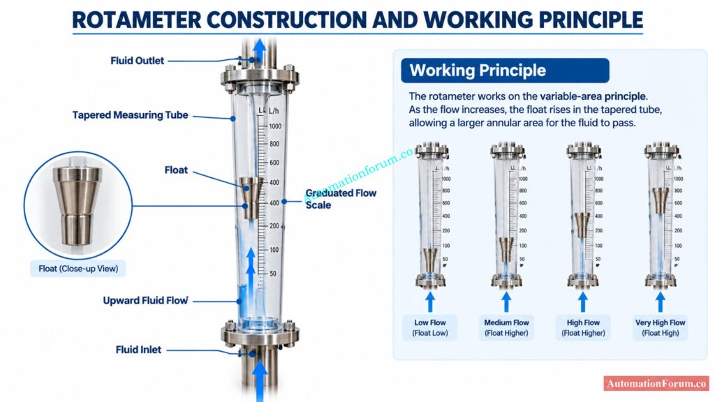
The rotameter, or variable area flowmeter, measures flow using a float in a tapered tube set vertically. The float rises as the fluid flows through the tube until the forces on it are balanced. Its position corresponds to the flow rate displayed on the scale.
The reading relies on the meter’s design and calibration settings. The result can be affected by fluid density, viscosity, temperature, pressure, installation orientation and kind of fluid.
It is crucial to distinguish between calibration, verification and adjustment. Verification establishes that the indication of the rotameter is in agreement with an appropriate reference within defined acceptance criteria. Calibration establishes the relationship between the indicated value and the reference value under stated conditions. Adjustment changes the instrument response when the design permits it. A measuring tank test may be appropriate for a practical check, but a formal calibration requires a suitable measurement procedure, documented results and consideration of measurement uncertainty and traceability requirements.
Stop Mixing Up Calibration And Verification In Industrial Instrumentation: Calibration Vs Verification: Key Differences, Procedures, Examples and Best Practices In Process Industries
Rotameter Calibration Setup and Required Equipment
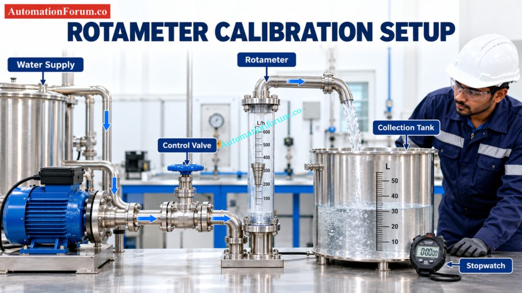
The calibration arrangement consists of the following equipment.
- Pump or fluid supply: Provides a continuous flow through the test arrangement.
- Control valve: Regulates the flow to establish the required test points.
- Rotameter under test: Indicates the flow rate to be checked.
- Measuring tank: Collects a measurable volume of liquid.
- Stopwatch: Measures the time required to collect the selected volume.
- Piping and fittings: Connect the equipment and maintain a leak free flow path.
Let the flow stabilize and then take a reading of the float position. Collect the liquid without any splashing, leaking or air trapped which may impair the measurement. Read tank volume carefully. Repeat readings as applicable.
For higher accuracy requirements, a suitable gravimetric method using a calibrated weighing system may be preferable. The reference equipment must have appropriate accuracy for the intended test.
Refer the below link for the Variable Area Flow Meter (Rotameter): Principle, Working, Selection & Applications
Rotameter Calibration Calculation Formula
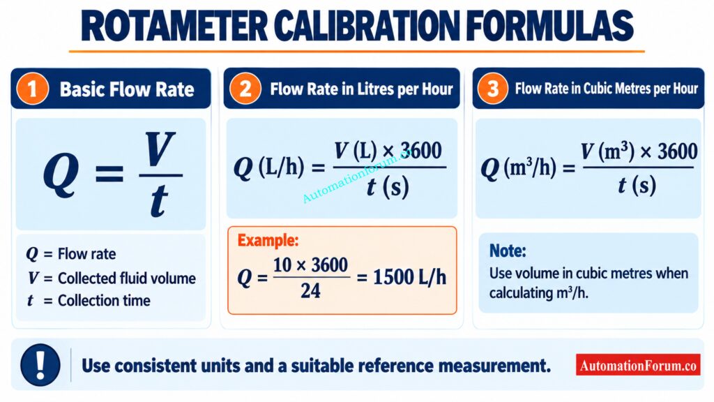
The actual flow rate through a rotameter can be calculated by collecting a known volume of liquid and measuring the time required to collect it.
Prevent Hidden Analyzer Failures With This Critical Inspection Guide: Running Inspection Procedure for Analyzer and Sampling System in Process Industries
Actual Flow Rate Formula Using a Measuring Tank
Basic formula:
Actual Flow Rate = Collected Volume ÷ Collection Time
For volume measured in litres and time measured in seconds, use the following formula to calculate the flow rate in litres per hour.
Actual Flow Rate (L/h) = (Collected Volume × 3600) ÷ Collection Time
Where:
- Actual Flow Rate: Reference flow rate calculated from the collected liquid.
- Collected Volume: Volume of liquid collected in litres.
- Collection Time: Time taken to collect the liquid in seconds.
- 3600: Conversion factor used to convert seconds into hours.
Calculate Flow Meter Turndown Limits Before Costly Selection Mistakes: Turndown Ratio Calculator for Flow Meters and Process Instruments
Flow Rate Conversion From L/s to L/h
For volume measured in cubic metres and time measured in seconds, use:
Actual Flow Rate (m³/h) = (Collected Volume × 3600) ÷ Collection Time
Make sure the volume unit used in the calculation matches the required flow rate unit.
Discover Exactly How Rotameters Measure Flow Inside Industrial Systems: What is a rotameter and how does it work
Step by Step Rotameter Calibration Calculation
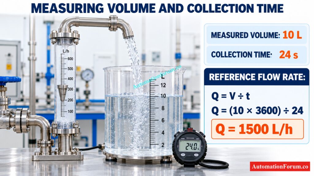
Consider the following example of a rotameter calibration check.
| Parameter | Value |
| Collected volume | 10 L |
| Collection time | 24 seconds |
| Rotameter indicated reading | 150 L/h |
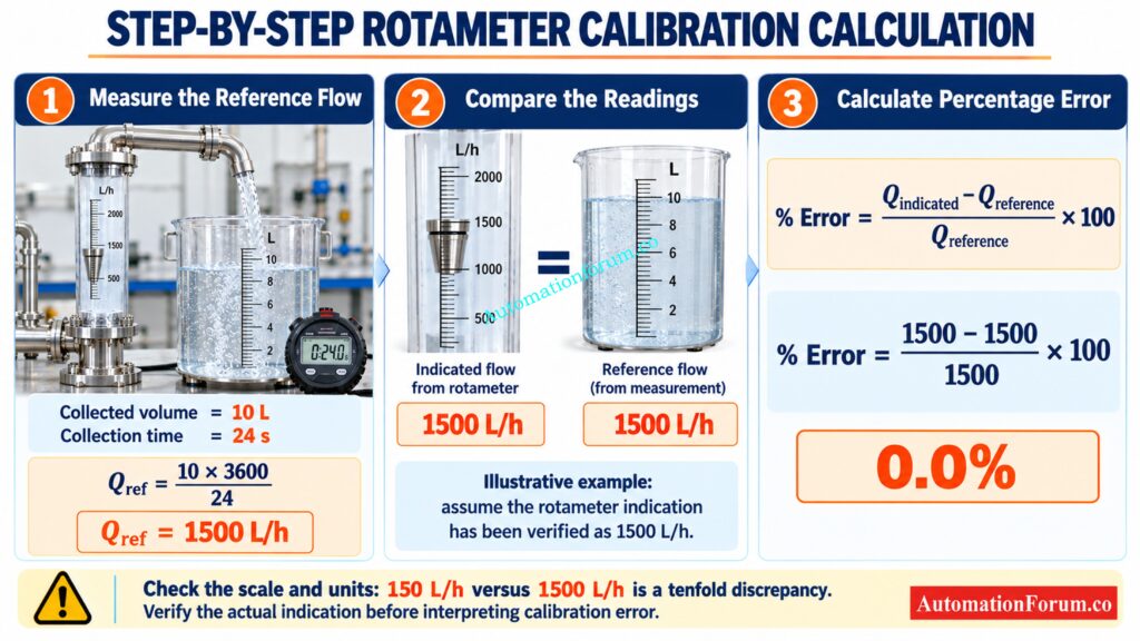
Step 1: Calculate the Reference Flow Rate
Use the formula:
Actual Flow Rate (L/h) = (Collected Volume × 3600) ÷ Collection Time
Substitute the measured values:
Actual Flow Rate = (10 × 3600) ÷ 24
Actual Flow Rate = 1500 L/h
The reference flow rate calculated from the collected volume and collection time is 1500 L/h.
Eliminate These Common Calibration Mistakes Before They Damage Accuracy: Top 15 Common Calibration Mistakes in Industrial Instruments
Step 2: Compare Indicated Flow With Reference Flow
The rotameter indication is 150 L/h, while the computed reference flow is 1500 L/h.
The readings are a factor of ten apart. Before interpreting the result, check the scale, units, decimal place and the indication recorded.
For a successful comparison, the indicated flow rate and the reference flow rate must be in the same units and use the same basis of measurement. The rotameter indicates 150 L/h but the calculated reference flow rate is 1500 L/h. The tenfold disparity must be probed by verifying the scale, units, decimal location and the recorded reading.
For illustration only, the next calculation assumes a verified indication of 1500 L/h. This assumption does not establish that the original rotameter is accurate.
Avoid Expensive Flow Meter Selection Mistakes With Turndown Analysis: Why Turndown Ratio is Important when Selecting a Flow Meter ?
Step 3: Calculate Rotameter Percentage Error
Use the following formula:
Percentage Error (%) = [(Indicated Flow Rate − Reference Flow Rate) ÷ Reference Flow Rate] × 100
Where:
- Indicated Flow Rate Flow rate indicated by the rotameter.
- Reference Flow Rate: Flow rate determined by the volume collected and the time of collection.
Substitute the values:
Percentage Error = [(1500 − 1500) ÷ 1500] × 100
Percentage Error = 0.0%
This result shows that the computed reference flow rate at this test location is equal to the indicated flow rate. It does not indicate the overall accuracy of the rotameter over its whole operating range.
Calibrate Absolute Pressure Transmitters Correctly With This Stepwise Method: Step-by-Step Procedure to Calibrate an Absolute Pressure Transmitter
Rotameter Percentage Error Calculation: Formula and Example
Assume the reference flow rate is 1000 L/h and the rotameter reads 1020 L/h.
Given Data:
- Reference flow = 1000 L/hour
- Indicated flow = 1020 L/hr
Calculation:
Percentage Error (%) = [(Indicated Flow Rate − Reference Flow Rate) ÷ Reference Flow Rate] × 100
Percentage Error (%) = [(1020 − 1000) ÷ 1000] × 100
Percentage Error = +2.0%
The positive error means that the rotameter is reading 2% higher than the standard flow rate. A negative error means that the rotameter reading is less than the reference.
The final acceptance decision must be based on the manufacturer’s specified accuracy, the uncertainty of the reference measurement, and the approved plant calibration procedure. There is no single acceptance tolerance applicable to every rotameter.
Stop Confusing Validation With Calibration—Understand The Critical Differences: Differences Between Validation and Calibration
Rotameter Calibration Data Table
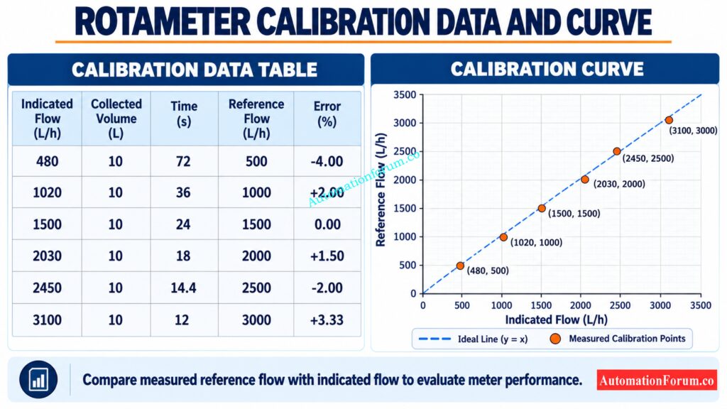
Absolute deviation = Indicated flow rate minus reference flow rate.
| Point | Indicated flow (L/h) | Volume (L) | Time (s) | Reference flow (L/h) | Deviation (L/h) | Error (%) |
| 1 | 480 | 10 | 72 | 500 | −20 | −4.00 |
| 2 | 1020 | 10 | 36 | 1000 | +20 | +2.00 |
| 3 | 1500 | 10 | 24 | 1500 | 0 | 0.00 |
| 4 | 2030 | 10 | 18 | 2000 | +30 | +1.50 |
| 5 | 2450 | 10 | 14.4 | 2500 | −50 | −2.00 |
| 6 | 3100 | 10 | 12 | 3000 | +100 | +3.33 |
Absolute deviation shows the difference between the indicated and reference flow rates in L/h, while percentage error expresses that difference relative to the reference flow rate. The values shown here are examples, not actual findings from testing on any given instrument. Compare the results to the manufacturers accuracy specification and the uncertainty of the reference measurement.
For every place the reference flow is determined from the collected volume and time and the error is calculated with the same sign convention.
Record the fluid, temperature, pressure if applicable, instrument identification, reference equipment identification, calibration status and date of test. Testing at low, medium and high flow reveals variances over the useable range.
Refer the below link for the Internal Audit Checklist for ISO Process Instrument Calibration in Process Industries
How to Plot and Interpret a Rotameter Calibration Curve
Plot the suggested flow rate on the horizontal axis and the reference flow rate on the vertical axis. Plot the ideal line when the two values are equal.
Curve close to the ideal line shows satisfactory agreement between the suggested and reference flow rates at tested places. If you plot the indicated flow on the horizontal axis and the reference flow on the vertical axis, a point above the ideal line shows that the reference flow is higher than the shown flow. A point below the ideal line signifies that the shown flow is higher than the reference flow. If the deviations are always the same, that could indicate a systematic error in the measurement. If the deviations change across the range, that could indicate non-linearity or other measurement difficulties. Before evaluating if the rotameter satisfies its acceptance criteria, perform repeat measurements to check for consistency and consider reference measurement uncertainty.
Repeatability can be determined by repeating the measurements at the same flow point. A calibration curve is good for looking at trends, but it does not tell you about accuracy unless you have measurement uncertainty and stated acceptance criteria.
Avoid Dangerous Re-Ranging Errors That Compromise Instrument Accuracy: Why Calibration Isn’t the Same as Re-ranging in Process Instrumentation
Common Rotameter Calibration Problems and Troubleshooting
| Problem | Possible cause and corrective action |
| Float sticks erratic or moves | Look for contaminants, deposits, or mechanical damage. Clean only as instructed by the manufacturer. |
| Reading Changes post-installation | Check for verticality and stability of installation. |
| Flow fluctuates during test | Stabilize supply and analyze pump pulsation or control valve instability. |
| Collected volume is wrong | Collection and reading procedure. Check graduations on tank. |
| The timing findings differ | Repeat the measurement using an appropriate timing device. |
| Leakage occurs | Check connections and correct leaks before testing |
| Reading changes with fluid properties | Check density, viscosity, temperature and pressure against the calibration basis of the meter. |
| Float or tube is damaged | Remove the meter from service when necessary and arrange inspection or replacement. |
| Reading differs by a large factor | Verify scale units, float reading position, range, and decimal placement. |
| Flow appears reversed or absent | Verify inlet and outlet connections and the manufacturer’s installation requirements. |
Never dismantle or adjust a rotameter while it is connected to a hazardous or pressurized process. Follow established procedures for isolation, depressurization and fluid management.
Improve Flow Transmitter Accuracy With This Essential Calibration Guide: differential pressure flow transmitter calibration.
Best Practices for Rotameter Calibration in Process Plants
- Check the range of the instrument, units of scale and intended service before testing.
- Use reference equipment that is sufficiently accurate and has a valid calibration status.
- Allow the flow and the correct process conditions to stabilize.
- If necessary repeat measurements to assess consistency
- Record results before and after any allowed adjustment .
- Specify the reference equipment, test conditions and calculating procedure.
- Compare findings to accepted acceptance criteria.
- Use correction factors in accordance with the manufacturer’s instructions.
A water calibration testing does not automatically prove the accuracy of a rotameter for some other liquid or gas. Density, viscosity, temperature and pressure variations may necessitate appropriate modifications or testing under representative operating conditions. Manufacturer guidance is particularly important for gas service.
Eliminate Instrument Calibration Errors With These Proven Field Procedures: Instrument calibration procedures.
Frequently Asked Questions About Rotameter Calibration
What is the formula for rotameter calibration calculation?
The formula is : Q = V/t Where : Q = Flow rate V = Volume collected t = Time of collection For liters and seconds use Q (L/h) = (V x 3600) / t.
How do you calculate actual flow rate using a measuring tank?
Take a known volume of liquid and find out how long it takes. Multiply the volume collected in liters by 3600 and divide by the time taken in seconds to get the flow rate in L/h.
How do you calculate rotameter percentage error?
Error (%) = [(Indicated Flow Rate − Reference Flow Rate) ÷ Reference Flow Rate] × 100. If the result is positive , the reading is higher . If the result is negative , the reading is lower .
Improve Analytical Measurement Reliability With These Essential Calibration Procedures: Analytical Instruments Calibration Procedures
Can a rotameter be calibrated using water?
Yes. If the meter and test setup is appropriate for water calibration. However, these results may not immediately apply to other fluids with varying density, viscosity, temperature or operation circumstances.
Why does a rotameter reading change with fluid density?
The forces exerted onto the float in the tapered tube depend on the density of the fluid. So changes in density can change the link between float position and real flow rate.
Master Control Valve Calibration Before Process Control Performance Suffers: Control Valve Calibration Procedures
How often should a rotameter be calibrated?
Calibration frequency is based on manufacturer recommendations, process criticality, operating conditions, and the outcomes of past calibrations. Follow plant maintenance schedule and change interval as performance history warrants.
What is the difference between rotameter calibration and verification?
Verification compares the indicated flow with a proper reference measurement. Calibration sets the link between indication and reference value. Adjustment modifies the instrument response when allowed.
How can a rotameter calibration curve help maintenance?
A calibration curve displays the relationship of indicated flow to reference flow at various test locations. Identification of measurement discrepancies, probable non-linearity and changes in the equipment performance.
How do you calibrate a rotameter?
Stabilize the flow, collect a known volume of liquid, measure the time of collection and calculate the reference flow rate. Compare with the rotameter reading and assess the inaccuracy against the established acceptance standards.
Master Accurate Flow Measurement Through Proven Calibration Techniques: How to calibrate flow measurement devices
How to calculate rotameter flow rate?
For a measuring tank test: Flow Rate (L/h) = Volume collected in L x 3600 / Collection time in seconds Compare the estimated value with the indicated reading to determine the deviation of measurement.
How does a rotameter measure flow?
A rotameter measures flow via the position of a float in a vertically-mounted tapered tube. As you increase flow , you normally increase the float . At some point the forces on the float will balance out .
What is the unit of a rotameter?
Common rotameter flow units include liters per hour (L/h), liters per minute (L/min), cubic meters per hour (m³/h) and milliliters per minute (mL/min). The appropriate unit is determined by the scale and service of the instrument.
What do rotameters measure?
Rotameters are used to measure the volumetric flow rate of liquids or gasses. The measurements depend on the design of the meter, the properties of the fluid, and the conditions of calibration.
Achieve Reliable Temperature Measurements With This Practical Calibration Procedure: Temperature Calibration Procedure
What is the working principle of a rotameter?
A rotameter operates on the variable area concept, with a float moving in a tapered tube with varying flow. The float position is the flow rate as read on the corresponding calibrated scale.
How to check rotameter flow?
Stabilize the process flow and watch the position of the float relative to the graduated scale. Where possible, validate the indication by a suitable reference method, e.g. by collecting a known volume of liquid during a measured duration.
What is the formula for flow?
The basic formula for volumetric flow is Q = V / t where Q is flow rate , V is volume , and t is time . I just want to say that my life has changed for the better because of your work.
What are the different types of rotameters?
Common forms are glass tube rotameters, metal tube rotameters and plastic tube rotameters. They are also categorized by the type of connection, the indication mechanism, and whether they incorporate electrical flow indication or transmission.
Explore Essential Calibration Standards Every Instrumentation Engineer Should Know: ISO Standard Calibration Procedures for Flow Measuring Instruments
Key Takeaways for Accurate Rotameter Calibration
A good rotameter calibration calculation begins with a good reference flow measurement and a clear comparison to the stated value. Proper unit translation, % error calculation, repeat measurements and documentation assist instrumentation specialists detect measurement errors before they impair process performance.
https://automationforum.co/calibration-interval-schedule-process-instrumentation/Check the scale of the meter and conditions of calibration before interpreting results. Use the appropriate reference equipment, follow the manufacturer’s instructions and accept the instrument only when the results fulfill the necessary requirements.
Refer the below linked or the Calibration Interval Schedule Procedure for Process Instrumentation Using Risk-Based Method
