- Who Uses the Restriction Orifice Sizing Tool ?
- When Should Restriction Orifice Sizing Tool be Used?
- How to Use this Restriction Orifice Sizing Tool Effectively?
- Download link for Restriction Orifice Sizing Excel Tool
- Restriction Orifice Design Steps
- Restriction Orifice Standards
- Inputs for Restriction Orifice Design
- Factors for Sizing Restriction Orifice
The Sizing of Restriction Orifices Tool is an essential tool for engineers and technical teams involved in industrial process design, optimization, and troubleshooting. This Excel-based form provides organized calculations, reference data, and guidance for precisely sizing restriction orifices based on process specifications. A full description of its functioning and applications is provided below.
Who Uses the Restriction Orifice Sizing Tool ?
- Process Engineers to design and analyze flow control systems, ensuring safety and efficiency.
- Instrumentation and Control Engineers use this excel to Validate compatibility with flow meters and pressure sensors; integrate restriction orifices into control systems.
- Maintenance Engineers: Diagnose flow-related issues and assess if installed orifices meet process demands.
- Used for Project Engineers to Design systems for new installations and optimize flow restrictions during commissioning phases.
When Should Restriction Orifice Sizing Tool be Used?
- To calculate the dimensions of the restriction orifice for specific operational conditions.
- For projects requiring precise flow or pressure drop control, such as chemical injection systems or steam applications.
- When modifying or upgrading existing systems to adapt to changes in operating conditions.
- To improve energy efficiency by minimizing unnecessary pressure drops.
- When irregular flow rates or unexpected pressure drops suggest issues with an orifice or flow control device.
- During audits or system health checks to confirm the restriction orifice matches design specifications.
Click here for Why Restriction Orifice is Some Distance from Blowdown Valve?
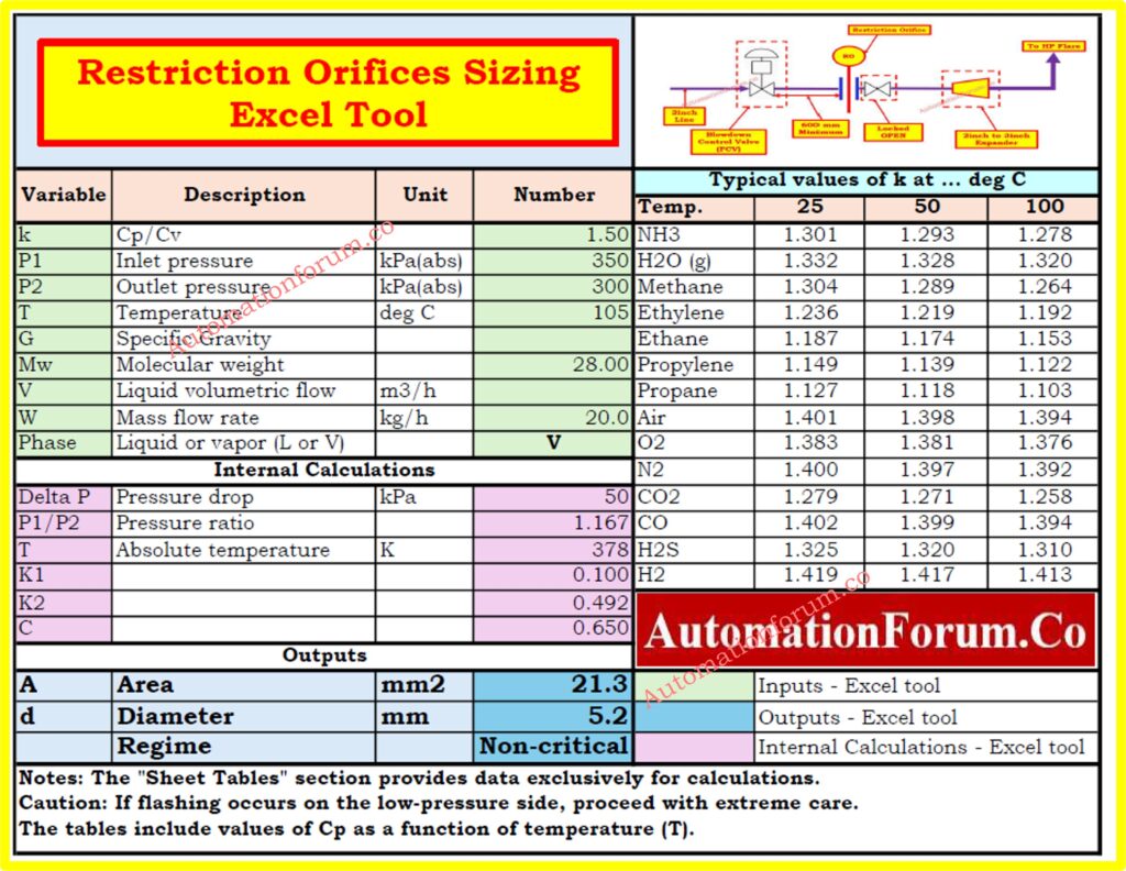
How to Use this Restriction Orifice Sizing Tool Effectively?
- Understand input parameters by opening the Orifice sheet and entering variables like k (Cp/Cv), flow rate, and pressure ratio (P1/P2). Ensure input data reflects actual or expected process conditions for accurate results.
- Use reference data from the reference Tables sheet, which includes typical k-values for different gases and temperatures and additional guidelines for correct variable selection.
- Perform calculations by reviewing computed results, such as the recommended restriction orifice size, and validating outputs against system requirements for compatibility.
- Interpret results by matching the output to available orifice dimensions and ensuring they meet safety margins and efficiency requirements.
- Document and report design choices using the tool’s outputs, creating reports for stakeholders and attaching supporting calculations to meet regulatory or internal standards.
Click here for Control Valve P1 and P2 vs. Flow Excel Designing Tool (Downloadable)
Download link for Restriction Orifice Sizing Excel Tool
This tool is a valuable tool for those working in the process industry. It delivers the knowledge required to make informed decisions while creating new systems, optimizing existing ones, or troubleshooting
To start using the Sizing of Restriction Orifices Tool, click the link below to download:
Click here for more Instrumentation Excel Tools Resource
Click here for 200+ Online Instrumentation Calculators Collections
Restriction Orifice Design Steps
- Identify the purpose of the RO, whether for pressure control or flow control, and evaluate the operating conditions (critical or sub-critical).
- Gather relevant data such as pressure, temperature, flow rate, and fluid properties.
- Perform sizing calculations based on ISO 5167 standards, either by a design engineer or vendor.
- Validate essential design elements like cavitation index (Kc=0.93), pressure drop, minimum orifice diameter, and piping space constraints.
- Update P&ID and fill out RO datasheets with all necessary information.
Refer the below link for the Orifice Plate Flow and Pressure Drop Calculation Excel Tool
Restriction Orifice Standards
There are no direct standards for designing restriction orifices, but the following references are commonly used:
- ISO 5167 Part 1 and Part 2
- ISA RP 3.2
- API RP 550/551
- API 2531
- IEC 60534-8-3
- API Manual of Petroleum Measurement – Chapter 4
- AGA Report No. 3
- API MPMS 14.3.2
- ISO 5024
- ISO 5168
Inputs for Restriction Orifice Design
The following inputs are essential for RO design:
- PFD and P&ID
- Hydraulic calculation sheet
- PMS (Piping Material Specification)
- Operating conditions: upstream and downstream pressure, temperature, flow rate, line size, density, viscosity, molecular weight, Cp/Cv, vapor pressure, etc.
Factors for Sizing Restriction Orifice
- Due to the Pressure Drop, determines the required thickness of the RO device. It must be carefully calculated for safety and efficiency.
- The restriction orifice is sized for normal flow rates; critical ROs require downstream flow rates to be considered.
- Avoid choked or sonic flow conditions that generate excessive noise and vibrations, leading to mechanical failure. Use multi-stage ROs for larger pressure drops.
- Prevent cavitation by ensuring the cavitation index is below the incipient cavitation index. Design must consider inlet pressure, outlet pressure, and vapor pressure.
- Noise due to pressure reduction can be minimized by:
- Reducing pressure drop.
- Using multi-stage reduction or multi-hole RO plates.
- Optimizing pressure drop distribution across stages.
- Increasing the safety margin between cavitation and incipient cavitation indices.