
- Why Is Temperature Switch Calibration Important?
- Types of Temperature Switches Used in Process Industries
- Tools Required for Temperature Switch Calibration
- Safety Precautions Before Temperature Switch Calibration
- Step by Step Calibration Procedure for Temperature Switch
- Calibration Principle for Temperature Switch
- Prepare the Calibration Setup for Temperature Switch
- Dry Bath Calibrator Procedure
- Recording Calibration with Repeatability Checks
- Temperature Switch Set Point, Reset Point and Hysteresis
- Completion of Calibration
- Temperature Switch Calibration Calculation and Example
- Temperature Switch Repeatability Testing
- Temperature Switch Calibration Report
- Common Temperature Switch Calibration Problems
- Temperature Switch Calibration Standards and Traceability
- FAQ on Temperature Switch Calibration
Temperature switch calibration is an important activity in industrial instrumentation and process automation. Temperature switches are used to monitor process temperature and activate alarms, interlocks, shutdown systems, and equipment protection functions when the temperature reaches a specified limit.
Incorrect temperature switch calibration can cause unwanted alarms, delayed equipment shutdown, or failure to detect abnormal process temperatures.
This article explains how to calibrate a temperature switch using a dry block temperature calibrator, reference thermometer, standard thermocouple, and digital multimeter. It covers set point verification, reset point measurement, hysteresis calculation, repeatability testing, troubleshooting, and calibration report preparation.
What is a temperature switch?
A temperature switch is an instrument that changes its electrical contact state when the measured temperature reaches a predetermined set point.
Depending on its design, the switch may open or close an electrical contact when the temperature increases or decreases.
Temperature switches are commonly used in:
- High temperature alarms.
- Low temperature alarms.
- Pump and compressor protection.
- Process equipment shutdown systems.
- Boiler and heater protection.
- Industrial machinery temperature monitoring.
- Emergency shutdown and interlock applications.
Temperature switches are available in mechanical, electronic, and electronic sensor based designs.
Why Is Temperature Switch Calibration Important?
Temperature switch calibration verifies whether the instrument operates at its specified trip and reset temperatures.
Regular calibration helps to:
- Maintain reliable shutdown and interlock operation.
- Verify the specified temperature trip point.
- Confirm the reset temperature.
- Check switch differential and hysteresis.
- Identify contact malfunction.
- Verify repeatability.
- Reduce unwanted process alarms.
- Improve equipment protection.
Types of Temperature Switches Used in Process Industries
High Temperature Switch (TSH)
A high temperature switch activates when the process temperature rises above its specified set point.
For example, a high temperature switch configured at 100°C may change its contact state when the temperature reaches approximately 100°C.
Low Temperature Switch (TSL)
A low temperature switch activates when the process temperature falls below its specified set point.
For example, a low temperature switch configured at 10°C may change its contact state when the temperature decreases to approximately 10°C.
The actual switching direction and contact arrangement depend on the instrument configuration.
How to Calibrate Temperature Switch
Tools Required for Temperature Switch Calibration
Prepare the following instruments and accessories before starting calibration.

- Calibrated dry block temperature calibrator.
- Calibrated reference thermometer.
- Standard reference thermocouple.
- Digital multimeter with continuity and resistance measurement.
- Thermocouple sockets and connectors.
- Test probes and connecting leads.
- Appropriate thermowell or temperature insert.
- Necessary hand tools.
- Soft cleaning cloth.
- Calibration report template.
The reference thermometer and temperature calibrator must have suitable ranges and accuracy for the required calibration tolerance.
Safety Precautions Before Temperature Switch Calibration
Follow these precautions:
- Verify the temperature switch tag number against the instrument datasheet.
- Inform the control room operator before starting maintenance.
- Identify whether the switch is connected to an alarm, interlock, or ESD system.
- Apply the approved isolation and lockout procedures.
- Allow the process connection and sensing element to reach a safe temperature before removal.
- Verify that the instrument is safely isolated from process pressure and hazardous energy.
- Disconnect the electrical connections only after following the approved procedure.
- Use suitable PPE.
- Store the removed temperature switch safely.
Important: Never disconnect or bypass a temperature switch used in an ESD or equipment protection system without the required authorization and compensating safeguards.
Step by Step Calibration Procedure for Temperature Switch
This below Step by Step procedure includes instructions for calibrating a temperature switch using a thermometer and a dry bath temperature calibrator.
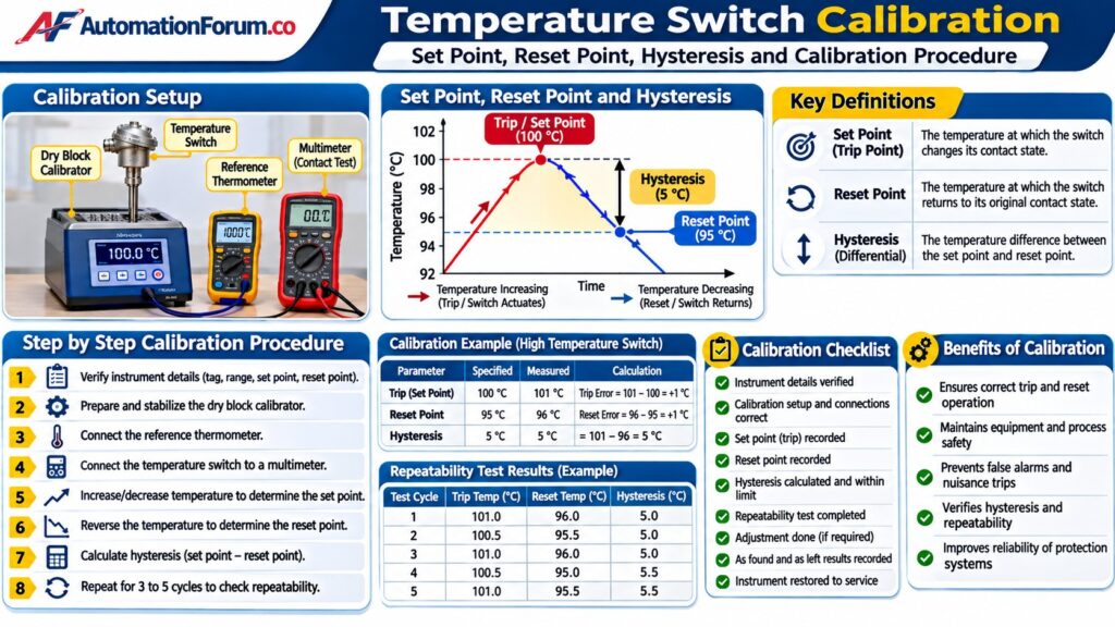
Verify Instrument Details
Before starting calibration, check the following details from the instrument datasheet:
- Instrument tag number.
- Temperature switch type.
- Temperature range.
- Specified trip point.
- Specified reset point.
- Contact configuration.
- Normally open or normally closed condition.
- Required calibration tolerance.
Record the as found condition before making any adjustment.
Calibration Principle for Temperature Switch
Tools for calibrating and validating temperatures include dry-blocks. For heating or cooling temperature sensors, such thermocouples or RTDs, to known and accurate temperatures, they offer a stable and uniform environment. This makes it feasible to calibrate and test temperature-measuring equipment.
Prepare the Calibration Setup for Temperature Switch

- Collect the required equipment, including a dry bath calibrator, a thermowell of the right size for a temperature switch, a thermometer with the appropriate range and accuracy, a power source, a standard thermocouple, and the probes and connectors needed to attach the temperature switch to the calibrator and thermometer.
- Ensure sure the temperature switch and calibrating test equipment are clean of any debris or residue that might affect the calibration’s precision.
- Plug the dry bath calibrator into an electrical socket to turn it on.Verify the correct operation of the dry bath calibrator and the accuracy of the temperature control.
- As you place the temperature switch into the dry bath calibrator with the suitable thermowell, make sure the sensing element is entirely submerged in the bath and not touching the walls or bottom of the container.

- Connect the temperature switch to the multimeter in continuity or resistance mode using the appropriate probes and leads. Verify the leads, probes, and temperature switch are in fine shape, and that the connection is stable.
- To measure the temperature of the dry bath calibrator, insert the standard reference thermocouple with a standard thermometer in the same location as the temperature switch. Verify the thermometer’s accuracy and resolution to ensure they are appropriate for the calibration process and that it has been calibrated.
- The temperature displayed by the dry bath calibrator should be compared to the reading from the standard thermometer.
- The setup is ready for calibration of the temperature switch if the thermometer and dry bath calibrator are steady and the temperatures coincide.
Dry Bath Calibrator Procedure
- Before making any adjustments, check the current settings of the temperature switch to make sure they are already within the proper temperature range.
- Verify that all of the connections are correctly secured.
- By referencing the instrument data sheet, you may verify a number of temperature switch parameters. Typical settings are the tag number, type, number of contacts utilized, setpoint, and reset values.
- Turn on the multimeter and choose either the resistance or continuity mode. Adjust the dry bath temperature calibrator step by step increments to the temperature switch set point.
- Never go above the temperature range of the temperature switch; always read the handbook to find out the precise range.
- Increase the temperature gradually until it is within the operating range of the temperature switch, then wait for it to stabilize.
- The temperature should be ramped up across the nominal operating range of the temperature switch very gradually.
- The temperature should be recorded using a normal thermometer whenever the output of the temperature switch changes state (from the specified setpoint).
- Gradually ramp the temperature in the opposite way until the temperature switch changes the state (reset point). Record the temperature that a typical thermometer displays.
- Compare the readings acquired during calibration to the expected values of the temperature switch. If there are significant variations, adjust the temperature switch as necessary.
- Make small adjustments and check the temperature measurement after each one to make sure you are not crossing over the appropriate set point.
- Adjust the temperature switch setpoint until the required temperature is reached for the switch contacts to open and close.
- Before beginning, please read the manufacturer’s instructions since the calibration process may be different depending on the specific temperature switch.
Recording Calibration with Repeatability Checks
- Apply inputs that correspond to the temperature switch’s set and reset points in the direction of temperature changes from the test standards five to six times to verify the repeatability of the temperature switch.
- If the output contact change over the value of the temperature switch does not fall within an acceptable range, calibration is required.
- Again, if the output contact change overvalues exceed the permitted range, the temperature switch has to be repaired or replaced.
- There is no need for additional calibration if all of the output contacts change over values (+/-%) fall within accepted limits.
- The output contact change over values should be recorded in the blank calibration report’s as found/as left column.
Temperature Switch Set Point, Reset Point and Hysteresis
Three important parameters must be understood during temperature switch calibration.
Set Point
The set point is the temperature at which the switch changes its electrical contact state during the specified temperature direction.
Reset Point
The reset point is the temperature at which the switch returns to its original contact state when the temperature moves in the opposite direction.
Hysteresis
Hysteresis is the difference between the trip temperature and reset temperature.
For example, consider a high temperature switch with a trip point of 100°C and a reset point of 95°C.
Hysteresis = 100 − 95
Hysteresis = 5°C

Completion of Calibration
- When the calibration has been successfully finished, attach the calibration label on the temperature switch.
- When the calibration is complete, clean the apparatus, store it somewhere safe, and make a note of the temperature switch calibration data for later use.
- The thermowell should be carefully removed without damaging nearby equipment.
- The dry bath calibrator should be disconnected.
- Return the temperature switch in the processing area to its original position.
- Make sure the calibration area is clean.
- De-isolate the apparatus.
- Return the temperature switch’s bypassed or inhibited signal to its usual level.
- Make sure the temperature switch is working properly before returning it into use.
Temperature Switch Calibration Calculation and Example
Consider the following high temperature switch calibration example.
| Parameter | Specified value | Measured value |
| Trip temperature | 100°C | 101°C |
| Reset temperature | 95°C | 96°C |
Step 1: Calculate trip point error
Trip point error = Measured trip point − Specified trip point
= 101 − 100
= +1°C
Step 2: Calculate reset point error
Reset point error = Measured reset point − Specified reset point
= 96 − 95
= +1°C
Step 3: Calculate measured hysteresis
Measured hysteresis = 101 − 96
= 5°C
Step 4: Calculate specified hysteresis
Specified hysteresis = 100 − 95
= 5°C
The measured hysteresis is equal to the specified hysteresis. However, both trip and reset points are 1°C higher than their specified values.
The final acceptance decision must be based on the instrument datasheet and approved calibration tolerance.
Temperature Switch Repeatability Testing
Repeatability testing verifies whether the temperature switch produces consistent trip and reset values over repeated calibration cycles.
The following is an example observation table.
| Test cycle | Trip temperature | Reset temperature | Hysteresis |
| 1 | 101°C | 96°C | 5°C |
| 2 | 100.5°C | 95.5°C | 5°C |
| 3 | 101°C | 96°C | 5°C |
| 4 | 100.5°C | 95°C | 5.5°C |
| 5 | 101°C | 95.5°C | 5.5°C |
Review the variation between the cycles and compare it with the permitted repeatability specification.
Poor repeatability may indicate mechanical wear, contact deterioration, sensor problems, temperature instability, or an unsuitable test setup.
Temperature Switch Calibration Report
A calibration report should contain all information necessary to identify the instrument and evaluate its performance.
Record the following details:
- Technician and reviewer details.
- Instrument tag number.
- Instrument manufacturer and model.
- Temperature range.
- Specified trip point.
- Specified reset point.
- Reference equipment identification.
- Reference equipment calibration status.
- Calibration date.
- As found trip and reset values.
- As left trip and reset values.
- Hysteresis results.
- Repeatability observations.
- Adjustment details.
- Acceptance status.

You can get the Excel template that was used to construct the temperature switch calibration report by clicking the link below.
Common Temperature Switch Calibration Problems
| Problem | Possible cause | Recommended action |
| Switch does not trip | Incorrect wiring or defective contact | Check contact continuity and wiring |
| Incorrect trip temperature | Set point adjustment or sensor drift | Verify using the reference thermometer |
| Incorrect reset point | Differential adjustment issue | Check differential setting |
| Unstable contact switching | Temperature instability or poor thermal contact | Verify immersion and temperature stability |
| Poor repeatability | Mechanical wear or sensor deterioration | Repeat testing and inspect the switch |
| Contact does not reset | Damaged contact mechanism | Inspect and replace if necessary |
| Different readings between cycles | Incorrect test setup or thermal gradients | Verify reference sensor position and stabilization |
Temperature Switch Calibration Standards and Traceability
Temperature switch calibration should follow the instrument manufacturer’s instructions, approved plant calibration procedures, and specified acceptance requirements.
The following references are relevant to temperature measurement and calibration:
- ITS-90: International Temperature Scale of 1990, used as a basis for temperature measurement traceability.
- ISO/IEC 17025: Specifies general requirements for the competence of testing and calibration laboratories.
- Manufacturer documentation: Provides instrument specific set point, differential, accuracy, and adjustment requirements.
- Plant calibration procedures: Define approved calibration methods, test intervals, acceptance criteria, and reporting requirements.
ISO/IEC 17025 is a laboratory competence standard, not a universal temperature switch calibration procedure.
Use reference equipment with suitable calibration status and measurement uncertainty for the required test tolerance.
FAQ on Temperature Switch Calibration
What is the standard for temperature switch calibration?
There is no one standard that works for calibrating temperature switches. However, best practices say that calibration must be done against reference standards that can be traced back to globally recognized benchmarks like ITS-90. It must also follow ISO/IEC 17025-accredited methods to make sure that the results are accurate and can be traced back.
How often should you calibrate a temperature switch?
It is a good idea to calibrate temperature switches at least once a year, but this may happen more often, such as every six months or every three months, depending on how often the sensors are used, the conditions in which they are used, how important they are, or what the manufacturer says.
What is the standard for temperature calibration?
Temperature calibration should use defined physical values, like the triple point of water at 0.01 °C, the melting point of gallium, or the freezing points of certain metals, and it should follow the International Temperature Scale of 1990 (ITS-90) to make sure it is consistent and can be compared.
ISO/IEC 17025 accreditation guarantees traceable calibration, environmental control, and adequate documentation, which boosts accuracy and trust in the sector.
How to reset a temperature switch?
Depending on the situation, “resetting” can mean two different things:
Calibration reset: For wireless temperature sensors like IoT devices, you usually reset to default calibration through the device’s portal. To do this, select the sensor, go to the “Calibrate” page, click Default, and then apply the new measurement.
Factory or hardware reset: For some thermostat sensors, taking out the battery for a few minutes or putting in a new one might reset the unit.
What is the standard procedure for temperature switch calibration?
Use a calibrated temperature source, reference thermometer, and multimeter to verify the trip point, reset point, hysteresis, and repeatability against the instrument specification.
What is the difference between trip point and reset point?
The trip point is where the switch changes contact state, while the reset point is where it returns to its original contact state.
What is hysteresis in a temperature switch?
Hysteresis is the temperature difference between the switch trip point and reset point.
How often should a temperature switch be calibrated?
The interval depends on instrument criticality, operating conditions, manufacturer recommendations, plant maintenance policy, and historical performance.
Which equipment is used for temperature switch calibration?
Common equipment includes a dry block calibrator, reference thermometer, standard thermocouple, digital multimeter, and suitable test connections.
How do you test a high temperature switch?
Gradually increase the temperature until the contacts change state, record the trip point, and then decrease the temperature to determine the reset point.
How do you test a low temperature switch?
Gradually decrease the temperature until the contacts change state, record the trip point, and then increase the temperature to determine the reset point.
Why is repeatability testing important?
Repeatability testing verifies that the switch operates consistently at similar temperatures during repeated heating and cooling cycles.
What is an as found calibration result?
It is the measured condition of the temperature switch before any adjustment or repair is performed.
What is an as left calibration result?
It is the final measured condition after adjustment or maintenance, showing whether the instrument meets the required acceptance criteria.
