
Pressure Drop Calculator
Impulse Tubing · Darcy-Weisbach · Swamee-Jain Friction Factor
Impulse Line Schematic
Unit System
Fluid Properties
Tubing Properties
Flow Rate & Fittings
Pressure Drop Results
| Parameter | Value |
|---|
- What Is Pressure Drop in an Impulse Tube
- Why Is Impulse Tubing Pressure Drop Important in Instrumentation
- How Does the Impulse Tubing Pressure Drop Calculator Work
- Darcy Weisbach Equation for Impulse Line Pressure Drop
- How Is Reynolds Number Used in Impulse Tubing Pressure Drop Calculation
- How Does the Swamee Jain Equation Calculate Friction Factor
- Input Parameters Used in the Impulse Tubing Pressure Drop Calculator
- How to Use the Impulse Tubing Pressure Drop Calculator
- How to Interpret Impulse Tubing Pressure Drop Calculator Results
- Example of Impulse Line Pressure Drop Calculation
- Factors That Increase Pressure Drop in Impulse Tubing
- Practical Impulse Line Design Considerations for Instrument Engineers
- Metric and Imperial Unit Support
- Frequently Asked Questions About Impulse Tubing Pressure Drop
- Conclusion: Impulse Tubing Pressure Drop Calculator
Pressure loss in an impulse line is easy to overlook during instrumentation design, especially when the tubing is short and the flow rate is small. In practice, however, tubing diameter, length, fluid properties, flow rate, fittings, surface roughness, and elevation can all influence the pressure reaching a pressure transmitter or differential pressure transmitter.
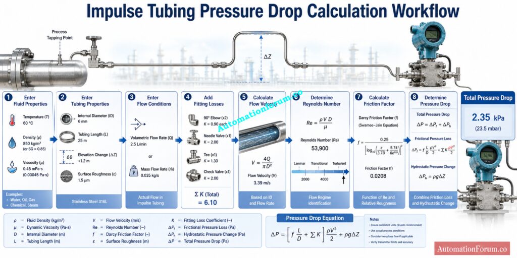
The Impulse Tubing Pressure Drop Calculator provides a practical way to estimate this pressure change. It uses the Darcy Weisbach relationship and a Swamee Jain approach for friction factor calculation. The calculator also considers Reynolds number, tubing roughness, fittings, flow velocity, friction loss, hydrostatic pressure change, and total pressure drop.
Stop Frozen Impulse Lines Before They Damage Measurement Accuracy: Impulse Line Freezing Risk and Heat Tracing Calculator for Instrumentation Engineers
What Is Pressure Drop in an Impulse Tube
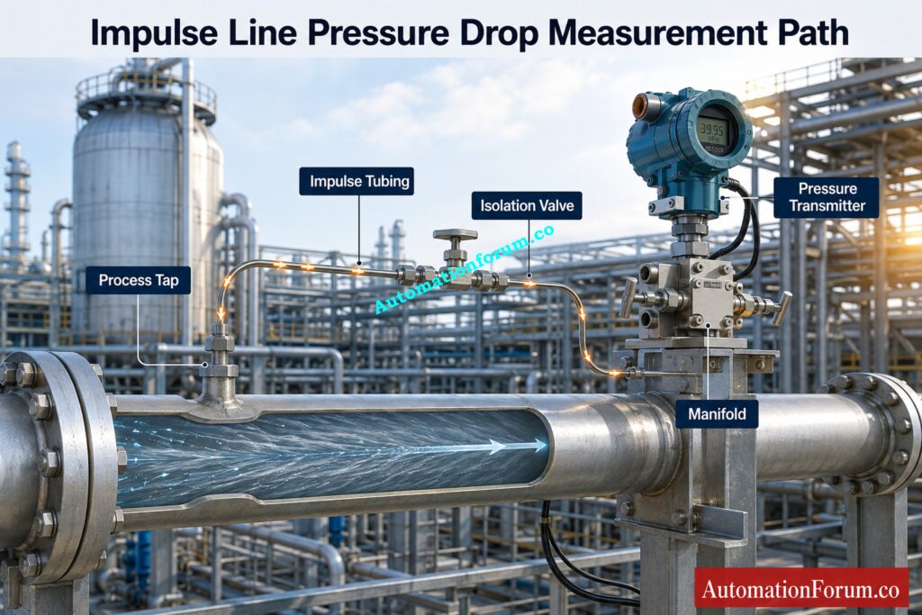
What Causes Pressure Drop in Impulse Tubing
An impulse tube carries process pressure from a tapping point to an instrument. As fluid moves through the tubing, pressure can be lost because of wall friction and fittings. The pressure can also change because of elevation.
Frictional Pressure Loss and Hydrostatic Pressure Change
These two effects should be considered separately.
Frictional pressure loss depends mainly on tubing length, internal diameter, fluid density, viscosity, velocity, surface roughness, and fittings. The change in hydrostatic pressure is dependent on the density of the fluid, the gravity, and the variation in elevation.
The calculator combines these effects to determine the total pressure drop.
Test Your Impulse Line Knowledge Before Field Installation: Advanced Quiz on Impulse Line Installation in Process Industries
Why Is Impulse Tubing Pressure Drop Important in Instrumentation
Effect of Pressure Drop on Pressure Transmitter Measurement
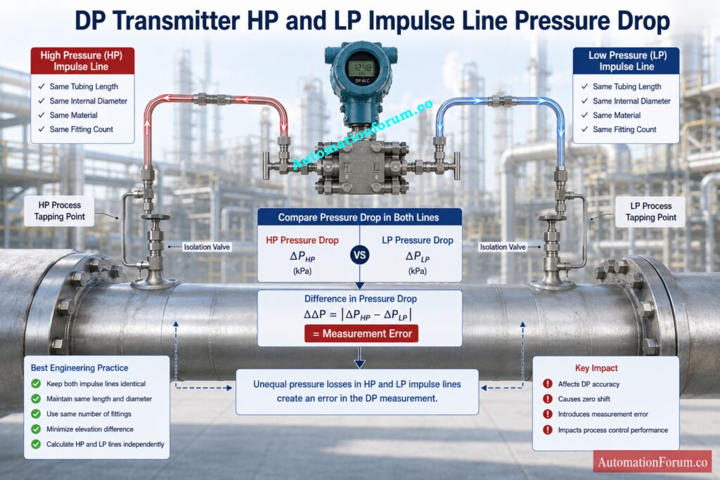
For a pressure transmitter, pressure loss between the process connection and the instrument changes the pressure available at the transmitter. For a differential pressure transmitter, the issue becomes more important because the high pressure side and low pressure side can experience different pressure losses.
Effect of Pressure Drop on Differential Pressure Transmitters
If both impulse lines have different lengths, internal diameters, materials, fitting arrangements, or flow characteristics, their pressure losses may not be equal. The calculator specifically recommends evaluating the high pressure and low pressure lines independently because the difference between their pressure drops can contribute to measurement error.
How Unequal Impulse Line Pressure Loss Can Cause Measurement Error
Impulse tubing pressure drop can also influence response characteristics. A practical design therefore considers pressure loss together with installation conditions, process requirements, accessibility, plugging risk, condensation, vapour pockets, freezing, vibration, and applicable project specifications.
How Does the Impulse Tubing Pressure Drop Calculator Work
What Does the Impulse Tubing Pressure Drop Calculator Calculate
The calculator first establishes the fluid and tubing conditions. It then determines flow velocity and Reynolds number before calculating the friction factor.
The major results include total pressure drop, flow velocity, Reynolds number, flow regime, Darcy friction factor, relative roughness, frictional pressure loss and hydrostatic pressure change.
Metric and Imperial Pressure Drop Calculation
The calculator can be used in both metric and imperial systems. Inputs for the metric system include millimeters, meters, kilograms per cubic meter and kilopascals. Imperial inputs are inches, feet, pounds per cubic foot, and psi.
Refer the below link for the Instrument Range Calculator | Calculate Span, Rangeability, Turndown Ratio & Calibration Range
Darcy Weisbach Equation for Impulse Line Pressure Drop
Darcy Weisbach Pressure Drop Formula
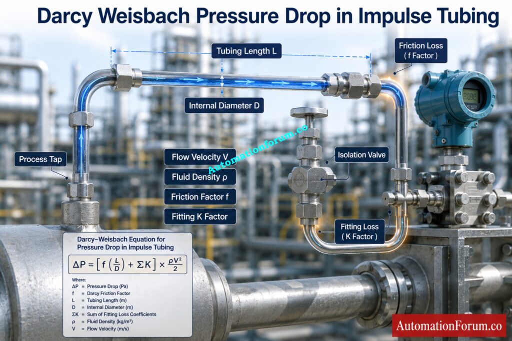
The friction component follows the Darcy Weisbach relationship:
ΔP = [f(L/D) + ΣK] × ρV² / 2
Here, ΔP represents friction and fitting pressure loss. The Darcy friction factor is represented by f. Tubing length is L, internal diameter is D, density is ρ, and velocity is V. The total fitting loss is represented by ΣK.
How Tubing Length and Internal Diameter Affect Pressure Loss
The calculator uses the tubing length to diameter relationship directly. This is important because a long tubing run combined with a small internal diameter can create considerably more friction loss than a short run with a larger internal diameter. The calculator source confirms that friction and fitting losses are calculated together using the length to diameter relationship and the total K factor.
Choose Tube Dimensions That Protect Pressure Measurement Accuracy: How to Select the Right Impulse Tube Size for Pressure Measurement Systems
How Is Reynolds Number Used in Impulse Tubing Pressure Drop Calculation
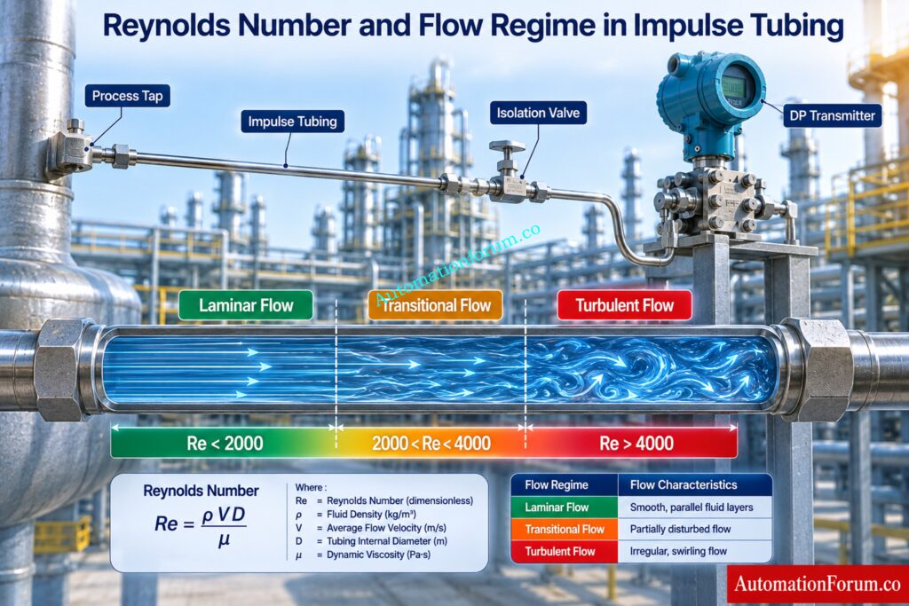
Reynolds number helps identify the flow condition inside the impulse tube.
The calculator uses these ranges:
Laminar Flow in Impulse Tubing
Reynolds number below 2000 is treated as laminar flow. For this condition, the calculator uses the relationship:
f = 64 / Re
Transitional Flow in Impulse Tubing
A Reynolds number between 2000 and 4000 is treated as transitional flow. The calculator uses the Swamee Jain based friction factor approach for this region.
Turbulent Flow in Impulse Tubing
A Reynolds number above 4000 is treated as turbulent flow. The calculator again uses the Swamee Jain approach.
This is useful because viscosity has a stronger influence in laminar conditions, while Reynolds number and surface roughness become important when flow becomes turbulent.
Prevent Costly Tubing Leaks With Proper Pressure Testing: Method Statement for Pressure Test and leak Test for Instrument Tubing and Impulse line
How Does the Swamee Jain Equation Calculate Friction Factor
What Is the Swamee Jain Equation
The Swamee Jain equation provides a practical approximation for friction factor without requiring an iterative solution of the Colebrook relationship.
Friction factor is influenced by Reynolds number and relative roughness. Relative roughness is determined from absolute surface roughness divided by tubing internal diameter.
How Tubing Roughness Affects Friction Factor
Tubing condition therefore matters. Smooth drawn tubing generally produces a different friction characteristic from rougher or deteriorated tubing. The calculator provides material selections and also allows direct roughness input.
Avoid Installation Mistakes That Destroy Impulse Measurement Reliability: Best Practices for Impulse Tubing Installation
Input Parameters Used in the Impulse Tubing Pressure Drop Calculator
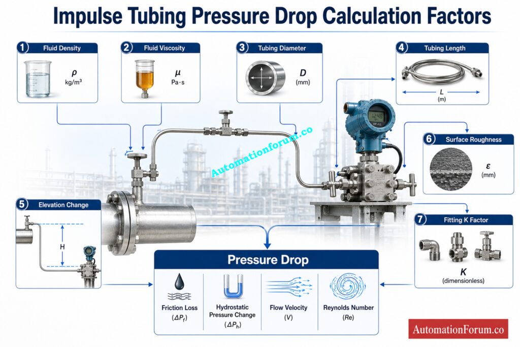
Fluid Temperature
Temperature is provided as an operating reference. The engineer should use fluid density and viscosity that represent the actual operating condition as closely as practical.
Fluid Density and Specific Gravity
Density can be entered directly, or the user can select specific gravity as the input method. This makes the calculator useful when fluid data is available as either density or specific gravity.
Dynamic Viscosity and Kinematic Viscosity
Dynamic viscosity describes the fluid resistance to flow and is entered in cP. Kinematic viscosity relates viscosity to density and can be entered in cSt. The calculator supports both approaches.
Impulse Tubing Internal Diameter
Use the actual internal diameter rather than outside diameter. Internal diameter directly affects flow area and velocity.
A smaller internal diameter gives a smaller flow area. For the same flow rate, velocity increases and frictional pressure loss can increase significantly.
Impulse Tubing Length
Enter the total straight tubing length. Longer tubing provides greater frictional resistance, so accurate length is important for instrumentation impulse tubing design.
Elevation Change
Elevation can be positive or negative depending on the direction of the line. The calculator determines hydrostatic pressure change using density, gravitational acceleration, and elevation difference.
Tubing Material and Surface Roughness
The calculator provides roughness options for stainless steel drawn tubing, copper tubing, plastic tubing, new commercial carbon steel, corroded or galvanized carbon steel, and cast iron. Direct roughness input is also available.
Volumetric Flow Rate and Mass Flow Rate
You can enter either volumetric flow rate or mass flow rate. The calculator converts the selected input into the flow velocity required for the pressure loss calculation.
K Factor for Fittings
Elbows, valves, tees, and other fittings add local pressure loss. Instead of entering every fitting separately, the calculator uses a total K factor representing their combined effect.
Get Expert Answers To Critical Impulse Line Questions: Instrument Impulse Line: Most Common Questions and answers
How to Use the Impulse Tubing Pressure Drop Calculator
- Select the metric or imperial unit system.
- Enter the fluid temperature and local gravitational acceleration.
- Select direct density or specific gravity.
- Select dynamic viscosity or kinematic viscosity.
- Enter the actual tubing internal diameter.
- Enter the total tubing length.
- Enter the elevation change.
- Select the tubing material or enter absolute roughness directly.
- Select volumetric flow rate or mass flow rate and enter the value.
- Enter the total K factor for fittings.
- Calculate the pressure drop.
- Check total pressure drop, friction loss, hydrostatic pressure change, velocity, Reynolds number, friction factor, relative roughness and flow regime.
Fix These Dangerous Impulse Line Problems Before Failure: What are Impulse lines? – Impulse line problems and solutions
How to Interpret Impulse Tubing Pressure Drop Calculator Results
Total pressure drop: This is the combined result of friction and hydrostatic effects.
Frictional pressure loss: This shows the pressure loss associated with tubing friction and fittings.
Hydrostatic pressure change: This represents the pressure change created by elevation.
Flow velocity: This indicates how quickly the fluid moves through the tubing.
Reynolds number: This identifies the calculated flow regime.
Flow regime: The result indicates laminar, transitional, or turbulent flow.
Darcy friction factor: This represents the resistance associated with the calculated flow condition and tubing roughness.
Relative roughness: This relates tubing surface roughness to internal diameter.
A negative total result does not automatically mean an error. It can occur when the hydrostatic component is negative and greater in magnitude than the frictional component, resulting in a net pressure gain in the direction defined by the entered elevation.
Calculate Air Pressure Loss Before Designing Instrument Headers: Instrument Air Header Pressure Drop Calculator for EPC Instrumentation Design
Example of Impulse Line Pressure Drop Calculation
Consider a water like fluid with density of 998 kilograms per cubic metre and dynamic viscosity of 1 cP.
Use these inputs:
Internal diameter: 6.35 mm
Tubing length: 3 m
Elevation change: minus 0.5 m
Volumetric flow rate: 2 L/min
Total fitting K factor: 4
The engineer can enter these values directly into the calculator. The resulting flow velocity is approximately 1.05 m/s and the Reynolds number is approximately 6650, placing the flow in the turbulent region.
Using the calculator relationships, the friction and fitting losses are approximately 11.3 kPa. The hydrostatic component is approximately minus 4.89 kPa. The resulting total pressure drop is therefore approximately 6.4 kPa.
This example shows why elevation should not be ignored. The downward elevation component reduces the net pressure loss calculated from friction and fittings.
Select The Correct Cable Gland Before Installation Begins: Instrument Cable Gland Selector Calculator Guide
Factors That Increase Pressure Drop in Impulse Tubing
Longer tubing increases frictional resistance. Smaller internal diameter increases velocity and generally increases pressure loss. Higher flow rate also increases velocity and pressure loss.
The higher viscosity may cause the resistance to increase especially in laminar flow. Greater surface roughness increases friction factor. Additional fittings increase local losses through the total K factor.
Fluid density also affects pressure loss because it appears directly in the pressure loss relationship. Elevation can either increase or reduce the total result depending on its direction.
Prevent Control Valve Failures With Proper FRL Selection: FRL Unit Selection Procedure for On Off Instrumentation Control Valves
Practical Impulse Line Design Considerations for Instrument Engineers
Choose an internal diameter appropriate for the application and avoid unnecessary tubing length. Make fittings as small as practicable and employ fluid characteristics that match the working conditions.
For differential pressure measurement, consider the high pressure and low pressure impulse lines individually. If similar line characteristics are required in the application, keeping line length, internal diameter, material and fitting arrangement consistent will assist prevent uneven pressure losses.
Pressure drop is only one part of instrumentation impulse tubing design. Engineers should also examine installation practices, accessibility, plugging risk, condensation, vapour pockets, freezing, vibration, process conditions, and project requirements.
Protect 4 To 20 mA Loops And HART Communication: Advanced HART Loop Calculator for Reliable 4 to 20 mA and HART Communication
Metric and Imperial Unit Support
The calculator supports both unit systems. Metric operation uses inputs such as mm, m, kg/m³, and kPa. Imperial operation uses inches, feet, lb/ft³, and psi.
Solve Open Tank Level Errors With Accurate DP Calculations: DP Calculator for Zero Suppression in Open Tank Level Measurement
Frequently Asked Questions About Impulse Tubing Pressure Drop
What Is Impulse Tubing Pressure Drop?
It is the change of pressure caused by friction, fittings and elevation effects as the fluid passes through impulse tube.
It helps engineers comprehend the pressure entering a pressure or differential pressure transmitter.
How is pressure drop calculated in an impulse line?
It takes into account flow velocity, reynolds number , friction factor, tube length, internal diameter, fittings and fluid characteristics.
The frictional loss and hydrostatic pressure change are then combined to determine total pressure drop.
Why is impulse tube diameter important?
Smaller internal diameter means smaller flow area and faster fluid velocity for similar flow rate.
The frictional pressure loss through the impulse tube might become rather high at higher velocities.
What is the role of Reynolds number?
The Reynolds number is used to decide if the flow is laminar, transitional or turbulent. The calculator selects the proper relation of friction factor based on the flow regime.
Why should DP transmitter impulse lines be evaluated separately?
The high pressure and low pressure impulse lines can experience different pressure losses.
The difference between these losses can contribute to measurement error in differential pressure measurement.
Troubleshoot Closed Tank Level Problems Like A Pro: Step-by-Step Troubleshooting Checklist for Closed Tank DP Type Level Transmitter
What is the difference between friction loss and hydrostatic pressure change?
Friction loss is caused by fluid passing through tubing and fittings.
The hydrostatic pressure varies with the height difference between the two sites.
How do fittings affect impulse line pressure drop?
Other fittings ( elbows , valves , tees , etc . ) add to the resistance of fluid flow .
The calculator combines their effect to express it as a total K factor.
What is the formula for calculating pressure drop?
Friction and fitting losses are calculated using a fitting K factor and the Darcy Weisbach relation.
ΔP = [f(L/D) + ΣK] × ρV² / 2, with hydrostatic pressure change calculated separately.
How to calculate pressure drop in a pipe system?
Pressure drop can be calculated from fluid density, velocity, pipe length, internal diameter, friction factor, and fitting losses.
For the attached calculator, hydrostatic pressure change is also included in the total result.
How can I calculate the flow rate if I know the pressure drop in a pipe?
A known pressure drop can be used with pipe dimensions, fluid properties, friction factor, and fitting losses to determine flow rate.
The attached calculator is designed primarily to calculate pressure drop from a specified flow rate rather than solve directly for unknown flow rate.
What is the equation for pressure in a pipe?
For pressure loss caused by friction and fittings, the calculator uses the Darcy Weisbach based relationship.
Hydrostatic pressure change is calculated separately using ΔP = ρgΔh.
How much pressure drop per 100 ft of pipe?
That is because it is determined by diameter, flow rate, fluid density, viscosity, roughness and fittings. There is no single pressure drop number for every 100 ft of pipe.
Therefore the pressure drop must be computed from the real operation and the pipe size.
What is the purpose of impulse tubing?
Impulse tubing transfers process pressure from a process tapping point to an instrument such as a pressure transmitter or differential pressure transmitter.
Proper tubing design helps ensure that the pressure reaching the instrument represents the intended process condition.
How to calculate pressure transmitter?
A pressure transmitter itself is not normally calculated from impulse tubing pressure drop.
The engineer calculates the pressure reaching the transmitter and then verifies the transmitter range, process connection, installation, and measurement requirements.
What is the definition of an impulse line?
An impulse line is the tubing or piping connection that carries process pressure from a process tapping point to a pressure measuring instrument.
It forms the pressure transmission path between the process and the transmitter.
How is a pressure transmitter connected?
A pressure transmitter is connected to the process through an impulse line, normally using a process tapping point and suitable isolation and connection hardware.
For a differential pressure transmitter, separate high pressure and low pressure impulse lines connect the two process tapping points to the transmitter.
Conclusion: Impulse Tubing Pressure Drop Calculator
The Impulse Tubing Pressure Drop Calculator gives instrumentation engineers a practical way to assess pressure loss before finalising an impulse line arrangement. This calculation depends on the tubing diameter, length, fluid characteristics, flow rate, fittings, roughness and elevation. The calculator combines these elements using Darcy Weisbach pressure loss, Reynolds number, friction factor and hydrostatic pressure relationships.
Both impulse lines should be considered separately in differential pressure applications and unequal pressure losses should be given special consideration. Use the calculator as an engineering evaluation tool, but the final design should incorporate process conditions, instrument requirements, installation techniques, applicable standards and project specifications.
Refer the below link for theStep by Step Pressure Transmitter Installation Procedure
