An induction motor resembles a poly-phase transformer with a shorted secondary circuit. As a result, the initial current drawn by the primary in transformers at normal supply voltage is quite high for a brief period of time. In contrast to DC motors, there is no back emf, which results in a large beginning current. When an induction motor is turned on directly from the supply, it consumes 5 to 7 times as much current as it can handle at full load and produces only 1.5 to 2.5 times as much torque. The operation of other devices connected to the same line may be impacted by the considerable voltage drop caused by this high initial current.Therefore, starting induction motors with higher ratings—generally those above 25kW—directly from the mains supply is not recommended.
Why are induction motor starting techniques necessary?
A spinning magnetic field is created when an induction motor is powered by a three-phase AC source. This field forms a connection with the conductors of the rotor, giving it torque. An induction motor starts in this manner. However, a significant inrush current from the AC mains is needed for this process.
A specific load’s high current requirements could result in significant voltage dips in the AC distribution system. Other electrical loads connected to the same system are also affected. Even the motor windings may burn due to it. Extreme circumstances could result in a total blackout.
It can restrict the induction motor’s starting current, and that can easily avoid this issue. Thus, it can be obtained by lower the starting current to a safe value by using induction motor starting techniques.
What are the methods for starting induction motors?
To keep the beginning current within acceptable limits, a starter is used in each of the induction motor starting techniques.
In respect to a squirrel cage induction motor, the methods are:
- Autotransformer
- Primary resistors Utilization
- Stars-Delta switches
- DOL Starter Method
Applying a lower voltage to the stator in a squirrel cage motor regulates the starting inrush current. When used to start squirrel cage induction motors, these techniques are commonly referred to as decreased voltage methods.
Autotransformer Method:
Auto-starters are another name for auto-transformers. Both star connected and delta connected squirrel cage motors can use them. In effect, it is a three-phase step-down transformer with several taps that allow the user to start the motor at 50%, 65 or 80% of line voltage. When an auto-transformer is started, a current drawn from the supply line is always drawn that is equal to the transformation ratio less than the motor current.As an illustration, when a motor is started on a 65 percent tap, the applied voltage to the motor will be 65 percent of the line voltage, and the applied current will be 65 percent of the line voltage beginning value. Transformer activity is what causes the difference between the line current and the motor current. An auto-internal starter’s connections are depicted in the figure. When starting, the switch is in the “start” position, and a tap-selected decreased voltage is applied across the stator.
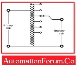
The auto-transformer automatically disconnects from the circuit as soon as the motor reaches the proper speed, let’s say up to 80% of its rated speed, and the switch is moved to the “run” position.It depends on the size of the motor whether the switch is of the air-break (for small motors) or oil-immersed (for large motors) kind. With time delay circuits on an autostarter, there are also protections for overload and no-voltage.
Advantage:
- Both star-connected motors and delta-connected motors can use this form of speed control.
- The starter’s internal losses are negligible.
- At start-up, it produces more torque.
- It is appropriate for prolonged starting times.
Disadvantage:
- The power factor is low at start-up.
- It is more expensive.
Primary Resistors Utilization Method:
Primary resistors’ main function is to lower voltage and apply it to the stator. Consider a 50% reduction in the starting voltage. The beginning current will then decrease by the same amount in accordance with Ohm’s law (V=I/R). The starting torque of a three-phase induction motor can be calculated from the torque equation as being roughly proportional to the square of the applied voltage. This indicates that the beginning torque will only be 25% of its usual voltage value if the applied voltage is 50% of the rated value. Small induction motors are frequently started smoothly using this way. For motors that need a lot of beginning torque, it is not advised to start them with primary resistors.
Resistors are typically chosen so that the motor can get 70% of the rated voltage. Full resistance is initially linked in series with the stator winding at start-up, then it gradually decreases as the motor accelerates. The resistances are removed from the circuit when the motor reaches the proper speed, and the stator phases are then directly linked to the supply lines.
Advantage:
- The motor accelerates smoothly as a result.
- This approach starts with a greater power factor.
- This approach is less expensive than the auto-transformer starter for low output loads.
Disadvantage:
- Heat is dissipated by the resistors.
- It is difficult to alter voltage using this strategy for varying loads.
Star-Delta Switches Method:
The motors, which are made to run on a delta linked stator, employ this technique. The stator winding is connected in star during start-up and in delta during regular operation using a two-way switch. The voltage over each phase of the motor will be lowered by a factor of 1/ (?3) when the stator winding is linked in a star configuration as opposed to a delta configuration. The initial or starting torque will be 1/3 more than it would be for a winding with a delta connection. A star-delta starter is therefore comparable to an autotransformer with a ratioof 1/ (?3), or 58 percent decreased voltage.

Advantage:
- This approach is economical, efficient, and effective.
- High inertia loads are appropriate for it.
- Because there are no tap changers needed, heat losses are minimal.
Disadvantage:
- Only delta-connected motors can be used with this technique.
- Voltage reductions are rigid and lack flexibility.
DOL Starter Method:
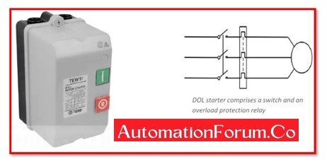
Small three phase induction motors are capable of being started “direct-on-line,” which implies that the motor is given its rated supply right away. But as was already indicated, in this case the initial current would be enormous, typically 5 to 7 times the rated current. It is anticipated that the beginning torque will be 1.5 to 2.5 times the full load torque. A DOL starter, which typically comprises of a contactor and a motor protection device like a circuit breaker, can be used to start induction motors immediately on-line. A coil-operated contactor that is managed by push buttons for start and stop makes up a DOL starter.
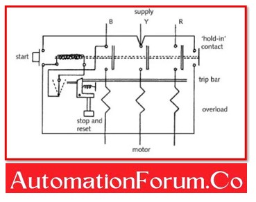
When the start push button is depressed, the contactor activates and simultaneously isolates the motor’s three phases from the supply phases. To stop the motor, press the stop push button, which de-energizes the contactor and disconnects all three phases.
For motors rated below 5kW, a DOL starter is typically utilised to prevent an excessive voltage drop in the supply line caused by high starting current.
An overvoltage, undervoltage, and thermal protection circuit are all included in this starter. As a result, the control circuit disconnects the motor from the main AC supply in the event of any irregularities. protecting the induction motor in the process.
Advantage:
- It is the starter that costs the least.
- It has a high starting torque.
- They can start the motor without any prior preparations.
Disadvantage:
- It is only appropriate for induction motors with low ratings.
- There is an increase in current stress across the motor windings.
In respect to a slip ring induction motor, the method is:
- Rotor Resistance Starter Method
Rotor Resistance Starter Method:
Slip-ring motors can be started with full line voltage because slip-rings make it simple to add external resistance to the rotor circuit. Through the use of slip-rings, a star-connected rheostat is linked in series with the rotor. The beginning current in the rotor and, consequently, in the stator will be reduced by adding resistance to the rotor current. Additionally, it enhances power factor and increases torque. The attached rheostat can be manually or automatically adjusted.
Slip-ring motors can be started on load because adding more resistance to the rotor increases the starting torque.
Each phase of the rotor circuit must have a changeable external resistance when using the Rotor Resistance Starter method. A rated voltage is applied across the motor’s terminals at start-up. The increased rotor resistance reduces the beginning current while boosting the starting torque. The resistances gradually cut off the circuit as the induction motor accelerates.
The external resistance is only used at starting and is gradually removed as the motor gains speed.
Advantage:
- It provides more starting torque.
- It provides smooth and extensive speed control.
Disadvantage:
- It is only appropriate for an induction motor with a slip ring.
- Because slip rings and brushes are present, it requires extra maintenance.
Some Useful Questions:
1. What is the importance of a DC motor’s starting method?
DC motor is stationary when it starts, and no back emf is produced. The initial current can only be controlled by armature resistance, however this high current only lasts for a brief period before decreasing as rotor speed increases then reverse the motor’s EMF. If there is a significant inrush current, a DC motor may be harmed. Additionally, voltage changes in the lines are possible. Therefore, we should employ a starting approach in order to avoid large starting current. Unless overheating causes rotor coil damage.
2. What are the different types of a single phase induction motor?
Depending on how they start, single phase induction motors are divided into different categories.
a. Split phase induction motors,
b. Shaded pole induction motors and
c. Capacitor induction motors.