- Why Do Pressure Gauges and Transmitters Sometimes Disagree?
- Step-by-Step Troubleshooting Guide
- Scenario 1: The Transmitter Is Right – Condensate in Impulse Line
- Scenario 2: The Gauge Is Right – Ground Loop Affecting Transmitter
- Maintenance and Troubleshooting Checklist
- Why Pressure Reading Accuracy Important
- Best Practices for Reliable Pressure Measurement
- Future Trends – Digital Gauges and Smart Transmitters
For safety, efficiency, and quality control in industrial plants and process industries, it is very important to be able to detect pressure accurately. One of the most common things to measure in automation is pressure. Pressure gauges and pressure transmitters are both quite popular for this purpose.
But this is a problem that almost every instrumentation expert or technician has had to deal with in the field:
A pressure gauge and a pressure transmitter are both connected to the same process tap, but they give different readings.
This makes you ask a very critical question: Which one should you trust?
It’s not as easy as declaring “the gauge is wrong” or “the transmitter is drifting.” To fix the problem, on the other hand, you need to take an organized approach. In this essay, we’ll go into great detail about:
- Why the readings on a pressure gauge and a transmitter might not match
- How to systematically fix problems with differences
- The function of calibration and reference standards
- Things that matter in the real world, such installation, impulse lines, and instrument accuracy
- Field engineers can take these practical actions to make sure measurements are accurate.
By the end, you’ll know how to firmly settle differences between these two important tools.
Pressure & Leak Testing Method Statement for Instrument Tubing and Impulse Lines: Method Statement for Pressure Test and leak Test for Instrument Tubing and Impulse line
Why Do Pressure Gauges and Transmitters Sometimes Disagree?
It appears obvious at first that two instruments linked to the same process tap should show the same pressure. But in reality, differences are common
Some important causes are:
Calibration Drift
Transmitters are electronic devices that can lose their accuracy over time, while mechanical gauges can lose their accuracy due to wear and tear or vibration.
Accuracy Class
Most of the time, gauges are accurate to within 1-2% of full scale, although transmitters can be accurate to within 0.1% or greater. This discrepancy can be big, depending on the range of pressure.
Hydrostatic Head Effect
The liquid column creates pressure discrepancies if the gauge and transmitter are at different heights.
Impulse Line Issues
If there are blockages, air pockets, or leaks in the tubing, it might cause readings to be wrong or take a long time.
Impulse Tubing Installation Best Practices for Reliable Pressure Measurement: Best Practices for Impulse Tubing Installation
Mechanical Damage
Gauges may be less accurate because of too much pressure, pulsing, or mechanical stress.
Common Pressure Gauge Measurement Errors and How to Avoid Them: Errors Involved in Pressure Gauge Measurement
Step-by-Step Troubleshooting Guide
Step 1: Isolate and Test with a Reference Standard
When it comes to metrology, the most important thing to remember is to never accept a measurement until it has been checked against a reference.
If two instruments don’t agree, the first thing to do is to compare them to a calibrated reference standard.
How to Do It:
- Take the process tap out of the system.
- Connect an outside pressure source, like a hand pump or a deadweight tester, to both the gauge and the transmitter.
- Use a digital pressure calibrator with excellent precision as a reference.
- Slowly add pressure and check the readings on all three devices at different places in the range (zero, mid-span, and full-scale).
The digital calibrator is like a “referee.” It’s possible that the gauge is out of calibration if it shows deviation. If the transmitter’s signal drifts away from the reference, it needs to be fixed or adjusted.
Instead of guessing, this exam gives a clear, objective response.
Step 2: Check Installation and Process Conditions
Sometimes the problem isn’t with the instruments themselves, but with how they are set up.
Elevation Difference
In liquid service, even a little change in height can change the readings. Hydrostatic head will cause a transmitter located 1 meter below a gauge to observe an extra 0.1 bar (around 1.45 psi).
Impulse Line Orientation
- If impulse lines are not routed correctly, they may trap air (in liquid service) or condensate (in gas/steam service).
- This causes readings that are wrong or take too long to come in.
Mechanical Stress
- If gauges are exposed to vibration or pulsating pressure, their pointers can get damaged or “flutter.”
- In these circumstances, you should put in a snubber or dampener.
Ultimate Smart Pressure Transmitter Trim & Calibration Guide with Visual Diagrams: Smart Pressure Transmitter Sensor Trim Guide with Diagrams & Calibration Steps
Step 3: Examine Installation-Related Factors
Even when the instruments are set up correctly, discrepancies in how they are installed can cause readings to be wrong.
In liquid pressure applications, a variation in height is one of the most typical causes. If the pressure gauge is higher or lower than the transmitter, a hydrostatic pressure head (or drop) is created.
For example:
- For instance, a gauge that is located below the transmitter will display a larger pressure due of the weight of the liquid column above it.
- On the other hand, if it’s mounted above, it might read a little lower.
Even modest changes in height can make a difference for water. For example, a vertical height of 10 cm is equal to around 10 mbar (0.145 psi) of pressure difference.
Other elements that affect installation are:
- Design and route of the impulse line: Signal lag or pressure loss can happen when lines are too long or not straight.
- Orientation: If a transmitter is installed wrong (such upside down), it can trap air or fluids and change the data.
- Effects of temperature: Extreme heat or cold can harm the electronics in gauge bourdon tubes or transmitters.
It’s usually a good idea to look over the installation plans and make sure that the instruments are installed appropriately, vented or drained properly, and exposed to the identical process conditions.
Step 4: Look for Blockages or Leaks
The connections between instruments are generally the weakest parts of a process system.
- Blockages: An impulse line may be partially blocked by scale, rust, or process debris, which can make one instrument lag behind.
- Leaks: Even a small leak can make the needle on a gauge go back toward zero over time.
- Problems with the valves: The root valves, manifold valves, or gauge cocks may not be fully open, which might cause measurement mistakes.
To do a fast field check, vent the line and see if both instruments always go back to zero.
Step 5: Understand Instrument Accuracy and Limitations
Not all instruments are created equal in terms of accuracy and stability.
Most of the time, a pressure gauge is a basic machine. Its bourdon tube or diaphragm moves when pressure is applied, and the needle points to the value on a dial. Gauges are tough and easy to read, but they can break down, have hysteresis, and make parallax mistakes. Depending on the quality and class of the gauge, their accuracy is usually within ±1% to ±2% of full scale.
A pressure transmitter, on the other hand, changes pressure into an electrical signal and sends it to a control system. Transmitters of high grade can be accurate to within ±0.04% or better. But they need to be calibrated every so often to stay accurate, and they may wander over time because the sensors get older, the temperature changes, or the electrical parts wear out.
In a variety of circumstances, the transmitter is more accurate, although it can still drift.
Therefore:
- So, don’t assume the gauge is faulty just because it’s mechanical.
- Don’t assume that the transmitter is correct just because it is digital.
You can only be sure of the true reading by comparing it to a known standard.
Absolute Pressure Transmitter Calibration Made Easy – Step-by-Step Tutorial: Step-by-Step Procedure to Calibrate an Absolute Pressure Transmitter
Step 6: Evaluate Process Conditions
Sometimes, the difference isn’t because of the instruments themselves, but because the method is always changing.
For instance:
- The gauge pointer may move up and down when there are pressure pulsations or surges in the line, but the transmitter (which electronically averages signals) may indicate a steady value.
- Changes in temperature can make gas or liquid that is trapped expand, which changes the reading.
- When equipment nearby vibrates, it can change the readings on the gauge.
In certain situations, putting in a snubber, pulsation dampener, or capillary system might make the readings more stable and make the instrument last longer.
Knowing how the process works can help you avoid making mistakes that look like instrument errors.
Step 7: Review Calibration and Maintenance Records
Looking at the instrument’s calibration history is an important aspect of any troubleshooting effort.
Look at the last time each instrument was calibrated and the conditions it was in. If the transmitter hasn’t been calibrated in a long time (months or years), drift is very likely. Also, if the gauge hasn’t been changed or checked recently, mechanical fatigue could be making it less accurate.
A good calibration management program makes sure that both types of instruments work within acceptable tolerance limits.
In many plants, the pressure gauge is merely a local indicator, while the transmitter sends the control signal to the system. But if the operator uses the gauge to make decisions, it needs to be taken care of just as carefully as the transmitter.
Complete Pressure Transmitter Commissioning Checklist for Field Engineers: Pressure Transmitter Commissioning Checklist
Step 9: Verify Environmental and Process Effects
Temperature, humidity, and vibration are some of the environmental elements that can have a big impact on how accurate an instrument is.
For example:
- If the temperature around a pressure gauge is too high, the bourdon tube inside it may expand, which can cause drift.
- Transmitters close to vibrating machinery may have unstable signals.
- Fittings and seals can break down in corrosive environments, which can cause leaks.
To mitigate these effects:
- To reduce vibration, use gauges with casings filled with liquid.
- Install transmitters with the right mounting brackets and insulation.
- Use protective housings or shields in places where the weather is bad.
These steps not only cut down on reading errors, but they also make the instruments more reliable and last longer.
Step 9: Make an Informed Decision
You can be sure which instrument is right once the verification and inspection processes are done.
If the transmitter and the calibrator are in the same area, but the gauge is not, the gauge should be recalibrated or replaced.
If both readings match the calibrator but not the service, check the installation height, line blockage, or process conditions.
Always make the choice based on test results, not on what you think.
Scenario 1: The Transmitter Is Right – Condensate in Impulse Line
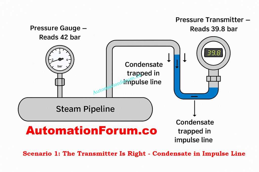
A pressure gauge and transmitter are both put on the same tap in a high-pressure steam condensate return line. The gauge says 42 bar, and the transmitter says 39.8 bar.
The transmitter looks strange at first. But when you use a digital pressure calibrator to verify both instruments, they are both completely in calibration.
Upon further examination, it is clear that the transmitter is connected via a long horizontal impulse line that holds condensate. The hydrostatic head from this column of liquid makes the transmitter read lower while it is working.
After draining and rerouting the impulse line with the right slope, both readings are now 39.8 bar.
Conclusion:
The transmitter was right; the wrong discrepancy was caused by a bad impulse line installation and too much condensate buildup, not by calibration drift.
Scenario 2: The Gauge Is Right – Ground Loop Affecting Transmitter
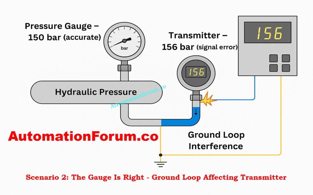
Operators discovered that the DCS measurement (from the transmitter) indicated 156 bar but the local gauge always showed 150 bar in a hydraulic test circuit that was working at about 150 bar.
Calibration checks showed that both instruments were correct, but the difference still existed. The investigation found that the signal was not properly grounded at two spots, which caused a ground loop that caused a voltage offset in the 4-20 mA loop.
The DCS value steadied at 150 bar, which matched the gauge, when the grounding was fixed to a single-point shield termination.
Conclusion:
The gauge was right, and the transmitter output error was caused by electrical noise and double grounding, not sensor imperfection.
Key Takeaways from These Advanced Scenarios
- Not all differences are caused by calibration drift; installation design, dynamic process behavior, and electrical integrity are also important factors.
- A transmitter may seem wrong during process upsets, but it could be showing true transient situations that a mechanical gauge can’t pick up.
- On the other hand, a transmitter can give false information if there are problems with the signal conditioning or grounding that change the measurement, even if the sensor itself is correct.
- To do a true root-cause analysis, you need to know how to troubleshoot both mechanical and electrical problems, as well as how process dynamics affect instrumentation.
Refer the below link for the Top Factors Affecting Pressure Transmitter Accuracy – What Every Engineer Should Know
Maintenance and Troubleshooting Checklist
If there is a difference between a pressure gauge and a transmitter, follow this list:
Check the calibration against a standard you can trust.
Check the height and direction of the installation
Look for obstructions, leaks, or trapped air in the impulse lines.
Check the gauge for evidence of overpressure or vibration damage.
Check the schedule for calibrating the transmitter and its drift history.
Check measurements at more than one pressure point
This methodical technique stops people from making assumptions and makes sure the data is accurate.
Step-by-Step Pressure Gauge Calibration Guide with Industry Standards: Pressure Gauge Calibration – Step-by-Step Procedure and Standards
Why Pressure Reading Accuracy Important
Some people could say that a slight variance in readings is not important. But in a lot of cases, accuracy is important for safety, quality, and efficiency.
- Safety: If the measurements in boilers, reactors, or pipes are wrong, there is a risk of overpressure.
- Process Control: If the transmitter readings are wrong, the DCS/PLC may not work as well as it should.
- Compliance: Many industries, like oil and gas, pharmaceuticals, and food processing, have severe calibration rules that they have to follow.
If not taken care of, even a “simple” pressure gauge might be a weak link.
Pressure Gauge Failure? Causes, Solutions & Troubleshooting Explained: Pressure Gauge Failure: Causes, Solutions & Troubleshooting Guide
Best Practices for Reliable Pressure Measurement
To keep readings accurate and prevent arguments:
- Regular Calibration: According to ISO/IEC 17025 or plant-specific requirements, both gauges and transmitters should be calibrated on a regular basis.
- Use dampeners or snubbers to keep gauges safe from vibration and pulsation.
- Install Pressure Transmitters the Right Way: Don’t put them in low spots where condensate might build up, and make sure they vent properly.
- Standardize Reference Devices: Always keep a high-accuracy digital calibrator available for troubleshooting.
- Maintain Records: For audits and future reference, write down the findings of calibrations, any deviations, and any remedial actions taken.
Pressure Transmitter Installation: Step-by-Step Guide for Accurate Setup: Step by Step Pressure Transmitter Installation Procedure
Future Trends – Digital Gauges and Smart Transmitters
Technology is closing the distance between gauges and transmitters.
- Digital pressure gauges now provide better accuracy, built-in data logging, and the ability to send data wirelessly.
- Smart Transmitters have diagnostics, prompts for self-calibration, and the ability to be monitored from afar using IIoT platforms.
In the near future, there may be less differences between instruments as they become self-verifying. But for now, engineers still have to use systematic troubleshooting.
It can be disturbing as well as hazardous to leave things alone when a pressure gauge and transmitter show contradictory readings. But if you take your time and test against a reference, verify the installation, look at the impulse lines, and think about how accurate the instrument is, you may be sure of which measurement to believe.
It’s not safe to guess when it comes to measuring pressure. You can only trust something if you check it, calibrate it, and use good technical judgment. This is true for a boiler, a chemical reactor, or even just a basic conduit.
The correct answer is not “gauge versus transmitter”; it is the one that matches the reference standard.