- What is an Absolute Pressure Transmitter?
- Applications of Absolute Pressure Transmitters
- Purpose and Scope
- Tools and Equipment Required
- Safety Precautions
- Step-by-Step Calibration Procedure for Absolute Pressure Transmitter
- Step 1: Preparation
- Step 2: Setup for Absolute Pressure Transmitter Calibration
- How do you calibrate absolute pressure?
- Step 3: Establish Zero Reference Pressure
- Step 4: Apply Full-Scale Pressure
- Step 5: Linearity and Accuracy Check
- Example Calibration Chart of Absolute Pressure Transmitter
- Step 6: Document Calibration Results
- Step 7: Completion of calibration
- Sample Calibration Report
- Standards for Calibrating Absolute Pressure Transmitters
- FAQs on Absolute Pressure Transmitter Calibration
- What is the range of an absolute pressure transmitter?
- What is the formula for absolute pressure?
- Why do we use an absolute pressure transmitter?
- What are the advantages of an absolute pressure transmitter?
- What is the difference between gauge and absolute pressure transmitters?
- Why is calibration important for absolute pressure transmitters?
What is an Absolute Pressure Transmitter?
An absolute pressure transmitter is an instrument that determines the total pressure exerted by a fluid (gas or liquid) in relation to a perfect vacuum. Absolute pressure transmitters are crucial for applications requiring accurate and reliable measurements because, in contrast to conventional pressure transmitters, they are not impacted by changes in atmospheric pressure.
Applications of Absolute Pressure Transmitters
- Industrial Process Control is used to monitor and maintain pressure levels in key operations.
- Vacuum monitoring is essential in vacuum systems such as distillation, freeze-drying, and semiconductor fabrication.
- Altitude testing involves simulating various atmospheric pressures in controlled situations, such as altitude chambers.
- Packaging Industry: Pressure monitoring for vacuum-sealed items.
Purpose and Scope
An absolute pressure transmitter’s accuracy is maintained over time through calibration, which aligns its readings with established reference pressures. Whether you are in a workshop or out in the field, this detailed guidance will walk you through the process of calibrating the transmitter.
Tools and Equipment Required
- Pressure Calibrator with digital Indication: A device to generate and measure pressure.
- Vacuum Pump: For creating a reference vacuum (0 PSIA / 14.7 psi).
- 24V DC Power Supply: To energize the transmitter.
- HART Communicator: For programming and configuring smart transmitters.
- Test Leads and Probes: To connect the transmitter to test equipment.
- Tubes and Fittings: Ensure they match the transmitter’s connections.
- Soft Cloth: For cleaning connections and equipment.
Safety Precautions
- For detailed safety guidelines, general recommendations, and calibration procedures in process industries, refer to the provided link:
Basic Safety and General Considerations for Process Industries Calibration Process
- Lockout/tagout procedures must always be carefully followed so that the transmitter is safely isolated from the process. This prevents inadvertent energization or the release of hazardous energy.
- Work areas should always be kept clean and organized in an orderly manner.
- Use proper ventilation so that hazardous gases do not accumulate within the workspace.
- Make sure that all non-essential equipment or tools that can be tripped over are removed from the location.
- Before starting the calibration work, the system needs to be depressurized completely.
- Isolate the section of the system that the transmitter is placed in so that no process fluids or gases reach the working area.
- Ensure proper working permits are obtained prior to the commencement of any calibration action.
- Comprehensively conduct a risk assessment, identify possible hazards, and take the proper control measures.
- If it is needed to bypass process interlocks, make sure that it is carried out with regard to the safety measures in place.
- Ensure the procedure for bypassing is documented and communicated to all offline personnel in order to provide the necessary process safety.
Step-by-Step Calibration Procedure for Absolute Pressure Transmitter
Step 1: Preparation
- Put together all the necessary tools and calibration instruments.
- Check the transmitter specifications: range and model number.
- Remove the transmitter from the process by closing the isolation valve or manifold.
- Relieve the pressure in the system by opening bleed or vent valves.
Step 2: Setup for Absolute Pressure Transmitter Calibration
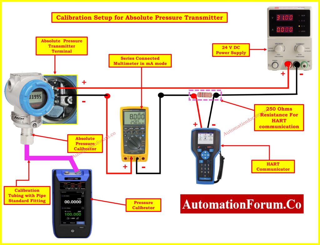
- Securely attach the transmitter on the testing bench.
- Establish a connection from the vacuum pump or pressure calibrator to the pressure port on the transmitter.
- Utilize a 24V DC power source to load the transmitter.
- Using a multimeter or calibrator, connect in series mode to the output (4-20 mA) of the transmitter.
- Connect HART communicator with 250 ohms for the smart transmitters to troubleshoot settings and parameters.
Click here for Wiring Diagram for Pressure Transmitter Calibration in Workbench using HART
How do you calibrate absolute pressure?
Step 3: Establish Zero Reference Pressure
- You can simulate the reference pressure by using the vacuum pump to produce a vacuum. This pressure is equal to 0 PSIA(-14.7psi).
Note: Creating a full vacuum is practically challenging and requires specialized equipment. Any residual pressure should be accounted for in calibration.
- The pressure should be monitored until it reaches a stable state at 0 Torr or the corresponding reference pressure.
- Check that the transmitter is capable of producing 4.000mA at this pressure.
- For any necessary adjustments to be made to the lower range value (LRV), the HART communicator or adjustment controls should be utilized.
Additional Note: At 0 pressure applied to the absolute pressure transmitter, it should display 14.7 psi or 1.02 kg/cm² (open to atmospheric pressure).
Step 4: Apply Full-Scale Pressure
- The highest range value (URV) of the transmitter’s measurement range, such as 2 kg/cm2, can be simulated using the pressure generator.
- Make sure the transmitter output reads 20.000 mA at this pressure by checking it.
- If there are differences, use the adjustment controls or the HART communicator to change the span.
Step 5: Linearity and Accuracy Check
- Throughout the calibration range, apply pressure in 25% increments (0%, 25%, 50%, 75%, 100%). For example 0- 2 kg/cm² transmitter range.
- At 0.5 kg/cm², the output should be 8 mA.
- At 1.02 kg/cm² (50%), the output should be 12 mA.
- At 1.5 kg/cm² (75%), the output should be 16 mA.
- At 2 kg/cm² (100%), the output should be 20 mA.
- To make sure it is repeatable, do the same check in reverse, from 100% to 0%.
- Verify that every reading falls within the tolerance given by the manufacturer.
Refer the below link for the Collection of Instrument Calibration Activity Calculators for Accurate Adjustments
Example Calibration Chart of Absolute Pressure Transmitter
| Range in Percentage (%) | Gauge Pressure (kg/cm²) | Absolute Pressure (kg/cm²) | Output (mA) |
| 0% | -1 kg/cm² | 0 kg/cm² | 4 mA |
| 25% | -0.5 kg/cm² | 0.5 kg/cm² | 8 mA |
| 50% | 0 kg/cm² | 1.02 kg/cm² | 12 mA |
| 75% | 0.5 kg/cm² | 1.5 kg/cm² | 16 mA |
| 100% | 1 kg/cm² | 2 kg/cm² | 20 mA |
| 75% | 0.5 kg/cm² | 1.5 kg/cm² | 16 mA |
| 50% | 0 kg/cm² | 1.02 kg/cm² | 12 mA |
| 25% | -0.5 kg/cm² | 0.5 kg/cm² | 8 mA |
| 0% | -1 kg/cm² | 0 kg/cm² | 4 mA |
Step 6: Document Calibration Results
- Record “as-found” and “as-left” readings in a calibration report.
- Note any deviations and corrective actions taken.
- Print or save the report for future reference.
Step 7: Completion of calibration
- Release the applied pressure and close the bleed valve.
- Disconnect all calibration equipment.
- Clean and inspect the transmitter for any visible damage.
- Reinstall the transmitter in its original location and reconnect to the process.
- De-isolate the system and open isolation valves and resume normal operations.
- Verify the transmitter’s functionality under process conditions.
- Normalise the bypassed signals from the transmitter
- Close Workpermit
Sample Calibration Report

This report documents the calibration of an Absolute Pressure Transmitter to ensure its accuracy and compliance with operational standards with following minimum example data.
- Transmitter Model: Absolute Pressure Transmitter FKA
Serial Number: 12345XYZ
Calibration Range: 0-760 Torr
Calibration Equipment: Digital Calibrator, HART Communicator - Special Note: Initial output readings were recorded as 4.002 mA for the lower range value (LRV) and 20.050 mA for the upper range value (URV). Post-adjustment, the output was corrected to 4.000 mA (LRV) and 20.000 mA (URV). The output deviation was within ±0.05% of the calibrated range.
- During the calibration process, no physical damage or abnormal wear was observed on the transmitter. The device is functioning within acceptable parameters after adjustment.
- Calibrated by: [Technician Name]
Date of Calibration: [DD/MM/YYYY]
Signature:
This report should be retained for compliance and audit purposes. Any future deviations or issues should be addressed promptly to ensure continued reliability.
The Excel template used for creating the absolute Pressure Transmitter calibration report is available for download via the link provided below for your convenience.
Click here for Downloadable Instrumentation Calibration Report Preparation Templates
Standards for Calibrating Absolute Pressure Transmitters
Calibration of absolute pressure transmitters follows recognized standards to ensure accuracy and reliability. Common guidelines include ISO 17025, which ensures calibration is traceable to international measurement standards, and ISA Standards, which provide recommendations for calibration procedures and accuracy checks. Additionally, many manufacturers and industries refer to NIST (National Institute of Standards and Technology) traceability to ensure calibration meets precise measurement requirements.
Click here for more Instrument Calibration Procedures
FAQs on Absolute Pressure Transmitter Calibration
What is the range of an absolute pressure transmitter?
Absolute pressure transmitters typically measure pressure starting from absolute zero, which is a perfect vacuum (0 psi or 0 Pa). This means they cannot measure negative values because absolute pressure cannot be less than zero. Depending on the transmitter model and application, the range can vary from near 0 psi (vacuum) to very high values, such as several thousand psi (e.g., up to 10,000 psi). Always consult the manufacturer’s specifications to determine the specific range for a particular model.
Click here Pressure Transmitter Commissioning Checklist
What is the formula for absolute pressure?
The absolute pressure is the total pressure in a system, which includes both the gauge pressure and atmospheric pressure. The formula is:
Pabs=Pg+Patm?
Where:
- Pabs?: Absolute pressure
- Pg?: Gauge pressure
- Patm?: Atmospheric pressure
Why do we use an absolute pressure transmitter?
Absolute pressure transmitters are used to measure pressure referenced against a perfect vacuum. They are ideal in applications where variations in atmospheric pressure could affect accuracy. Since these transmitters are independent of barometric pressure changes, they deliver reliable and precise measurements.
What are the advantages of an absolute pressure transmitter?
- Accuracy: Absolute pressure transmitters are unaffected by barometric pressure changes, making them more accurate than gauge pressure transmitters for most applications.
- High Repeatability: They provide consistent performance over repeated measurements.
- Long-Term Stability: Absolute pressure transmitters maintain stable output over long periods, reducing the need for frequent recalibration.
What is the difference between gauge and absolute pressure transmitters?
- Absolute Pressure Transmitters: These are referenced against a perfect vacuum (0 psi). They measure the total pressure in a system, including the atmospheric pressure.
- Gauge Pressure Transmitters: These measure pressure relative to ambient atmospheric pressure, which is approximately 1 bar (100 kPa) at sea level. Gauge pressure readings can fluctuate with changes in barometric pressure.
Why is calibration important for absolute pressure transmitters?
Calibration ensures that the transmitter provides accurate and reliable measurements over its operating range. Regular calibration is essential to account for any drift in the sensor, environmental factors, or process conditions.
Calibration typically involves:
- Comparing the transmitter output against a standard reference.
- Adjusting the transmitter to eliminate any deviation.
- Verifying accuracy at multiple points across the range.
Accurate calibration helps maintain process control, ensures safety, and improves overall system efficiency.