- Section No.1: Pre-Installation Planning
- Section No.2: Mounting the Transmitter
- Section No.3: Impulse Piping Installation
- Section No.4: Manifold Installation
- Section No.5: Electrical Wiring and Connections
- Section No.6: Canopy Installation
- Section No.7: Post-Installation Checks
- Section No.8: Documentation and Record Keeping
- Section No.9: Training and Handover
- Installing pressure transmitters is an important part of an Engineering, Procurement, and Construction (EPC) project that has a direct impact on the dependability and efficiency of industrial systems.
- This procedure represented the systematic process for installing pressure transmitters in adherence to industry standards and best practices, ensuring precise process measurements and system efficiency.
How to Install Pressure Transmitters?
Section No.1: Pre-Installation Planning
Before initiating the installation process, thorough pre-installation checks must be conducted to ensure a smooth and successful installation. These checks include:
Project Scope Review:
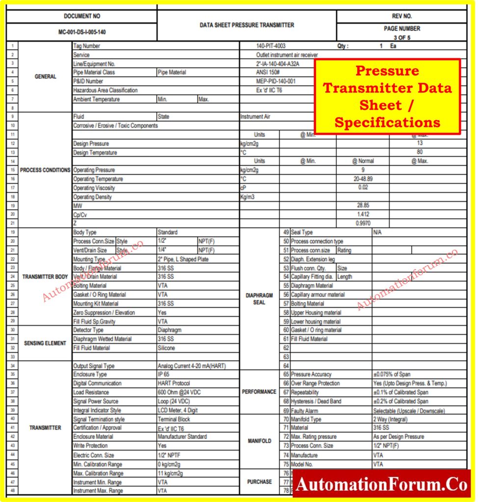
- Conduct a comprehensive review of the engineering deliverables, including Piping & Instrumentation Diagram (P&ID), Instrument Index, Instrument Data Sheet /Specification, and project requirements pertaining to pressure transmitter installation.
Site Assessment:
- Undertake a meticulous site assessment to determine optimal mounting locations for pressure transmitters, considering accessibility, process conditions, and safety regulations as specified in the engineering deliverables.
Material and Equipment Procurement:
- Procure all requisite materials, equipment, and tools necessary for pressure transmitter installation, ensuring alignment with the specifications outlined in the engineering deliverables.
- Ensure that all necessary equipment, including the pressure transmitter, impulse piping, mounting hardware, cables, and tools, are available and in good condition.
- Gather all necessary tools and equipment, including loop checking devices, multimeters, loop calibrators, and documentation such as loop diagrams and instrument datasheets.
Engineering Design Review:
- Scrutinize the engineering deliverables to ensure alignment with the installation requirements and confirm that the proposed mounting locations and impulse piping routing are in accordance with the design specifications.
- Refer to the manufacturer’s specifications and installation guidelines to understand the requirements and recommendations for the specific pressure transmitter model being installed.
Health, Safety, and Environment (HSE) Planning:
- Develop a comprehensive HSE plan specific to pressure transmitter installation, integrating the guidelines outlined in the engineering deliverables and addressing potential hazards, safety protocols, and emergency procedures.
- Isolate the pressure transmitter loop from the control system to prevent any interference or accidental activation during the pressure transmitter installation process.
Section No.2: Mounting the Transmitter
Proper mounting of the pressure transmitter is essential to ensure stability, accuracy, and longevity. Follow these steps for mounting:
Location Selection:
- Referencing the engineering deliverables(Instrument Location Layout), select suitable mounting locations for pressure transmitters that comply with the design specifications and ensure optimal performance and accessibility.
- Choose a location that provides easy access for maintenance, is free from excessive vibration, and is within the specified temperature and pressure limits.
Structural Support:
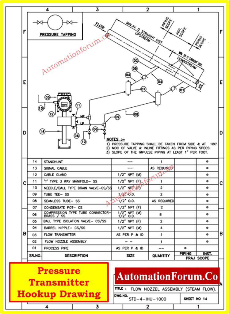
- Install robust structural support systems, including brackets, supports, or mounting hardware, as per the engineering drawings(Instrument Hook-Up Diagrams) to provide stability and withstand environmental factors and vibrations.
- Ensure the transmitter is securely mounted using appropriate brackets, supports, or mounting hardware. Avoid mounting directly onto vibrating equipment or surfaces.
Alignment Verification:
- Verify the alignment of mounting surfaces in accordance with the engineering drawings to ensure level and obstruction-free surfaces conducive to accurate installation.
- Keep corrosive or hot process materials away from the transmitter to prevent damage. Use protective barriers or insulation if necessary.
Section No.3: Impulse Piping Installation
The impulse piping connects the process to the transmitter and plays a critical role in accurate pressure measurement. Follow these best practices for impulse piping installation:
Impulse Line Routing
- Implement the impulse piping routing plan as delineated in the engineering deliverables(Instrument Hook-Up Diagrams), minimizing bends, obstructions, and sources of interference to maintain the integrity of pressure measurement.
- Minimize the length of impulse piping to reduce pressure losses and improve response time.
- Ensure that both impulse lines are at the same temperature to prevent density variations and measurement errors.
Pipe Preparation
- Prepare the impulse piping in accordance with the engineering specifications, including cutting, deburring, and cleaning, to facilitate smooth flow and effective sealing.
- Limit the number of joints and bends in the impulse piping to minimize potential leak points and pressure losses.
- Use impulse piping with sufficient diameter to minimize friction effects and avoid blockages.
Sloping and Support
- Ensure the appropriate slope and support for liquid impulse piping, adhering to the slope requirements specified in the engineering deliverables and providing adequate support to prevent sagging or damage.
- Take measures to prevent sediment deposits in the impulse piping, which can obstruct flow and affect measurements.
- For liquid service, slope the impulse piping upward from the transmitter towards the process connection at a minimum slope of 8cm per meter or linch per foot to prevent gas pockets and ensure proper drainage.
Sealing and Connection:
- Employ suitable fittings, valves, and connectors to securely seal and connect the impulse piping to the process and pressure transmitter, following the guidelines outlined in the engineering drawings.
- If using a sealing fluid, fill both piping legs to the same level to maintain accurate measurements.
Purge Properly:
- When purging, connect the purge connection close to the process taps and purge through equal lengths of the same pipe size to avoid purging through the transmitter.
- Ensure all trapped gas is vented from liquid piping legs to prevent measurement inaccuracies.
Section No.4: Manifold Installation
In some installations, pressure transmitters may be connected to a manifold assembly to facilitate multiple pressure measurements from a single location. Follow these steps for manifold installation:
Manifold Selection:
- Select a suitable manifold configuration based on process requirements, fluid compatibility, and installation constraints.
- Ensure that the manifold design allows for proper venting, draining, and isolation of individual pressure ports.
- Refer to manufacturer specifications and industry standards for guidance on manifold selection and installation.
Click here for Key Considerations for Pressure Transmitter Manifold Selection
Manifold Mounting:
- Mount the manifold assembly securely to a stable surface or support structure, ensuring proper alignment with process piping and instrumentation.
- Use appropriate fasteners and mounting hardware to secure the manifold in place, considering factors such as vibration and thermal expansion.
- Verify that the manifold is positioned to allow for easy access to pressure ports and instrument connections.
Manifold Venting and Draining:
- Ensure that the manifold assembly includes provisions for venting and draining to prevent air pockets or fluid accumulation within the manifold.
- Install vent valves and drain ports at strategic locations to facilitate purging and maintenance activities.
- Verify that vent and drain connections are accessible and properly sealed to maintain system integrity.
Section No.5: Electrical Wiring and Connections
Proper wiring and electrical connections are crucial for the reliable operation of the pressure transmitter. Follow these guidelines:
Cable Selection
- Select cables based on the electrical requirements specified in the engineering deliverables, ensuring compatibility with voltage, current, temperature, and environmental conditions.
- Use cable glands or conduits to protect wiring from mechanical damage, moisture, and other environmental hazards.
Wiring Routing
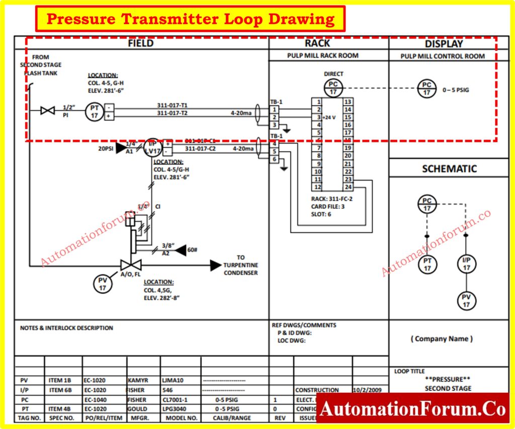
- Route electrical cables in accordance with the engineering drawings (Instrument Cable Schedule and Instrument Junction Box (JB) Schedule), avoiding sharp bends and exposure to hazards such as heat, moisture, or chemicals.
Terminal Connections
- Make terminal connections as per the manufacturer’s specifications and engineering drawings(Instrument Logic Diagrams), ensuring tight and secure connections to prevent electrical faults or signal interference.
Follow Wiring Diagram:
- Refer to the manufacturer’s wiring diagram and instructions to ensure correct wiring connections.
- Verify the continuity of the loop wiring by connecting a loop checking device or multimeter at the transmitter terminals and the corresponding terminals at the control system. Ensure that there are no open circuits or wiring faults.
- Check the polarity of the loop by ensuring that the positive and negative terminals are correctly connected at both ends of the loop. Incorrect polarity can lead to inaccurate readings or malfunctioning of the pressure transmitter.
Ensure Grounding:
- Properly ground the transmitter and associated electrical components to prevent electrical interference and ensure safety.
Section No.6: Canopy Installation
In certain industrial environments, installing a canopy or protective housing over pressure transmitters can provide additional protection from environmental elements such as extreme weather conditions, corrosive atmospheres, or physical damage. Follow these steps for canopy installation:
Canopy Selection:
- Select a suitable canopy design based on environmental conditions, material compatibility, and accessibility requirements.
- Ensure that the canopy design allows for proper ventilation to prevent heat buildup and condensation within the enclosure.
Canopy Mounting:
- Install the canopy securely over the pressure transmitter, ensuring proper alignment and clearance for maintenance access.
- Use appropriate mounting hardware such as brackets or supports to secure the canopy to structural elements or mounting surfaces.
- Verify that the canopy does not obstruct access to the pressure transmitter or impede its functionality.
Sealing and Weatherproofing:
- Apply appropriate seals or gaskets to ensure a weatherproof enclosure, preventing water ingress and moisture accumulation.
- Verify that cable entry points are adequately sealed to maintain environmental integrity.Consider using corrosion-resistant materials or coatings for canopies installed in corrosive environments to enhance longevity.
Section No.7: Post-Installation Checks
After completing the installation, perform thorough post-installation checks to verify the integrity and functionality of the system:
Leak Testing:
- Conduct thorough leak testing on all impulse piping connections and seals using appropriate methods specified in the engineering deliverables to verify integrity and reliability.
Functional Testing:
- Perform functional tests on pressure transmitters to validate accurate pressure measurement and signal transmission, comparing readings against reference instruments and system requirements.
- Use a loop calibrator or signal generator to simulate various pressure values within the operating range of the pressure transmitter. Verify that the transmitter accurately measures and transmits the simulated signals.
- Monitor the response of the control system to the simulated pressure signals. Ensure that the control system reacts appropriately to changes in pressure readings, such as opening or closing of control valves or activation of alarms.
Click here for Method Statement for Loop Checking of Pressure Transmitter Loop
Calibration, Commissioning and Verification:
- Verify the calibration of pressure transmitters using calibrated reference instruments, adjusting settings if necessary to meet specified accuracy standards as outlined in the engineering deliverables.
- Calibrate the pressure transmitter according to the manufacturer’s recommendations and industry standards using calibrated reference instruments.
- Commission the system by integrating the pressure transmitter into the control system and verifying its performance under normal operating conditions.
Click here for 7 Steps Calibration Procedure for Pressure Transmitter
Section No.8: Documentation and Record Keeping
In engineering projects, meticulous documentation is crucial for transparency, traceability, and compliance. This section emphasizes the importance of documenting pressure transmitter installation, calibration, and as-built conditions in line with project requirements.
Installation Records:
- Maintain detailed records of pressure transmitter installation activities, including equipment specifications, installation drawings, test results, and any deviations or modifications made during installation, as per the documentation requirements specified in the engineering deliverables.
Calibration Certificates:
- Retain copies of calibration certificates and records of calibration procedures for pressure transmitters, documenting calibration dates, results, and adjustments made in alignment with the documentation standards outlined in the engineering deliverables.
Click here for Downloadable Instrumentation Calibration Report Preparation Templates
As-Built Documentation:
- Update engineering drawings, P&IDs, and equipment lists to reflect as-built conditions and changes implemented during pressure transmitter installation, ensuring accuracy for future reference and maintenance as per the as-built documentation requirements specified in the engineering deliverables.
Section No.9: Training and Handover
Training:
- Provide comprehensive training to relevant personnel involved in the operation and maintenance of the pressure transmitter system.
- This training should cover topics such as system operation, troubleshooting procedures, maintenance requirements, and safety protocols.
- Ensure that operators and maintenance staff are familiar with the pressure transmitter’s functionality, including calibration procedures and signal interpretation.
- Address any questions or concerns raised by the client and ensure that they are equipped to effectively manage and maintain the system post-handover.
Handover Documentation:
- Prepare handover documentation, including operation manuals, maintenance manuals, as-built drawings, calibration certificates, and any other relevant documentation.
- Ensure that all documents are organized, accessible, and provided to the client or relevant stakeholders during the handover process.
System Acceptance:
- Conduct a formal acceptance process to verify that the pressure transmitter system meets the specified requirements and performance criteria outlined in the project scope and engineering deliverables.
- This process may involve functional tests, performance evaluations, and client approval.
Ongoing Support:
- Offer ongoing support and assistance to the client following the handover of the pressure transmitter system.
- Establish channels for communication and provide access to technical resources or expertise to address any issues or inquiries that may arise during operation or maintenance.