- Why Proper Venting Is Critical in Liquid Service
- Step-by-Step Procedure for Venting a Pressure/DP Transmitter
- 1. Identify the Vent Points on the Transmitter
- 2. Isolate the Transmitter Safely Using the Manifold Valves
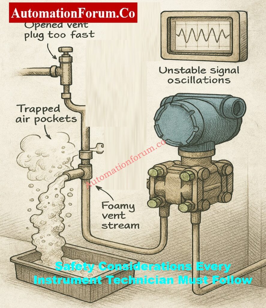
- 3. Control the Venting Carefully – Do Not Open the Vent Plug Too Quickly
- 4. Bleed the Transmitter Until a Consistent, Bubble-Free Stream Appears
- 5. Repeat the Venting Procedure for the Low-Pressure Side (Only for DP Transmitters)
- 6. Return the Transmitter to Service Using the Correct Valve Sequence
- Best Practices for Venting Transmitters in Real Plant Conditions
- Venting with Glycol-Filled (Sealing Liquid) Lines
- How to Confirm the Transmitter Has Been Properly Vented
- Safety Considerations for Instrument Technicians
- Importance of Proper Venting
- FAQ: Venting a Pressure Transmitter
To get accurate and steady pressure readings in liquid service, you need to do one thing that is often overlooked: venting the transmitter and impulse lines properly. Even a small pocket of trapped air can make the transmitter act in ways that are hard to predict, whether it is being used to measure level, flow, or pressure.
This in-depth article goes over why venting is important, how to do it right, and the best ways to do it in real industrial settings. It is made just for instrumentation engineers and technicians who operate in chemical plants, refineries, power stations, pharmaceutical units, and water treatment plants.
Why Proper Venting Is Critical in Liquid Service
When measuring liquids using a pressure or differential pressure transmitter, the sensor cavity and impulse lines must always be full with liquid. Any air or gas that is trapped will make the reading less accurate because:
Air is Compressible – Liquid is Not
Errors like these happen when air pockets get trapped:
- The transmitter took longer to respond because the gas was compressible and could alter pressure.
- Readings that are erratic or unstable and jump when the load changes
- Wrong values for differential pressure, notably in DP transmitters
- Drift in measurement or a movement to zero
- In DP level applications, levels that are too high or too low are wrong.
- In orifice, venturi, or pitot tube systems, flow measurements are not trustworthy. Also, it is not possible to get consistent calibration findings.
- Noisy feedback signals cause poor tuning and unstable control loops.
venting is one small act that has a direct effect on the health and accuracy of the whole measurement loop.
Gauge vs Transmitter – Accuracy Explained: Pressure Gauge vs Pressure Transmitter: When Readings Don’t Match, Who Should You Trust?
Step-by-Step Procedure for Venting a Pressure/DP Transmitter
This method works with practically all manufacturers and models of transmitters, such as Emerson, Yokogawa, ABB, Honeywell, Endress+Hauser, Siemens, WIKA, and VEGA.
1. Identify the Vent Points on the Transmitter
Before you do anything else:
- Find the vent screws or plugs that are only for the transmitter..
- Most transmitters have vent ports on:
- The high-pressure (HP) side
- The low-pressure (LP) side
- The top of the sensor housing
- Vent location varies depending on:
- Transmitter orientation
- Installation height
- Manifold type (3-valve or 5-valve)
- Impulse line routing
- For DP transmitters:
- To get the right differential measurement, both the HP and LP sides need to be vented.
Extended caution:
- Vent screws can be small and fragile, so be careful when you handle them so you don’t damage the threads.
- Some transmitters contain vent valves instead of plugs. These are meant to make venting safer while the transmitter is running.
Refer the beloe link for the DP Transmitter Boiler Drum Commissioning Guide: Commissioning Procedure for Differential Pressure Transmitters in Pressurized Boiler Steam Drums
2. Isolate the Transmitter Safely Using the Manifold Valves
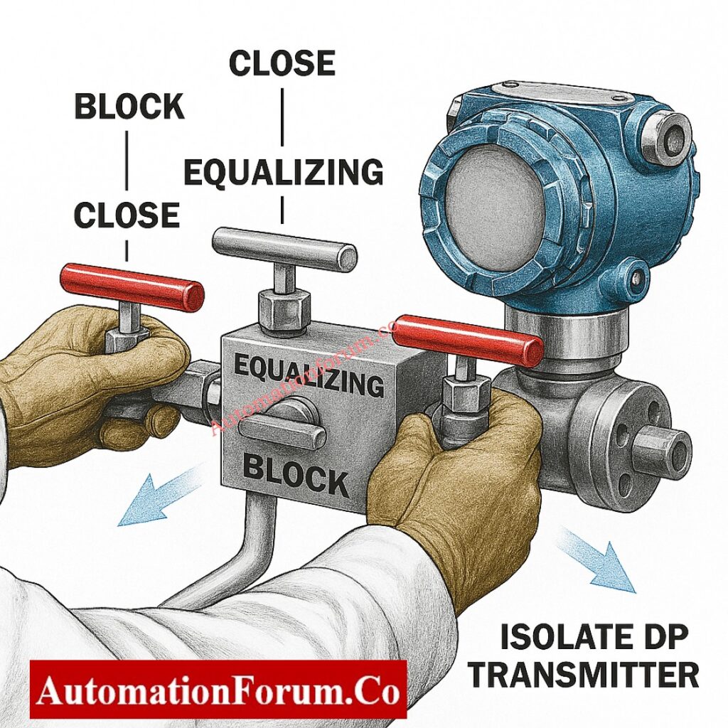
Safe venting is only possible with proper isolation. Do these things:
- To separate the transmitter from the process line, close both block valves on the manifold.
- During the first isolation, keep the equalizing valve completely shut.
- Check to make sure that isolation doesn’t influence control loops or interlocks.
- Tell the control room if the transmitter is part of a safety system or a critical loop.
- Make sure the line is safe and not under too much pressure or heat.
precautions:
- Residual pressure may still be trapped inside the transmitter cavity even after shutting the block valves.
- Until the instrument is fully vented, treat it as if it is pressured.
Refer the below link for How to Safely Zero a DP Transmitter with 3-Way Valve and 5-Way Valve Manifolds
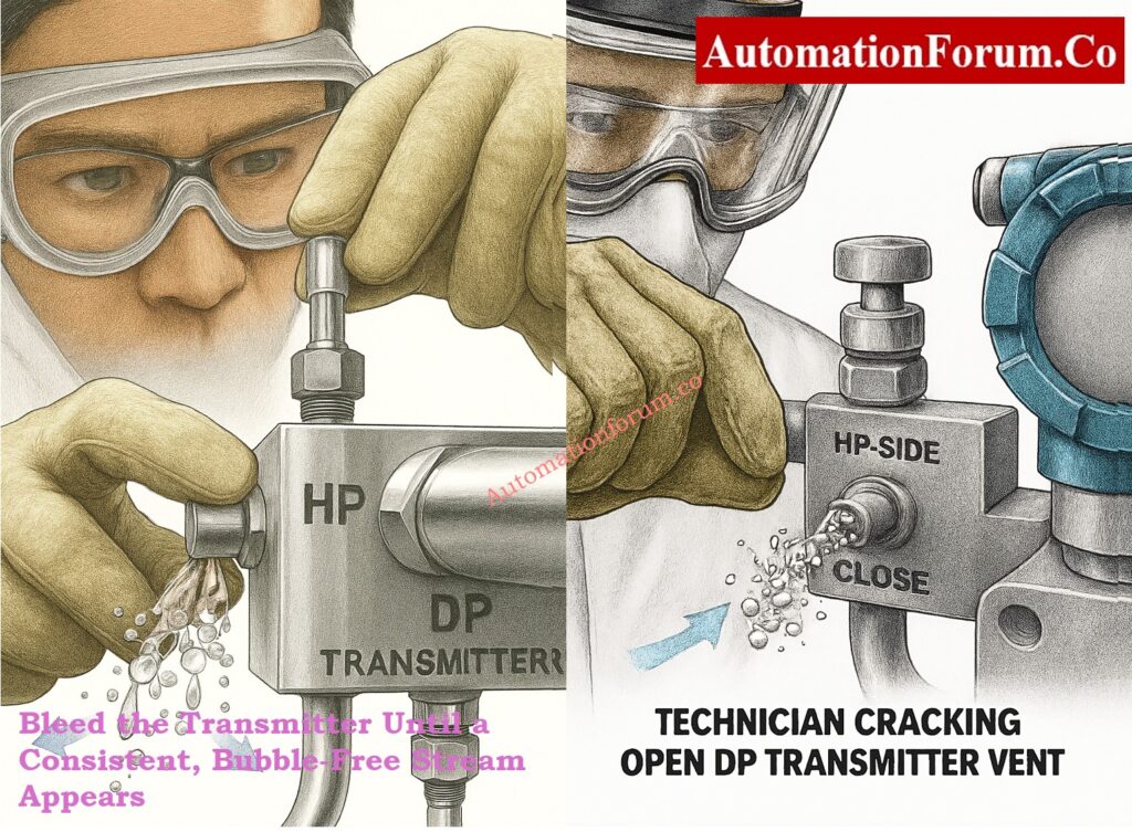
3. Control the Venting Carefully – Do Not Open the Vent Plug Too Quickly
Once the transmitter is separate:
- put a clean rag, absorbent cloth, or small container beneath the vent point to capture any liquid that comes out.
- Loosen the HP-side vent plug a little at a time.
- Slowly loosen the HP-side vent plug.
- Only crack open the plug slightly – do not remove it completely.
- Watch for Sudden blasts of air, Discharge of foam or mixed air and liquid, Sputtering at first, then a constant flow
Extended best practices:
- If you open it too hastily, the pressurized liquid could suddenly come out.
- Don’t put your body or face right in front of the vent point.
- Wear the right PPE, like gloves, an apron, goggles, and a face shield, when working with hot or corrosive fluids.
4. Bleed the Transmitter Until a Consistent, Bubble-Free Stream Appears
This is the most crucial element of letting air out:
- Allow the fluid to flow freely.
- Pay close attention to the discharge.
- You may initially see Air pockets mixed with liquid, Fluctuating or foamy flow, Irregular spurts indicating trapped gas
- Keep venting until the liquid flow is: Clear, Continuous, Bubble-free. Stable in pressure and flow rate
What this indicates:
- The detecting diaphragm chambers are full with liquid all the way through.
- There are no longer any air pockets trapped inside the housing.
- The accuracy of measurements will get a lot better.
notes:
- This procedure may take longer when working with thick liquids.
- In cold places, air may move liquid more slowly because the fluid is denser.
Gently but firmly tighten the vent plug when the flow is free of air bubbles.
DP Transmitter 3-Valve Manifold Safety Guide: Safe Commissioning & Removal of DP Transmitters with a 3-Way Valve Manifold
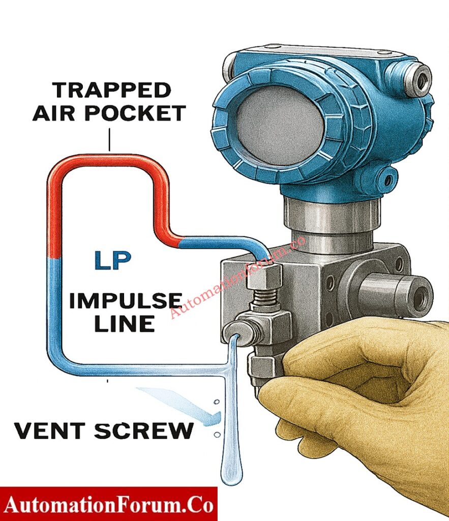
5. Repeat the Venting Procedure for the Low-Pressure Side (Only for DP Transmitters)
For differential pressure applications:
- do the same slow venting technique on the LP side.
- The LP side often traps air more often because it is normally higher up. It may have longer impulse tubing, Air naturally rises into the LP leg during shutdown
Extended effects of not venting the LP side:
- Incorrect differential pressure readings
- Zero point errors
- False level or flow calculations
- Drift is caused by an imbalance between the HP and LP legs.
Making ensuring that both sides are adequately vented brings back the right way to detect differential pressure.
Pressure Transmitter Installation – Step-by-Step: Step by Step Pressure Transmitter Installation Procedure
6. Return the Transmitter to Service Using the Correct Valve Sequence
A common mistake in the field is rapidly applying pressure to the transmitter after venting. This must be avoided.
Follow this recommended sequence:
- First, open the equalizing valve so that the transmitter sees zero DP.
- Then, carefully open both block valves to let process pressure in.
- Finally, close the equalizing valve to get the DP measurement back to normal.
Why this matters:
- Stops abrupt pressure shocks that can hurt diaphragms
- Keeps sensing membranes from getting stressed out inside
- Ensures zero stability
- Lessens the chance of having trapped pressure pockets inside. changing
Reminders:
- After putting the transmitter back into action, check the live signal from the control system or handheld device to make sure the readings are reliable.
DP Transmitter 5-Valve Manifold Installation Guide: Step-by-Step Guide: Installing & Removing a DP Transmitter with a 5-Way Valve Manifold
Best Practices for Venting Transmitters in Real Plant Conditions
Instrumentation engineers typically have problems that come up in the field. These basic practices make sure that the venting procedure is clean and complete:
Venting Based on Transmitter Orientation
- For horizontal impulse lines, always vent at the highest point where air gathers.
- For vertical impulse lines, let air out at the top of the transmitter body.
- For vessels with top-mounted transmitters, look for vapor pockets accumulating below the tapping points.
Handling Special Fluids
- For thick liquids, vent slowly so that the fluid has time to push the air out.
- For fluids that are corrosive or poisonous, wear the right PPE and take the right steps to clean up spills.
- For hot liquids, step back and very carefully manage the opening.
Considering Impulse Line Layout
- Long impulse lines tend to gather air when they first start up.
- Repeated air trapping happens when impulse lines are poorly sloped or drooping.
- Level applications have fewer problems with air when you use vertical wet legs.
Pressure Transmitter Commissioning Checklist: Pressure Transmitter Commissioning Checklist
Venting with Glycol-Filled (Sealing Liquid) Lines
Never start venting at the transmitter if the impulse lines are full of sealing liquid like glycol. This will drain the liquid and mess up the wet-leg reference height. Always vent from the highest point in the impulse line or seal pot to get rid of trapped air without changing the glycol column. Before you touch the transmitter vents, make sure both legs are completely full and equal. When the wet legs are clear of bubbles, separate the transmitter and carefully vent just the sensor cavity. If you lose any glycol, fill both legs back up equally to avoid making permanent level errors.
Smart Transmitter Sensor Trim – Full Guide: Smart Pressure Transmitter Sensor Trim Guide with Diagrams & Calibration Steps
Common Problems Caused by Improper Venting
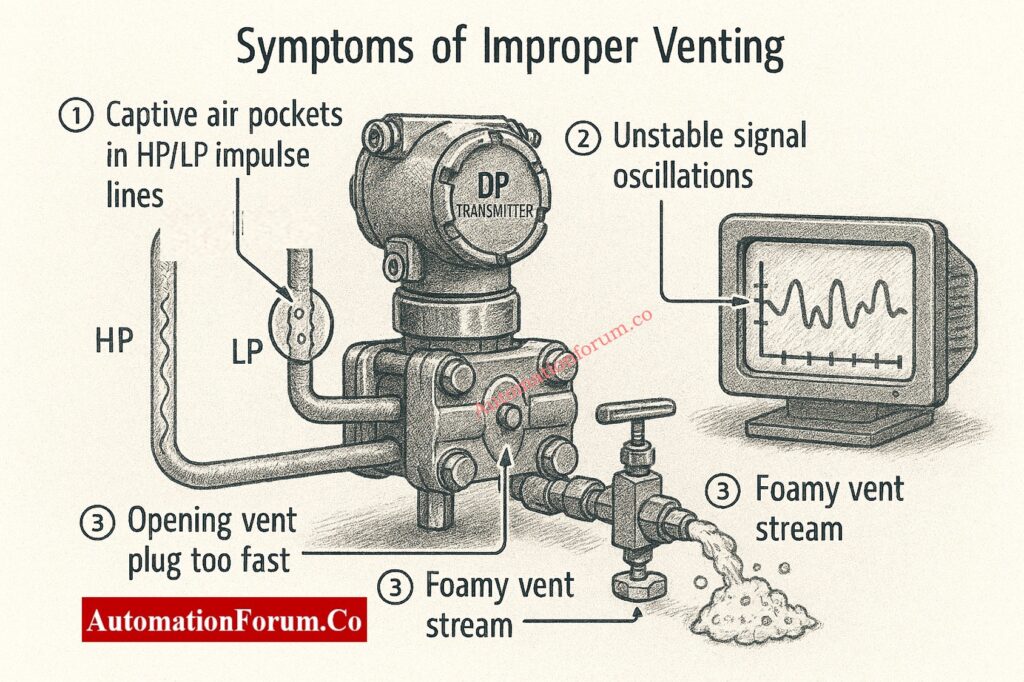
If the transmitter isn’t ventilated properly, you might see:
- Unstable or noisy readings
- Slow response or “spongy” behavior
- Wrong level measurement in DP systems
- Fluctuating flow measurements
- Zero shift during calibration
- Frequent alarms on DCS
- Inconsistent output even after calibration
Extended impact:
- Controllers may search since the measurements aren’t stable.
- Safety interlocks can go off by accident.
- Maintenance personnel could spend too much time fixing equipment that isn’t broken.
Pressure Transmitter Hookup Reading Made Easy: How to Read Pressure Transmitter Hookup Drawings ?
How to Confirm the Transmitter Has Been Properly Vented
You can check to see if the venting method works by:
- Output from the transmitter that is smooth and steady
- No rapid changes in reading or oscillations
- No strange delay in response
- Output accuracy checked against reference gauges
- Value of zero stays the same during equalization
- The last reading matches what was expected for the process.
Refer the below link for the Absolute Pressure Transmitter Calibration Steps
Safety Considerations for Instrument Technicians
Always prioritize safety:
- Put on the right PPE for the service fluid.
- Follow the steps for isolating plants.
- Drip trays can help keep spills and slips from happening.
- Don’t let your face or body get near the vent.
- To keep the threads safe, don’t over-tighten the vent plugs.
- Don’t ever think a transmitter is depressurized without checking first.
Importance of Proper Venting
For reliable, precise, and safe measurement in liquid service, pressure and differential pressure transmitters must be vented correctly. Instrumentation staff can do the following by following the right protocols for isolation, controlled venting, and returning to service:
- Get rid of air pockets
- Make the transmitter respond better
- Stop measurement drift
- Improve the performance of the whole loop
- Cut down on troubleshooting that isn’t needed
- Make plants more reliable
By mastering this easy but important chore, you can make sure that your transmitters work at their best, which will help you control your processes consistently and accurately.
DP Flow Transmitter Commissioning Checklist: Differential Pressure Transmitter Commissioning Checklist for Flow Measurement Applications
FAQ: Venting a Pressure Transmitter
How do you vent a pressure transmitter?
To vent a pressure transmitter that is in liquid service, use the manifold block valves to isolate it, put a container under the vent plug, and slowly open the vent screw. Let the fluid run until you see a clear stream with no bubbles. This gets rid of air pockets that can mess up measurements. After venting, carefully close the screw and put the transmitter back into use in the right order.
How to install a pressure transmitter if the service is liquid?
To maintain the transmitter fully flooded, put it below the tapping point, make sure the impulse lines slope down toward the transmitter, stay away from high locations where air can accumulate, and use the right block valves and a manifold. After putting it in, open the transmitter to allow out air and make sure the sensor chamber is full of liquid.
How to drain a pressure transmitter?
To drain a transmitter, use the manifold to separate it from the rest of the system. Then, open the drain or vent plug at the bottom of the housing and let the liquid flow out fully. Follow plant safety rules, use a catch container, and make sure the process is depressurized if necessary. Usually, draining is done before maintenance, calibration, or when the service circumstances change.
How to bleed a differential pressure transmitter?
To bleed a DP transmitter, you need to isolate it, put a container beneath the vent plugs, and progressively open the high-pressure vent first. This will let out all of the air and let a stream of liquid flow without bubbles. Do the same thing on the low-pressure side. Make sure that both sides are thoroughly vented before putting the transmitter back into service using the equalizing valve procedure.
How to zero trim a transmitter?
What are the 5 points of calibration?
A normal 5-point calibration has:
- 0% (As-Found) – Check the first zero.
- 25%-Use and record the output.
- 50%-Verification in the middle range.
- 75%-Check the near-upper range.
- 100% (As-Found) – Full-scale confirmation.
After making changes, go over the same five points for As-Left. This makes sure that the whole range of measurements is linear, accurate, and repeatable.
Pressure Transmitter HART Wiring Explained: Wiring Diagram for Pressure Transmitter Calibration in Workbench using HART