Instrument Cable Gland Selector Calculator
Engineering Inputs
Engineering Recommendations
Recommendations
Engineering Report
- What Is the Instrument Cable Gland Selector Calculator?
- Why Cable Gland Selection Is Important in Industrial Installations
- How the Instrument Cable Gland Selector Calculator Works
- Input Parameters Used by the Cable Gland Selector Calculator
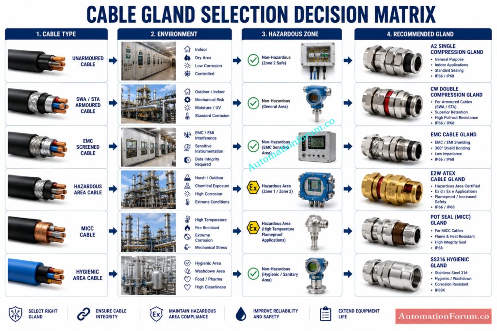
- Cable Construction Types Used in Gland Selection
- Environmental Conditions That Affect Cable Gland Choice
- Hazardous Area Cable Gland Selection
- Why Cable Outside Diameter Matters in Cable Gland Sizing
- Cable Gland Thread Size Selection Guide
- How to Select the Right Cable Gland Material
- Types of Cable Glands Recommended by the Calculator
- Understanding IP Ratings for Cable Glands
- Relevant Engineering Standards for Cable Gland Selection
- Practical Cable Gland Selection Examples
- Common Cable Gland Selection Mistakes to Avoid
- Troubleshooting Cable Gland Problems
- Best Practices for EPC, Commissioning, and Maintenance Engineers
- Cable Gland Selection Checklist
- Frequently Asked Questions About Cable Gland SelectionWhat is a cable gland used for?
- Conclusion: Improve Industrial Reliability with Proper Cable Gland Selection
How to Select the Right Cable Gland for Industrial Instrumentation and Electrical Installations
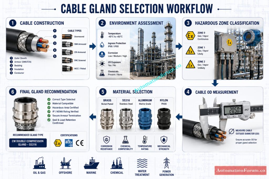
In industrial instrumentation and electrical installations, a cable gland is far more than a simple cable entry accessory. It is the final mechanical, environmental, and often safety-critical interface between a cable and an enclosure. A wrong gland choice can lead to water ingress, poor strain relief, corrosion, electromagnetic interference problems, sealing failure, and in hazardous locations, serious non-compliance risks. That is why engineers need a structured and reliable way to select the right gland every time.
The Instrument Cable Gland Selector Calculator helps simplify this process by matching the gland recommendation to cable construction, environmental conditions, hazardous area zone, cable outside diameter, and material requirement. The calculator is designed for real engineering use, not just theory, and it gives a best-match recommendation, a thread size suggestion, and an IP-oriented selection summary. The uploaded calculator currently works from cable construction, environment, zone, cable OD, and material, and it generates a recommendation such as CW double compression, EMC, E2W ATEX, MICC pot seal, or hygienic stainless steel based on those conditions.
For EPC, commissioning, maintenance, and project engineers, that kind of structured selection can save time, reduce mistakes, and improve long-term reliability.
Lock down gland termination quality with this checklist: Checklist for Cable Glanding & Termination
What Is the Instrument Cable Gland Selector Calculator?
The Instrument Cable Gland Selector Calculator is a practical engineering aid that helps users choose a suitable gland based on the conditions of the installation. It is especially useful where the wrong gland can compromise sealing, retention, or compliance.
The calculator in the uploaded file is built around five main engineering inputs:
- cable construction
- environment
- hazardous zone
- cable outside diameter
- gland material
It returns three key outputs:
- Best Match
- IP Rating
- Thread Size
The current logic also creates a short engineering report for documentation and checking. The file shows that the calculator is intended for “professional cable gland selection for EPC and instrumentation work,” and it displays compliance with IEC 62444, BS 6121, and IEC 60079.
Choose tray sizes that pass IEC and NEC tests: Cable Tray Sizing Calculator: Complete Engineering Guide for IEC 61537 and NEC 392 Compliance
Why Cable Gland Selection Is Important in Industrial Installations
In the field, cable glands are often selected too quickly, copied from previous jobs, or chosen only by thread size. That leads to mistakes. A good selection tool forces the engineer to think about the real service conditions, not just the enclosure hole size.
How the Instrument Cable Gland Selector Calculator Works

The calculator logic is deliberately simple, which is a strength. It does not try to replace engineering judgment. Instead, it narrows the options based on the most important selection factors.
Cable Construction Selection
The tool accepts these cable types:
- Unarmoured
- SWA
- STA
- EMC Screened
- MICC
Cable construction is the first decision because it determines whether the gland must grip armour, preserve screening continuity, or support mineral-insulated sealing.
Environment Selection
The environment choices are:
- General
- Outdoor
- Submersible
- Corrosive
- Hazardous
- Hygienic
This drives the need for sealing, corrosion resistance, material choice, and hazardous-area compliance.
Hazardous Area Zone Selection
The calculator includes:
- Safe Area
- Zone 2
- Zone 1
- Zone 0
- Zone 22
- Zone 21
That is important because the gland must suit the enclosure location and protection concept.
Refer the below link for the Master hazardous area gland selection before costly failures
Cable Outside Diameter Selection
Cable outside diameter is a core sizing parameter. A gland must seal the actual cable OD correctly; otherwise, the system may lose its ingress protection or retention performance.
Gland Material Selection
The material setting influences corrosion resistance, chemical compatibility, mechanical strength, and hygiene suitability.
Output
The calculator currently gives:
- best match
- IP rating
- thread size
- a short report
It uses a thread-size mapping of:
- up to 7 mm → M12
- up to 10 mm → M16
- up to 13 mm → M20
- up to 18 mm → M25
- up to 25 mm → M32
- up to 32 mm → M40
- above that → M50+
It also defaults the displayed IP rating to IP68 and changes the recommendation based on cable construction and environment. For example, SWA or STA gives a CW double compression gland, hazardous environment gives E2W ATEX, EMC screened cable gives EMC-A, MICC gives MCI pot seal, and hygienic service gives SS316 Hygienic.
Stop using wrong cables in Ex zones today: What Cables to Use in Ex Zones: Complete Guide for Instrumentation & Control Engineers
Input Parameters Used by the Cable Gland Selector Calculator
| Input Parameter | Engineering Significance | Industrial Application | Impact on Gland Selection |
| Cable construction | Determines armour, screen, or special sealing need | Instrument loops, power cables, analyzers, field devices | Decides whether single compression, double compression, EMC, or MICC gland is needed |
| Environment | Defines corrosion, moisture, washdown, or outdoor exposure | Offshore, wastewater, process plants, food plants | Drives material and IP requirement |
| Hazardous zone | Determines explosion protection needs | Zone 1, Zone 2, Zone 21, Zone 22 areas | Requires certified hazardous-area gland |
| Cable OD | Ensures proper clamping and sealing | All industrial cables | Sets thread size and sealing range |
| Material | Controls corrosion resistance and hygiene suitability | Chemical, marine, pharmaceutical, outdoor service | Chooses brass, nickel-plated brass, SS316, aluminium, or nylon |
Fix cable tray installation errors before they spread: Avoiding Mistakes in Instrumentation Cable Tray Installation: A Guide for EPC Projects
Cable Construction Types Used in Gland Selection
Unarmoured Cables
Unarmoured cables are common in control systems, light-duty instrumentation, and indoor installations. They are easier to terminate because there is no armour to bond or clamp. In many safe-area applications, a single compression gland is enough, provided the gland seals to the cable OD and the enclosure rating is suitable.
Typical uses include:
The main concern is sealing and retention, not armour termination. For these cables, the gland must grip the outer sheath properly and maintain the required IP rating.
Steel Wire Armoured (SWA) Cables
SWA cables are used where mechanical protection is needed. They are common in plant power distribution, outdoor routing, buried runs, and harsh industrial areas. SWA gland selection is different because the gland must do two jobs: seal the cable and terminate the armour correctly.
Typical uses include:
- motor feeders
- outdoor power circuits
- pumps and skids
- plant distribution wiring
For SWA, a CW double compression gland is often preferred because it supports armour retention and better sealing.
Steel Tape Armoured (STA) Cables
STA cables are less flexible than SWA and are often used where robust mechanical protection is needed in specific installations. The cable armour type influences the gland design and termination method. Incorrect gland selection can lead to poor retention or incomplete armour bonding.
Typical uses include:
- underground feeds
- harsh utility networks
- fixed industrial installations
STA often needs a gland type that can deal with the cable’s outer structure properly, especially where the armour layer must be securely terminated.
EMC Screened Cables
EMC screened cables are used in systems sensitive to electrical noise. These are extremely common in instrumentation loops, analyzers, VFD-adjacent circuits, communication lines, and precision measurement systems. The gland is important because the screen must be properly bonded to maintain electromagnetic shielding continuity.
Typical uses include:
- analyzer houses
- PLC and DCS signal wiring
- speed control systems
- instrument loops near power conductors
EMC glands are designed to preserve screen continuity and reduce interference.
Mineral Insulated Cables (MICC)
MICC cables are used where fire resistance, very high temperature resistance, and long-term integrity are required. They need special sealing and termination methods because the cable construction is entirely different from polymer-insulated cables.
Typical uses include:
- fire alarms
- emergency systems
- critical shutdown circuits
- high-temperature areas
MICC glands are usually pot-seal or dedicated termination types because the cable needs a specialised sealing arrangement.
Follow this proven instrumentation cable termination method: Method Statement for Instrumentation Cable Termination
Environmental Conditions That Affect Cable Gland Choice
General Industrial Areas
General indoor areas may not require the highest corrosion resistance, but they still need proper sealing and mechanical security. A well-sized brass or nickel-plated brass gland is often adequate.
Outdoor Installations
Outdoor glands face UV, rain, dust, condensation, and temperature cycling. The gland must handle weather exposure and maintain the enclosure’s IP performance.
Submersible Applications
Submersible service is one of the most demanding conditions. The gland must be selected with careful attention to sealing, cable diameter accuracy, and immersion suitability.
Corrosive Environments
Chemical plants, offshore platforms, wastewater plants, and coastal sites often need SS316 or similarly resistant materials. Corrosion resistance is not optional in these areas.
Hazardous Areas
The gland must comply with the hazardous area protection concept. That means the right certification, right sealing method, and right installation practice.
Hygienic and Food Grade Areas
In food, beverage, and pharmaceutical plants, the gland must be easy to clean, corrosion resistant, and suitable for washdown. Stainless steel is often preferred.
Build ATEX-safe cable choices with this checklist: Intrinsically Safe Cables for ATEX Zones – Complete Checklist for EPC Engineers
Hazardous Area Cable Gland Selection
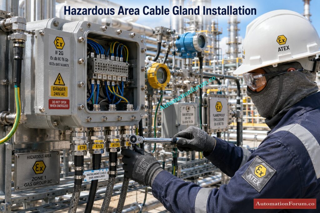
Hazardous area selection is not just about the gland body. It is about the full system: zone classification, cable type, enclosure, installation method, and compliance with the area protection standard.
Safe Area
A safe area does not require explosive atmosphere certification, but quality sealing and retention are still important.
Zone 2 Cable Gland Requirements
Zone 2 means an explosive atmosphere is not likely in normal operation and, if it occurs, it lasts only a short time. Cable glands must still be suitable for the equipment and enclosure.
Zone 1 Cable Gland Requirements
Zone 1 is higher risk. Equipment and accessories must be selected with stricter control and proper certification.
Zone 0 Cable Gland Requirements
Zone 0 is the highest gas-risk area, where explosive atmosphere is present continuously or for long periods. Selection and installation become highly restrictive.
Zone 22 Cable Gland Requirements
Zone 22 is a dust hazardous area with lower frequency and duration of explosive dust atmosphere.
Zone 21 Cable Gland Requirements
Zone 21 has a higher dust risk and requires stronger attention to sealing and certification.
The calculator’s hazardous-area selection of E2W ATEX reflects this kind of special requirement.
Eliminate cable management chaos with tray accessories: How to Fix Common Cable Management Issues using Cable Tray Accessories
Why Cable Outside Diameter Matters in Cable Gland Sizing
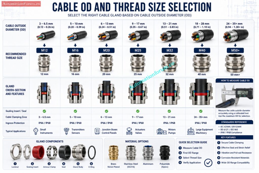
Cable outside diameter is one of the most important practical parameters in gland selection. If the gland is too large, the cable may not seal properly. If the gland is too small, installation may damage the sheath or prevent proper entry.
Why cable OD matters
- It determines whether the sealing insert can compress correctly.
- It affects strain relief and cable retention.
- It influences IP rating performance.
- It decides the correct thread size.
Consequences of incorrect sizing
- water ingress
- dust ingress
- cable pullout risk
- poor mechanical grip
- loss of IP protection
- accelerated seal wear
- eventual failure during service
A good cable gland should match the OD range closely enough to seal and clamp effectively without damaging the cable.
Calculate cable tray fill fast and accurately: Cable Tray Fill Percentage Calculator
Cable Gland Thread Size Selection Guide
The calculator uses a practical OD-to-thread logic:
- up to 7 mm → M12
- up to 10 mm → M16
- up to 13 mm → M20
- up to 18 mm → M25
- up to 25 mm → M32
- up to 32 mm → M40
- above that → M50+
Practical examples
A 6.5 mm instrument cable may suit M12.
A 9.5 mm control cable may suit M16.
A 14 mm SWA cable may move to M25 depending on gland family and clamping range.
A 22 mm industrial power cable may require M32 or M40 depending on the gland design.
The thread size should never be chosen only from the panel hole. It must align with cable OD, gland body, and enclosure entry requirement.
Catch wiring defects before startup with this procedure: Instrumentation Cable and Wiring Inspection Procedure: Essential checklist for Project Engineers
How to Select the Right Cable Gland Material
Brass Cable Glands
Brass is economical, strong, and suitable for many general industrial applications. It is common where corrosion exposure is moderate.
Nickel Plated Brass Cable Glands
Nickel plating enhances surface resistance and attractiveness, and provides superior resistance than plain brass in many conditions.
316 Stainless Steel Cable Glands
This is the best option for corrosive, offshore, maritime and hygienic applications. Corrosion resistance is strong and service life is lengthy.
Aluminium Cable Glands
It is light weight and can be beneficial in some industrial situations but not necessarily the best choice for highly corrosive or aggressive chemical environments.
Nylon Cable Glands
Good for mild duty and non-metallic requirements. Often seen in general enclosures and cost-sensitive applications, but not suitable for every industrial duty.
| Material | Corrosion Resistance | Mechanical Strength | Cost | Typical Application |
| Brass | Moderate | Good | Low | General industrial, indoor service |
| Nickel Plated Brass | Better than brass | Good | Moderate | Outdoor and mildly corrosive service |
| 316 Stainless Steel | Excellent | Very good | Higher | Offshore, chemical, hygienic, marine |
| Aluminium | Moderate | Good | Moderate | Lightweight industrial use |
| Nylon | Good in many non-aggressive areas | Lower | Low | Control panels, light-duty wiring |
Get a clean, complete instrument cable schedule template: Instrument Cable Schedule: Template, Example, Format and Complete Guide
Types of Cable Glands Recommended by the Calculator
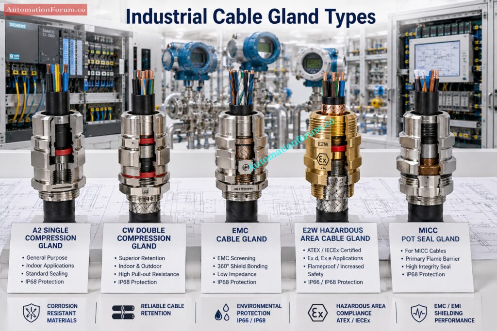
A2 Single Compression Cable Gland
A single compression gland seals the outer sheath and is commonly used for unarmoured cables in safe or general environments.
Advantages
- simple installation
- cost-effective
- suitable for many standard cables
Limitations
- not ideal for armoured terminations
- not intended for every harsh service condition
CW Double Compression Cable Gland
A CW double compression gland is widely used for SWA or STA cables because it grips the armour and seals the outer sheath.
Advantages
- excellent mechanical retention
- strong armour termination
- reliable for industrial power cables
Limitations
- more installation steps
- must be assembled correctly to achieve performance
EMC Cable Gland
EMC glands are used where screen continuity matters. They help maintain shielding and reduce interference.
Advantages
- better EMC performance
- suitable for signal integrity
- preferred for analyzers and control systems
Limitations
- screen termination must be done correctly
- can be misinstalled if field practice is poor
E2W Hazardous Area Cable Gland
This type is used when hazardous-area compliance matters. It is selected when the area classification and protection concept require a certified solution.
Advantages
- supports hazardous-area compliance
- suitable for stricter industrial duty
Limitations
- requires careful certification checking
- installation must follow the approved method
MICC Pot Seal Cable Gland
Used for mineral-insulated cables where termination and sealing are special.
Advantages
- suitable for fire-rated and high-temperature service
- specialized sealing capability
Limitations
- not interchangeable with standard glands
- requires special installation skill
316 Stainless Steel Hygienic Gland
Used where cleanability, corrosion resistance, and hygienic performance matter.
Advantages
- excellent corrosion resistance
- suitable for washdown and clean environments
Limitations
- higher cost
- may be unnecessary in simple indoor jobs
The calculator’s recommendation logic maps SWA/STA to CW double compression, hazardous service to E2W ATEX, EMC screened cable to EMC-A, MICC to MCI pot seal, and hygienic service to SS316 Hygienic.
Understand shielding mistakes that wreck signal performance: What is instrument cable shielding?
Understanding IP Ratings for Cable Glands
| IP Rating | Protection Summary | Practical Meaning in Industrial Use | Typical Applications |
| IP54 | Limited dust ingress protection and protection against water splashes | Suitable for basic indoor or light-duty installations where the environment is not harsh | Indoor panels, protected junction boxes, control rooms |
| IP65 | Dust tight and protected against low-pressure water jets | Good for outdoor and general industrial use where rain, dust, and washdown are possible | Field enclosures, outdoor instruments, process skids |
| IP66 | Dust tight and protected against powerful water jets | Better choice for more severe outdoor exposure and frequent washdown conditions | Refinery areas, wastewater plants, outdoor analyzer panels |
| IP67 | Dust tight and suitable for temporary immersion | Used where short-term water immersion may occur | Low-level outdoor equipment, pit installations, occasional flooding exposure |
| IP68 | Dust tight and suitable for continuous immersion under specified conditions | Highest level among these options, but only valid under the stated manufacturer conditions | Submersible devices, underground or immersed installations |
| Engineering Note | Explanation |
| Ingress protection importance | The gland helps the enclosure resist dust and water entry, which protects the electrical or instrumentation system from premature failure |
| Selection approach | IP rating should match the actual environment, not just be chosen as the highest available rating |
| Common use cases | Instrument panels, field junction boxes, analyzers, and outdoor devices all need the IP rating to suit the cabinet design and site conditions |
Find the real causes behind most industry failures: What Causes 80% of Instrument Failures in Industry? Top 10 Causes and Prevention Methods
Relevant Engineering Standards for Cable Gland Selection
| Standard | What It Covers | Why It Matters for Cable Gland Selection | Practical Impact |
| IEC 62444 | Requirements and test methods for cable glands, including classification, sealing performance, cable retention, environmental resistance, and documentation | It is central to proper gland selection because it defines how glands should perform and be verified | Influences product qualification, engineering specification, procurement, and commissioning checks |
| BS 6121 | Longstanding reference for cable gland practice and performance expectations in industrial applications | Helps guide traditional industrial gland selection and installation practice | Useful for standardization and historical engineering reference |
| IEC 60079 | Hazardous area electrical equipment and installation practices | Essential for glands used in Zone 0, Zone 1, Zone 2, Zone 21, and Zone 22 areas | Drives certification, installation method, and compliance for explosive atmospheres |
| IEC 60529 | Ingress protection coding such as IP65, IP66, IP67, and IP68 | Defines the protection level against dust and water entry | Used to specify the correct sealing performance for the environment |
| Compliance Note | Explanation |
| Design influence | These standards affect gland design, sealing, retention, corrosion resistance, and hazardous-area suitability |
| Procurement influence | They help define what must be purchased and what certificates or test data may be required |
| Installation influence | They affect how the gland is installed, tightened, sealed, and inspected in the field |
| Commissioning influence | They support final verification that the installed gland meets the intended application requirements |
Use this SIS checklist to avoid compliance gaps: Advanced Safety Instrumented System (SIS) Inspection Checklist for IEC 61511 Compliance
Practical Cable Gland Selection Examples
Outdoor Field Transmitter
For an outdoor pressure or temperature transmitter, choose a gland that matches the cable OD, resists UV and moisture, and maintains the required IP rating. If the location is corrosive, move to nickel-plated brass or SS316.
Hazardous Area Junction Box
In Zone 1 or Zone 2 service, the gland must be certified for the application and installed exactly as required by the area protection standard. Correct certification is as important as the thread size.
EMC Sensitive Analyzer System
Use EMC glands for screened cables to preserve shielding and reduce noise. This is crucial for analytical precision and consistent communication.
Pharmaceutical Hygienic Application
A sanitary gland made from 316 stainless steel is frequently the preferred option due of its cleanability and corrosion resistance.
Offshore Corrosive Environment
Offshore locations usually justify SS316, robust sealing, and careful attention to cable clamping and corrosion resistance.
Ace EPC instrumentation interviews with sharper answers: Instrumentation Designer Interview Questions and Answers for EPC Projects
Common Cable Gland Selection Mistakes to Avoid
- Cable OD testing before thread size selection
- General-purpose gland in a hazardous environment
- Ignoring kind of cable armour
- Selecting the wrong material for corrosion service
- Omission of EMC screening requirements
- Size of gland mixed with size of enclosure entry
- Installation without confirming manufacturer clamping range
- Washdown or immersion exposure underestimated
- Reusing a damaged seal or insert.
- Not checking final torque and retention
Pick the right grounding method for stability: Single Point vs Multiple Point Grounding in Instrumentation Systems: Complete Guide for Engineers
Troubleshooting Cable Gland Problems
- Water Ingress Problems: Normally caused by incorrect OD choice, loose tightness, damaged seals or low IP rating.
- Incorrect Cable Clamping: Due to improper gland family, wrong insert size or bad installation procedure.
- Corrosion Failures: Often due to poor choice of material, especially in offshore or chemical conditions.
- Hazardous Area Non-Compliance: Typically caused by faulty certification, wrong gland type or insufficient installation documents.
- Improper Armour Termination: Common with SWA or STA when the gland is not correctly designed or installed.
- EMC Grounding Issues: Generally caused by bad screen bonding or inappropriate placement of EMC glands.
- Seal Degradation: Can be accelerated by temperature, chemicals, UV exposure, or repeated rework.
- Mechanical Loosening: Often results from vibration, thermal cycling, or under-tightening during installation.
Cut noise fast with a practical grounding calculator: Shield Grounding Noise Calculator for Instrumentation: A Practical Engineer Guide
Best Practices for EPC, Commissioning, and Maintenance Engineers
- Verify cable OD from the actual cable datasheet.
- Match gland family to cable construction.
- Confirm hazardous-area certification before procurement.
- Select material based on the true environment.
- Do not assume a gland from a previous job is suitable.
- Check IP rating against the actual enclosure exposure.
- Use EMC glands for screened instrumentation where required.
- Confirm armour termination method for SWA and STA.
- Inspect each gland for seal damage before installation.
- Tighten to manufacturer guidance, not guesswork.
- Keep thread compatibility consistent with the panel.
- SS316 is used for corrosive or sanitary service.
- Do not mix dissimilar metals in a location where corrosion may occur.
- Have several extra seals and inserts for service.
- After a vibration-prone start-up, inspect the final installation.
- Document gland type, material and certification.
- Separate signal and power cable gland practices.
- Verify hazardous-area labels after installation.
- Train technicians on correct termination methods.
- Make gland selection part of the project QA checklist.
Spot signal drift early during live running checks: Noise and Signal Stability Observation for Running Inspection in Instrumentation and Control Systems
Cable Gland Selection Checklist
| Item | Verification | Status |
| Cable type | Confirm unarmoured, SWA, STA, EMC, or MICC | |
| Cable OD | Match actual diameter range | |
| Environment | General, outdoor, corrosive, submersible, hygienic | |
| Hazardous area | Safe, Zone 0, Zone 1, Zone 2, Zone 21, Zone 22 | |
| Material | Brass, nickel plated brass, SS316, aluminium, nylon | |
| Thread size | M12 to M50+ as applicable | |
| IP rating | Confirm enclosure and gland suitability | |
| Armour termination | Verify if required | |
| EMC continuity | Confirm if screened cable needs it | |
| Certification | Check IEC 60079 / hazardous-area suitability | |
| Installation torque | Follow manufacturer guidance | |
| Seal condition | No damage or deformation | |
| Documentation | Record gland type and serial data if needed |
Verify 4 to 20 mA loops without doubt: Live Signal Verification 4 to 20 mA Loop Standard Operating Procedure (SOP)
Frequently Asked Questions About Cable Gland SelectionWhat is a cable gland used for?
A cable gland is used to securely terminate and seal a cable where it enters an electrical enclosure or equipment. It guards against dust, infiltration of water, mechanical stress and environmental damage yet preserving installation safety.
What are the 4 types of cable?
The four most popular types of cable for usage in industrial installations are unarmoured, armoured, screened and mineral insulated. A unique cable gland selection process is used to ensure adequate sealing and termination for each kind.
What size gland for 2.5 mm cable?
The size of the cable gland is based on the outside diameter of the cable and not just on the conductor size. Depending on the overall diameter and insulation thickness a 2.5 mm cable may require an M12, M16 or M20 gland.
How many types of cable glands are there?
There are several types of cable glands including single compression, double compression, EMC, hazardous area, and hygienic cable glands. The kind is correct depending on the cable construction, environment and application requirements.
What are three types of glands?
Three cable glands are usually used: single compression, double compression and EMC cable glands. These varieties of glands fulfill most of the industrial cable termination requirements for instrumentation and electrical systems.
Why is cable gland selection so important?
The selection of cable glands is important as the gland is the last protective barrier between the enclosure and the cable. It has a direct impact on sealing performance, mechanical retention, corrosion resistance and hazardous area compliance.
Can I use the same gland for all cable types?
No various cable constructions require different gland designs to provide the required sealing and termination. Installation requirements for unarmoured, SWA, STA, EMC screened and MICC cables.
Why does cable OD matter so much?
Cable OD is relevant as the gland seal is intended to squeeze around the outside diameter of the cable. Incorrect OD selection can lead to poor sealing, poor grip and loss of ingress protection.
When should I use a double compression gland?
Where additional mechanical retention and armour termination is required a double compression gland shall be employed. It is often used with SWA and STA cables in severe industrial applications.
What is the main benefit of an EMC gland?
An EMC gland gives electrical continuity between the cable screen and the cabinet. This is intended to minimize electromagnetic interference and enhance signal integrity in sensitive instrumentation systems.
Why are SS316 glands used in chemical plants?
The SS316 cable glands provide a strong resistance to corrosion, chemicals and harsh process conditions. They are often found in chemical plants, offshore applications and hygiene applications where durability is a must.
What happens if I choose the wrong thread size?
If the wrong size of thread is used, the result may be difficult or impossible assembly, poor sealing and diminished mechanical strength. It could also cause the gland to not sit properly in the enclosure entry.
Is IP68 always better than IP65?
Not necessarily. Because the best IP rating relies upon the real operation environment. IP68 is good for immersion protection, although IP65 may be enough for many industrial and outdoor applications.
Are hazardous-area glands interchangeable?
No, hazardous area cable glands need to be matched to the certified zone classification, the type of cable and the equipment protection technique. Safety can be compromised and regulatory standards violated by using the improper gland.
What is the biggest field mistake with cable glands?
One of the most typical mistakes is selecting a gland without considering the cable construction, outer diameter and environmental conditions. This commonly leads to seal failures and premature equipment difficulties.
When is nylon acceptable?
Nylon cable glands are used in light-duty, non-corrosive and non-hazardous situations where metal glands are not needed. They are often utilized for indoor panels and general purpose enclosures.
Why do offshore jobs often specify SS316?
Offshore environments are harsh on equipment due to salt spray, dampness and aggressive corrosion conditions. The corrosion resistance of SS316 cable glands provides long-term reliability for various applications.
Can a gland fix a bad cable choice?
No, a cable gland cannot make up for a wrong cable choice. The gland chosen must be appropriate to the kind and application of the cable to ensure correct performance and compliance.
Do hygienic applications need special glands?
Yes, you need cable glands that are easy to clean and are corrosion resistant for sanitary use. Hygienic stainless steel glands are utilized in pharmaceutical, food and beverage operations.
Should gland selection be part of engineering deliverables?
Yes, the selection of cable glands shall be incorporated in engineering specifications, procurement papers and quality assurance procedures. Making the right choice of glands makes a project more consistent, safer and easier to install.
Conclusion: Improve Industrial Reliability with Proper Cable Gland Selection
Cable Glands may be modest in size but have a huge responsibility in industrial instrumentation & electrical systems. They protect enclosures from dust and moisture, hold cables securely, preserve EMC integrity, terminate armour where required, and support hazardous-area compliance. In many cases, the gland is the difference between a reliable field installation and a recurring maintenance problem.
The Instrument Cable Gland Selector Calculator is useful because it turns a complex selection problem into a practical engineering workflow. By checking cable construction, environment, zone, cable OD, and material, it helps engineers choose a gland that fits the real application instead of relying on assumptions. The current calculator structure reflects that approach by providing a best-match recommendation, an IP rating indication, a thread-size suggestion, and an engineering report for documentation.
For EPC teams, commissioning engineers, maintenance planners, and instrumentation professionals, that means better decisions, cleaner installations, stronger compliance, and more reliable systems over the life of the plant. Proper cable gland selection is not a minor detail. It is a core part of industrial reliability.
Refer the below link for the IEC 60079-14 Explained: Complete Guide to Hazardous Area Installation for Instrumentation and Control Systems