- Introduction to Instrumentation Design Interviews
- Basic Instrumentation Designer Interview Questions
- Instrument Location and Layout Design
- Hook-Up Drawings for Instruments and Control Valves
- Pneumatic Hook-Up and Control Valve Accessories
- Cable Tray Routing and Cable Management
- Junction Box Design and Installation
- Cable Schedule and Cable Selection
- SP3D in Instrumentation Design
- Instrument Installation Practices
- Hazardous Area Design and Safety
- Common Instrumentation Designer Interview Mistakes
- How to Crack Instrumentation Design Interviews
- Key Takeaways for Instrumentation Designer Interview Success
Introduction to Instrumentation Design Interviews
Instrumentation design is one of the most important disciplines in EPC projects because it directly affects plant safety, reliability, operability, and maintenance. Instrumentation designers are responsible for converting engineering concepts into practical installation drawings and construction deliverables used in Oil and Gas, Petrochemical, Refinery, LNG, Power Plant, Chemical, and Process Industries.
This complete guide covers the most important Instrumentation Designer Interview Questions and Answers used by EPC companies such as Technip, Fluor, Bechtel, Petrofac, Worley, L&T, and Saipem.
The content includes practical engineering explanations, EPC workflow knowledge, field installation practices, SPI and SP3D concepts, cable tray routing, hook up drawings, hazardous area design, and real project coordination practices.
Basic Instrumentation Designer Interview Questions
What Are the Key Responsibilities of an Instrumentation Designer?
Main responsibilities include:
- Preparing instrument location layouts
- Developing hook-up drawings for field instruments
- Preparing loop diagrams and wiring drawings
- Designing cable tray routing and cable layouts
- Preparing junction box layouts and cable schedules
- Supporting 3D modeling activities
- Coordinating with process, piping, electrical, and civil departments
- Reviewing vendor drawings and technical documents
- Assisting site teams during installation and commissioning
- Ensuring compliance with project standards and safety requirements
Instrumentation designers also ensure that all drawings are accurate, practical, and suitable for field installation.
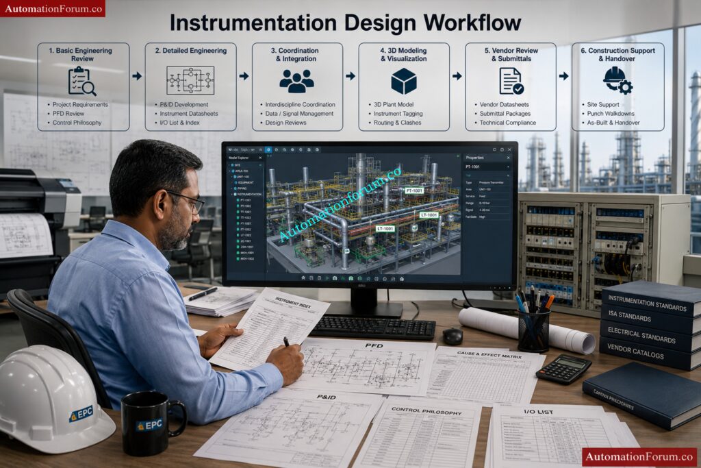
What Is the Complete Workflow of Instrumentation Design?
The instrumentation design workflow starts from understanding process requirements and ends with commissioning support and final as-built documentation.
Typical instrumentation design workflow:
1. Review Basic Engineering Inputs
- Study Process Flow Diagrams (PFDs)
- Review Piping and Instrumentation Diagrams (P&IDs)
- Understand client specifications and project standards
- Review equipment layouts and hazardous area drawings
2. Prepare Engineering Documents
- Instrument Index
- Instrument Datasheets
- I/O List
- Control Philosophy
- Cause & Effect Matrix
3. Perform Detailed Engineering
- Prepare hook-up drawings
- Develop loop diagrams
- Prepare cable schedules and JB schedules
- Design instrument layouts and cable tray routing
4. Coordinate with Other Departments
- Coordinate with piping for process connections
- Coordinate with electrical for power requirements
- Coordinate with civil and structural teams for supports
5. Perform 3D Modeling and Review
- Verify accessibility and maintenance space
- Perform clash checking
- Optimize cable routing and instrument locations
6. Procurement and Vendor Coordination
- Review vendor drawings
- Verify compatibility with project specifications
7. Construction and Commissioning Support
- Resolve site technical queries
- Support loop checking and testing
- Assist during FAT and SAT
- Update as-built drawings after commissioning
This workflow ensures smooth project execution from engineering to plant startup.
What Are the Major Deliverables in Instrumentation Engineering?
Instrumentation engineering produces several documents and drawings required for design, procurement, installation, testing, and commissioning activities.
Major instrumentation deliverables include:
Engineering Deliverables
- Instrument Index
- Instrument Datasheets
- I/O List
- Control Philosophy
- Alarm and Trip List
- Cause & Effect Matrix
Installation Deliverables
- Instrument Hook-up Drawings
- Instrument Location Layouts
- Cable Tray Layouts
- Junction Box Layouts
- Air Header Layouts
- Instrument Support Drawings
Wiring and Cable Deliverables
- Loop Diagrams
- Cable Schedules
- JB Schedules
- Interconnection Diagrams
- Wiring Drawings
Control System Deliverables
- PLC/DCS Architecture Drawings
- Logic Diagrams
- HMI Graphics Documents
Construction and Commissioning Deliverables
- Material Take-Off (MTO)
- Red Markup Drawings
- As-built Drawings
- Loop Test Reports
These deliverables are essential for engineering, construction, operation, and maintenance of the plant.
What Is the Difference Between an Instrument Engineer and an Instrument Designer?
Instrument Engineers and Instrument Designers work together, but their responsibilities are different.
| Instrument Engineer | Instrument Designer |
| Performs engineering calculations | Prepares detailed drawings |
| Selects instruments and valves | Develops layouts and routing |
| Creates technical specifications | Creates installation details |
| Handles control philosophy | Handles CAD drafting |
| Reviews vendor technical documents | Prepares construction drawings |
| Performs sizing calculations | Develops hook-up drawings |
| Responsible for engineering decisions | Responsible for drawing accuracy |
| Focuses on system performance | Focuses on practical installation |
Simple explanation:
- Instrument Engineer decides what should be used
- Instrument Designer decides how and where it should be installed
Both roles are important for successful project execution.
Which Standards Are Followed in Instrumentation Design?
Instrumentation design follows international standards to ensure safety, reliability, compatibility, and proper engineering practices.
Commonly used standards are:
ISA Standards
- ISA 5.1 → Instrument symbols and identification
- ISA 84 → Safety Instrumented Systems
- ISA 18.2 → Alarm Management
IEC Standards
- IEC 61511 → Functional Safety
- IEC 60079 → Hazardous Area Classification
- IEC 61131 → PLC Systems
Other International Standards
- API Standards
- ANSI Standards
- NFPA Standards
- IEEE Standards
- ISO Standards
- NEMA Standards
Additional project requirements:
- Client standards
- Company engineering standards
- Local electrical regulations
- Plant safety standards
Following standards ensures safe and reliable plant operation and reduces engineering errors.
Which Documents Are Received from the Process Department?
The process department provides several important input documents required for instrumentation engineering and design activities.
Main documents received from process department are:
- Process Flow Diagram (PFD)
- Piping and Instrumentation Diagram (P&ID)
- Line List
- Equipment List
- Utility Summary
- Process Datasheets
- Control Philosophy
- Shutdown Philosophy
- Cause & Effect Matrix
- Hazardous Area Classification Drawings
- Heat and Material Balance
- Process Operating Conditions
Importance of these documents:
These documents help instrumentation engineers:
- Select suitable instruments
- Develop control strategies
- Understand process conditions
- Design safe and reliable systems
Instrumentation design cannot start properly without process department inputs.
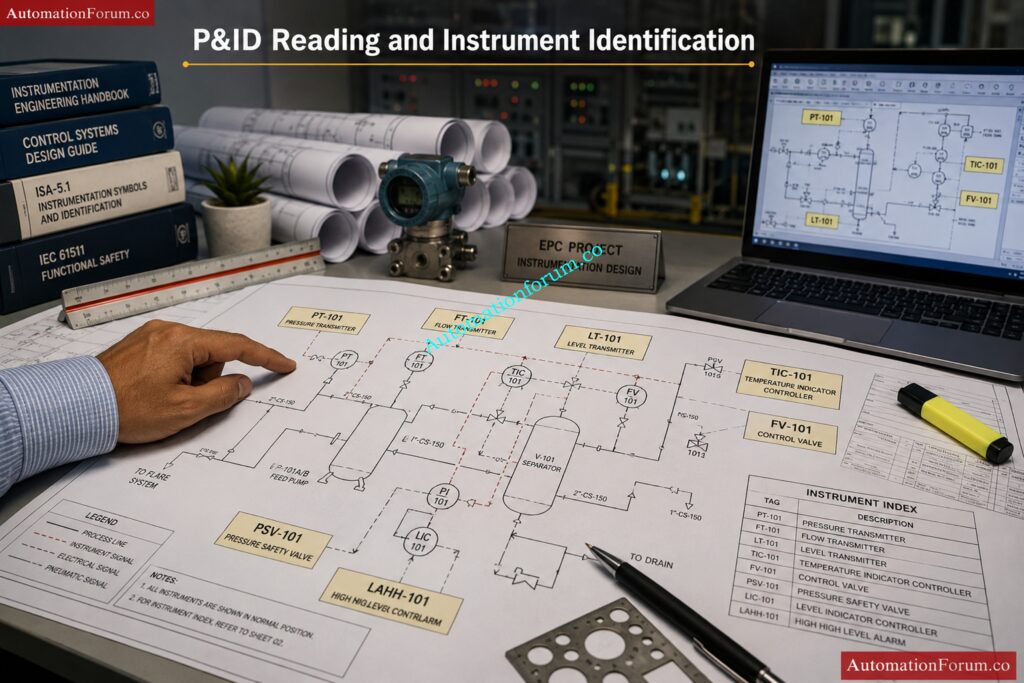
How Do You Read and Interpret P&IDs in Instrumentation Engineering?
P&IDs are the most important drawings in instrumentation engineering because they show the complete process flow, instruments, piping systems, and control loops used in the plant.
Steps to read and interpret a P&ID:
1. Understand Process Flow
- Identify flow direction
- Study process sequence
- Understand plant operation
2. Identify Major Equipment
- Pumps
- Tanks
- Vessels
- Heat exchangers
- Compressors
Examples:
- PT → Pressure Transmitter
- LT → Level Transmitter
- TIC → Temperature Indicating Controller
- FV → Flow Valve
4. Understand Control Loops
Check:
- Measuring instrument
- Controller
- Final control element
5. Identify Signal Types
- Pneumatic signals
- Electrical signals
- Digital communication signals
6. Review Safety Systems
- Shutdown valves
- Trips and interlocks
- Alarm systems
- Emergency shutdown systems
P&IDs are used as the base document for almost all instrumentation engineering activities.
What Checks Should Be Done Before Starting Instrumentation Design?
Before starting instrumentation design, several technical, safety, and engineering checks are performed to avoid future problems during installation and commissioning.
Main checks include:
Document Verification
- Verify latest P&ID revision
- Check approved specifications
- Review vendor documents
Technical Checks
- Verify instrument accessibility
- Check utility availability
- Review hazardous area classification
- Check process conditions and operating parameters
Layout Checks
- Verify equipment locations
- Check maintenance clearance
- Confirm support availability
- Review cable routing feasibility
Interdisciplinary Coordination
- Coordinate with piping department
- Coordinate with electrical department
- Coordinate with civil and structural teams
Additional Checks
- Verify communication protocols
- Check spare philosophy
- Review control room capacity
- Check existing plant constraints in brownfield projects
These checks help reduce rework and improve project quality.
Which Software and Tools Are Used by Instrumentation Designers?
Instrumentation designers use different software tools for drafting, database management, modeling, and control system engineering.
Commonly used software includes:
Drafting and Design Software
- AutoCAD
- MicroStation
- E3D
- SP3D
Instrumentation Engineering Software
- SPI (SmartPlant Instrumentation)
- AVEVA Instrumentation
- COMOS
3D Review and Clash Detection Tools
- Navisworks
- SmartPlant Review
Control System Software
- Siemens PCS7
- Allen Bradley Studio 5000
- Emerson DeltaV
- Yokogawa CENTUM VP
Engineering Utilities
- Microsoft Excel
- Conval
- Loop calculation tools
Communication and Calibration Tools
- HART Communicator
- Modbus configuration tools
- Profibus tools
Knowledge of both engineering software and drafting tools is important for instrumentation design activities.
Which Projects Have You Worked On and What Was Your Role?
Sample Interview Answer:
I was responsible for preparing:
- Instrument location layouts
- Hook-up drawings
- Loop diagrams
- Cable schedules
- Junction box layouts
- Cable tray routing drawings
I also coordinated with process, piping, electrical, and civil departments to ensure proper installation and routing activities. In addition, I participated in 3D model reviews, vendor drawing reviews, and site support activities during construction and commissioning phases.
Crush protocol interviews with these high-value answer strategies: Industrial Communication Protocol Interview Questions and Answers
Instrument Location and Layout Design
What Factors Should Be Considered While Locating Field Instruments?
While locating field instruments, several operational, safety, and maintenance factors must be considered to ensure proper performance and easy accessibility.
Main factors considered are:
- Accessibility for operation and maintenance
- Visibility from operating area
- Safety of personnel
- Distance from process tapping point
- Vibration and temperature effects
- Hazardous area classification
- Availability of supports and structures
- Cable routing feasibility
- Ease of calibration and removal
- Protection from weather conditions
Instruments should be installed in locations where technicians can easily inspect, calibrate, and maintain them without disturbing plant operation. Proper instrument location improves reliability and reduces maintenance time.
What Is the Minimum Clearance Required for Instrument Maintenance?
Adequate clearance must be maintained around instruments to allow safe operation, inspection, calibration, and replacement activities.
Typical maintenance clearances:
- Minimum 750 mm to 1 meter working space around instruments
- Enough clearance for opening covers and removing components
- Access for calibration equipment and hand tools
- Safe movement for maintenance personnel
For large control valves or analyzers, additional clearance may be required for lifting and dismantling activities.
Benefits of proper clearance:
- Easier maintenance activities
- Improved safety
- Reduced downtime
- Better accessibility for calibration
- Prevention of accidental damage
Clearance requirements may vary depending on project standards and client specifications.
What Are the Standard Installation Heights for Instruments?
Instrument installation height is selected to ensure easy operation, visibility, maintenance accessibility, and safety.
Typical installation heights:
- Pressure gauges and local indicators → near eye level
- Transmitters → accessible for calibration
- Junction boxes → reachable without difficulty
- Control valve accessories → easy to inspect and maintain
Common standard heights:
- 1.2 m to 1.5 m from operating floor level for instruments
- Junction boxes generally mounted around 1.0 m to 1.2 m
Important considerations:
- Avoid excessive bending or climbing
- Ensure safe operator access
- Maintain visibility of displays and gauges
- Consider platform and ladder access if mounted at elevation
Correct mounting height improves operator convenience and maintenance efficiency.
Why Should Instruments Not Be Installed Near Vibration Sources?
Instruments should not be installed near vibration sources because vibration can affect measurement accuracy and damage sensitive instrument components.
Problems caused by vibration:
- Fluctuating or unstable readings
- Damage to sensing elements
- Loosening of fittings and tubing
- Premature instrument failure
- Signal disturbances
- Reduced transmitter life
Common vibration sources:
- Pumps
- Compressors
- Rotating machinery
- Reciprocating equipment
Solutions to reduce vibration effects:
- Use remote mounting
- Install vibration-resistant supports
- Use flexible tubing or hoses
- Relocate instruments away from vibration areas
Proper installation improves instrument reliability and measurement stability.
How Do You Ensure Accessibility for Instrument Maintenance?
Accessibility is one of the most important requirements in instrumentation layout design because instruments require periodic inspection, calibration, and servicing.
Methods used to ensure accessibility:
- Maintain sufficient working clearance
- Avoid congested installation locations
- Provide access platforms and ladders
- Ensure easy reach to manifolds and valves
- Avoid installing instruments behind piping or structures
- Provide safe walking and working areas
Additional considerations:
- Easy cable and tubing access
- Safe removal of transmitters and gauges
- Accessibility during plant operation
- Proper lighting around instruments
Good accessibility reduces maintenance time and improves plant safety and operational efficiency.
What Are the Hazardous Area Considerations for Instrument Location?
When instruments are installed in hazardous areas, special safety precautions must be followed to avoid ignition of flammable gases or vapors.
Hazardous area considerations include:
- Use certified hazardous area instruments
- Follow area classification drawings
- Select correct protection type such as Ex d, Ex i, or Ex e
- Use approved cable glands and conduits
- Ensure proper earthing and bonding
- Maintain safe distance from ignition sources
Additional requirements:
- Proper sealing to prevent gas entry
- Correct IP protection rating
- Avoid exposure to excessive heat
- Follow IEC and project safety standards
Proper hazardous area installation is essential for plant safety and regulatory compliance.
How Do You Avoid Clashes with Piping and Equipment?
Clash avoidance is an important activity during instrumentation layout and routing design.
Methods used to avoid clashes:
- Perform 3D model review
- Coordinate with piping and mechanical teams
- Review equipment layouts before routing
- Use SP3D or Navisworks clash detection tools
- Maintain minimum spacing requirements
Areas commonly checked:
- Cable trays
- Instrument stands
- Tubing routing
- Junction box locations
- Access paths
Objectives of clash checking:
- Ensure maintenance accessibility
- Avoid interference during operation
- Prevent installation difficulties
- Reduce field rework
- Improve plant safety
Proper interdisciplinary coordination minimizes construction problems and project delays.
What Are the Weather Protection Requirements for Field Instruments?
Field instruments installed outdoors must be protected against environmental conditions such as rain, sunlight, dust, humidity, and corrosion.
Common weather protection methods:
- Sunshades for transmitters and gauges
- Rain hoods and weather covers
- Weatherproof enclosures
- Corrosion-resistant materials
- Proper IP-rated equipment
Typical protection requirements:
- IP65 or IP66 enclosure protection
- UV-resistant materials
- Stainless steel hardware in corrosive areas
Benefits of weather protection:
- Improves instrument life
- Prevents water ingress
- Reduces calibration drift
- Prevents overheating
- Minimizes corrosion problems
Weather protection is especially important in offshore, chemical, and outdoor process plants.
What Are the Key Instrument Stand Design Considerations?
Instrument stands are designed to provide stable and safe mounting support for field instruments.
Main design considerations:
- Structural strength and rigidity
- Resistance to vibration
- Corrosion resistance
- Proper mounting height
- Accessibility for maintenance
Additional requirements:
- Suitable material selection
- Proper base support
- Easy tubing and cable routing
- Safe operator access
- Compliance with project standards
Common materials used:
- Carbon steel
- Galvanized steel
- Stainless steel
Instrument stands should support the instrument securely without transferring excessive vibration or stress to process connections.
What Are the Common Mistakes in Instrument Layout?
Poor instrument layout can create operational, maintenance, and safety problems during plant operation.
Common mistakes include:
- Insufficient maintenance clearance
- Installing instruments near vibration sources
- Poor accessibility
- Incorrect mounting height
- Improper cable routing
- Installing instruments near hot surfaces
- Poor weather protection
- Congested layout design
- Ignoring hazardous area requirements
- Improper support arrangement
Effects of poor layout:
- Difficult maintenance activities
- Increased plant downtime
- Safety hazards
- Measurement inaccuracies
- Frequent instrument failures
- Additional construction rework
Proper planning and interdisciplinary coordination help avoid these layout mistakes and improve overall plant reliability.
Master critical audit traps before your next ISO audit: Top 60 Calibration Audit Questions Every ISO Auditor Should Ask in Process Plants
Hook-Up Drawings for Instruments and Control Valves
Process Hook-up
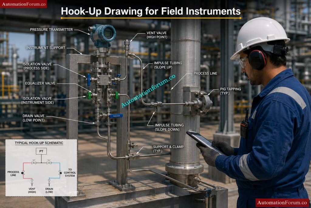
What Is a Process Hook-Up Drawing?
A process hook-up drawing is a detailed installation drawing that shows how an instrument is mechanically connected to the process line or equipment in the field.
A hook-up drawing normally includes:
- Process tapping location
- Root valve arrangement
- Manifold connections
- Impulse tubing routing
- Supports and mounting details
- Drain and vent valves
- Instrument installation method
Purpose of hook-up drawings:
- Ensure proper instrument installation
- Maintain accurate measurement
- Follow standard installation practices
- Provide guidance for construction and maintenance teams
These drawings are widely used during installation, commissioning, and maintenance activities.
How Is a DP Transmitter Hook-Up Done for Liquid Service?
In liquid service, the DP transmitter is normally installed below the process tapping point so that the impulse lines remain completely filled with liquid.
Typical arrangement:
- Both impulse lines slope downward toward the transmitter
- Equal elevation of impulse lines is maintained
- Isolation valves and manifolds are installed near the transmitter
Reasons for this arrangement:
- Prevent air trapping
- Maintain stable measurement
- Ensure accurate differential pressure reading
Important considerations:
- Short impulse tubing length preferred
- Proper support for tubing required
- Avoid vibration areas
This arrangement helps maintain a constant liquid head in both impulse lines.
How Is a DP Transmitter Hook-Up Done for Steam Service?
In steam service, condensate pots are used to protect the transmitter from high-temperature steam and maintain equal condensate levels in both impulse lines.
Typical arrangement:
- Condensate pots installed at equal height
- Transmitter mounted below condensate pots
- Impulse lines filled with condensate
Main objectives:
- Protect transmitter from excessive temperature
- Maintain equal pressure reference
- Improve measurement stability
Additional considerations:
- Equal impulse line length preferred
- Proper slope required for condensate flow
- Insulation may be used in some services
Correct steam hook-up arrangement is critical for accurate DP measurement.
What Is the Purpose of a Root Valve in Instrument Hook-Up?
A root valve is the primary isolation valve installed between the process line and the instrument impulse line.
Main purposes of root valve:
- Isolate instrument from process
- Allow safe maintenance and calibration
- Prevent process leakage during servicing
- Enable instrument replacement without plant shutdown
Advantages:
- Improves safety
- Reduces downtime
- Simplifies maintenance activities
Root valves are usually installed as close as possible to the process tapping point.
Why Are Manifold Valves Used in Instrumentation?
Manifold valves are used with pressure and differential pressure transmitters to simplify isolation, equalization, venting, and calibration activities.
Types of manifolds:
- 2-valve manifold
- 3-valve manifold
- 5-valve manifold
Main functions:
- Isolate transmitter
- Equalize pressure
- Vent trapped gas
- Drain trapped liquid
- Support calibration activities
Benefits:
- Easier maintenance
- Improved safety
- Reduced tubing connections
- Simplified calibration
Manifolds are widely used in DP transmitter installations.
What Are the Impulse Tubing Slope Requirements?
Impulse tubing slope is important to prevent gas or liquid accumulation inside the tubing which may affect measurement accuracy.
Slope requirements:
For liquid service:
- Tubing should slope downward toward transmitter
For gas service:
- Tubing should slope upward toward process line
For steam service:
- Proper condensate leg arrangement required
Importance of proper slope:
- Prevent air pockets
- Prevent liquid trapping
- Improve measurement accuracy
- Reduce response delay
Typical slope maintained:
- Around 1:10 minimum slope
Proper tubing slope improves instrument reliability and stability.
What Is a Condensate Pot Arrangement?
Condensate pots are used in steam applications to maintain equal condensate head on both sides of a DP transmitter.
Purpose of condensate pots:
- Protect transmitter from high-temperature steam
- Maintain equal liquid column
- Improve measurement accuracy
Installation requirements:
- Both pots mounted at same elevation
- Equal impulse line length preferred
- Transmitter installed below pots
Advantages:
- Stable differential pressure reading
- Reduced temperature exposure
- Better transmitter protection
Condensate pots are commonly used in steam flow and steam pressure measurement applications.
Why Are Vents and Drains Provided in Hook-Up Drawings?
Vent and drain valves are provided in instrument hook-ups to remove trapped gas or liquid from impulse lines and manifolds.
Vent valves are used to:
- Remove trapped air or gas
- Assist calibration
- Improve accuracy in liquid service
Drain valves are used to:
- Remove trapped liquid
- Clean impulse lines
- Assist maintenance activities
Benefits:
- Improve measurement stability
- Prevent false readings
- Simplify commissioning and calibration
Proper vent and drain arrangement improves overall instrument performance.
What Are the Tubing Material Selection Criteria?
Tubing material selection depends on process conditions, environmental conditions, and safety requirements.
Main selection criteria:
- Process fluid compatibility
- Pressure rating
- Temperature rating
- Corrosion resistance
- Mechanical strength
- Installation environment
Common tubing materials:
- Stainless steel
- Copper
- Monel
- PTFE tubing
Additional considerations:
- Vibration resistance
- Hazardous area requirements
- Cost and availability
Stainless steel tubing is most commonly used due to its corrosion resistance and durability.
What Are the Common Installation Mistakes in Hook-Ups?
Improper hook-up installation can create operational and maintenance problems.
Common mistakes include:
- Incorrect tubing slope
- Long impulse tubing runs
- Poor tubing support
- Improper manifold orientation
- Leakage at fittings
- Wrong valve installation
- Improper vent and drain arrangement
- Installing transmitter at wrong elevation
Effects of poor installation:
- Inaccurate measurement
- Slow response
- Frequent maintenance
- Instrument damage
- Process instability
Following standard hook-up practices helps avoid these problems.
Ace PLC interviews using proven field-tested concepts fast: PLC (Programmable Logic Controllers) Interview Questions and Answers
Pneumatic Hook-Up and Control Valve Accessories
What Is a Control Valve Pneumatic Hook-Up?
A pneumatic hook-up drawing for a control valve shows how pneumatic components are connected between the air supply and valve actuator.
Main components included:
- Air filter regulator
- Solenoid valve
- Positioner
- Volume booster
- Pneumatic tubing
- Actuator connections
Main functions:
- Supply clean regulated air
- Control valve movement
- Provide fail-safe operation
- Improve actuator response
Pneumatic hook-up drawings are important for proper valve operation and shutdown functionality.
What Are Air Sets and Their Components?
An air set is a combination unit used to clean and regulate compressed instrument air before supplying it to pneumatic instruments.
Main components:
- Air filter
- Pressure regulator
- Pressure gauge
Functions:
- Remove moisture and dirt
- Maintain stable air pressure
- Protect pneumatic instruments
Importance:
- Improves instrument life
- Prevents air contamination
- Ensures stable operation
Air sets are commonly installed before control valve positioners and pneumatic instruments.
What Is an FR Filter Regulator?
FR stands for Filter Regulator.
It is used in pneumatic systems to:
- Filter contaminated air
- Remove moisture and dust
- Regulate output air pressure
Advantages:
- Protects pneumatic devices
- Improves reliability
- Maintains stable instrument air pressure
Common applications:
- Control valves
- Pneumatic actuators
- Positioners
- Solenoid valves
Clean instrument air is essential for reliable pneumatic system performance.
How Are Positioner Connections Made?
A valve positioner receives a control signal and adjusts actuator air pressure to position the valve accurately.
Typical connections include:
- Instrument air supply
- Input signal connection
- Output to actuator
- Feedback linkage from valve stem
Purpose of positioner:
- Improve valve accuracy
- Reduce hysteresis
- Improve response time
- Ensure correct valve positioning
Types of signals:
- Pneumatic signal
- 4–20 mA electrical signal
- Digital communication signal
Positioners improve overall control valve performance.
What Is Fail-Safe Action in Control Valves?
Fail-safe action defines the valve position during loss of air supply or power failure.
Common fail-safe actions:
- Fail Open (FO)
- Fail Close (FC)
- Fail Last Position (FL)
Purpose:
- Protect process equipment
- Ensure plant safety
- Prevent hazardous conditions
Selection depends on:
- Process requirement
- Safety philosophy
- Shutdown logic
Fail-safe action is decided during engineering design based on process safety requirements.
Why Are Volume Boosters Used?
Volume boosters are used to increase air flow capacity to pneumatic actuators for faster valve movement.
Main purposes:
- Improve stroking speed
- Reduce valve response time
- Handle large actuators
Applications:
- Large control valves
- Fast shutdown valves
- Emergency shutdown systems
Benefits:
- Faster actuator operation
- Improved control performance
- Better shutdown response
Volume boosters are commonly used in critical control applications.
How Is a Solenoid Valve Installed?
Solenoid valves are installed in pneumatic systems to control air flow to actuators during normal and shutdown conditions.
Installation considerations:
- Correct flow direction
- Proper electrical connection
- Accessible mounting location
- Weather protection for outdoor installation
Functions:
- Shutdown operation
- Remote ON/OFF control
- Emergency isolation
Common applications:
- ESD valves
- Shutdown valves
- Pneumatic actuators
Solenoid valves play an important role in safety instrumented systems.
How do you support and route pneumatic tubing?
Proper tubing support and routing are important to avoid vibration, leakage, and tubing damage.
Good routing practices:
- Use tubing clamps and supports
- Avoid sharp bends
- Maintain neat routing
- Avoid hot surfaces
- Maintain proper spacing
Additional considerations:
- Avoid vibration areas
- Protect tubing from mechanical damage
- Use proper bending radius
Proper routing improves reliability and appearance of installation.
What Are the Common Mistakes in Pneumatic Hook-Ups?
Improper pneumatic hook-up installation can create operational problems in control valves and pneumatic systems.
Common mistakes include:
- Air leakage
- Wrong tubing size
- Improper tubing routing
- Loose fittings
- Incorrect solenoid installation
- Poor tubing support
- Contaminated air supply
Effects:
- Slow valve response
- Valve hunting
- Unstable control
- Instrument failure
Good installation practices help improve system performance and reliability.
How Do You Test Pneumatic Systems?
Pneumatic systems are tested before commissioning to ensure leak-free and reliable operation.
Common tests performed:
- Air leak test
- Pressure test
- Stroke test
- Solenoid functional test
- Positioner calibration
- Fail-safe testing
Additional checks:
- Verify air pressure
- Check tubing connections
- Confirm actuator movement
- Verify shutdown action
Testing ensures proper operation of control valves and pneumatic instruments before plant startup.
Dominate automation interviews with expert-level system insights today: Top Industrial Automation & Control System Interview Questions
Cable Tray Routing and Cable Management
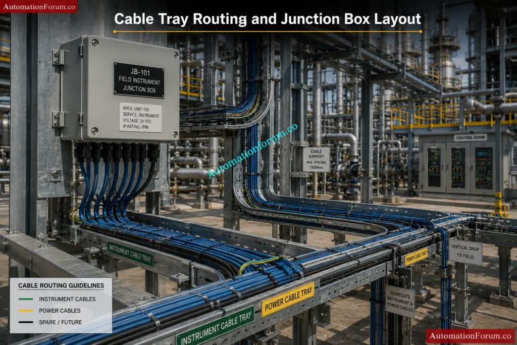
How Do You Start Cable Tray Routing for a Project?
Cable tray routing starts after reviewing all engineering input documents and understanding the plant layout requirements.
Initial steps include:
- Study plot plan and equipment layout
- Review instrument location drawings
- Review cable schedule and cable quantity
- Identify control room and junction box locations
- Understand hazardous area classification
- Review piping and structural layouts
Routing objectives:
- Provide shortest practical cable path
- Maintain accessibility for maintenance
- Avoid congestion and clashes
- Ensure safe cable segregation
Important considerations:
- Future expansion requirements
- Support availability
- Plant operating conditions
- Safety and maintenance access
Proper planning at the beginning helps reduce routing modifications during construction.
What Factors Are Considered During Cable Tray Routing?
Several technical and practical factors are considered during cable tray routing to ensure safe and efficient cable installation.
Main factors include:
- Cable quantity and size
- Cable segregation requirements
- Accessibility for maintenance
- Hazardous area classification
- Future expansion capacity
- Structural support availability
- Heat sources and hot piping
- Distance between equipment
Additional considerations:
- Avoiding water accumulation
- Safe routing through process areas
- Proper bending radius
- Interdisciplinary coordination
Good routing design improves cable protection, maintenance accessibility, and overall plant reliability.
How Do You Calculate Cable Tray Width?
Tray width is calculated based on the total cable quantity, cable diameter, and allowable tray fill percentage.
Calculation steps:
- Determine number of cables
- Identify cable diameters
- Calculate total cable area
- Apply tray fill percentage standard
- Select nearest standard tray size
Additional considerations:
- Spare capacity for future cables
- Cable separation requirements
- Ventilation and heat dissipation
- Cable bending space
Common tray sizes:
- 100 mm
- 300 mm
- 450 mm
- 600 mm
Correct tray sizing prevents overcrowding and simplifies future cable installation.
What Is Cable Tray Fill Percentage and What Is the Limit?
Tray fill percentage indicates how much tray space is occupied by cables compared to total tray capacity.
Typical tray fill limits:
- Normally maintained around 40% to 50%
- Additional space kept for future expansion
- Excessive filling should be avoided
Reasons for limiting tray fill:
- Allow heat dissipation
- Simplify cable pulling
- Reduce cable damage risk
- Maintain proper ventilation
Problems caused by overfilling:
- Cable overheating
- Difficult maintenance
- Increased cable damage
- Future expansion difficulties
Tray fill percentage is controlled according to project standards and electrical regulations.
Why Should Spare Capacity Be Maintained in Cable Trays?
Spare tray capacity is maintained to accommodate future cable additions and plant modifications.
Reasons for spare capacity:
- Future plant expansion
- Additional instrumentation
- Modification projects
- Replacement of damaged cables
Typical spare capacity:
- Around 20% to 30% extra tray space
Advantages:
- Reduces future tray installation work
- Simplifies cable additions
- Minimizes shutdown requirements
- Reduces project modification cost
Proper spare planning improves long-term plant flexibility and maintainability.
What Are the Cable Segregation Rules?
Cable segregation is required to prevent electrical interference and improve safety.
Common segregation practices:
- Separate power and instrument cables
- Separate analog and digital signal cables
- Separate fire and gas cables
- Separate fiber optic cables
- Separate intrinsically safe and non-IS cables
Methods of segregation:
- Different trays
- Metallic barriers
- Minimum spacing between cable groups
Benefits:
- Reduces signal interference
- Improves signal quality
- Enhances safety
- Simplifies maintenance
Proper segregation is especially important for low-level instrument signals.
What Is the Difference Between Power Cable Trays and Instrument Cable Trays?
Power cable trays and instrument cable trays are separated because they carry different types of electrical signals.
| Power Cable Tray | Instrument Cable Tray |
| Carries high voltage cables | Carries low-level signal cables |
| Higher electromagnetic interference | Sensitive to interference |
| Used for motors and power systems | Used for transmitters and control systems |
| Larger cable sizes | Smaller cable sizes |
| Heavy current carrying cables | Low current signal cables |
Importance of separation:
- Prevent signal disturbance
- Improve control system stability
- Maintain measurement accuracy
Separate tray routing improves overall system reliability.
What Are the Minimum Tray Spacing Requirements?
Proper spacing between trays is maintained for ventilation, cable installation, and maintenance accessibility.
Typical spacing requirements:
- Enough space for cable pulling
- Adequate ventilation
- Access for maintenance personnel
- Clearance from piping and structures
Factors affecting spacing:
- Tray size
- Cable quantity
- Heat dissipation requirements
- Maintenance access
Benefits:
- Easier cable installation
- Better cooling
- Improved accessibility
- Reduced cable damage risk
Spacing requirements vary according to project standards and installation conditions.
How Do You Support Cable Trays?
Cable trays are supported using structural supports designed to handle cable weight and environmental loads.
Common support types:
- Wall-mounted brackets
- Floor supports
- Ceiling hangers
- Structural steel supports
Important considerations:
- Tray loading capacity
- Support spacing
- Vibration resistance
- Corrosion protection
Additional requirements:
- Proper alignment
- Structural strength verification
- Safe installation practices
Correct tray support prevents sagging and mechanical damage.
How Do You Avoid Clashes During Cable Tray Routing?
Clash avoidance is an important part of cable tray routing design.
Methods used:
- Perform 3D model review
- Coordinate with piping and structural teams
- Use SP3D or Navisworks clash detection tools
- Review equipment maintenance areas
Areas checked for clashes:
- Piping systems
- HVAC ducts
- Structural members
- Equipment access areas
Benefits:
- Reduces field rework
- Improves installation efficiency
- Prevents maintenance obstruction
- Improves safety
Interdisciplinary coordination is essential for successful routing design.
What Are the Vertical Routing Considerations?
Vertical cable tray routing requires additional support and cable management considerations.
Main considerations:
- Proper cable support spacing
- Secure cable fastening
- Bending radius maintenance
- Accessibility for maintenance
Additional requirements:
- Prevent cable slippage
- Maintain tray alignment
- Proper load distribution
Benefits of proper vertical routing:
- Improved cable protection
- Better appearance
- Safer installation
Vertical trays are commonly used between floors and equipment elevations.
What Are the Underground Cable Routing Considerations?
Underground cable routing requires special protection to prevent cable damage and water ingress.
Main considerations:
- Burial depth
- Soil condition
- Drainage arrangement
- Mechanical protection
Additional requirements:
- Sand bedding
- Warning tape installation
- Cable markers
- Protective conduits where required
Common risks:
- Water accumulation
- Mechanical damage
- Corrosion
- Future excavation damage
Proper underground routing improves cable safety and service life.
How Do You Coordinate Tray Routing with Piping?
Cable tray routing must be coordinated with piping layouts to avoid clashes and maintain safety clearances.
Coordination activities include:
- Review piping GA drawings
- Maintain clearance from hot piping
- Avoid obstructing valve operation areas
- Coordinate support locations
Important considerations:
- Accessibility for both systems
- Thermal effects from piping
- Future maintenance requirements
Benefits:
- Reduced field modifications
- Easier maintenance
- Improved plant safety
Good coordination minimizes construction problems during installation.
What Checks Are Required Before Issue of Tray Drawings?
Several technical checks are performed before releasing tray routing drawings for construction.
Main checks include:
- Clash checking
- Tray loading verification
- Support location verification
- Accessibility review
- Cable segregation verification
Additional checks:
- Correct tray sizing
- Proper routing continuity
- Compliance with standards
- Drawing revision verification
Objectives:
- Eliminate installation problems
- Improve drawing accuracy
- Reduce construction rework
Proper checking improves project quality and construction efficiency.
What Are the Common Mistakes in Cable Tray Routing?
Improper tray routing can create installation, maintenance, and operational problems.
Common mistakes include:
- Overfilled trays
- Poor cable segregation
- Insufficient support spacing
- Routing near hot piping
- Inadequate maintenance clearance
- Sharp bends in routing
- Poor drainage consideration
- Ignoring future expansion
Effects of poor routing:
- Cable overheating
- Difficult maintenance
- Increased signal interference
- Frequent cable damage
- Additional project rework
Proper engineering review and coordination help avoid these common routing mistakes.
Stand out in interviews with 300-plus practical automation answers: 300+ Industrial Automation & Instrumentation Engineering Interview Questions
Junction Box Design and Installation
How Do You Decide the Location of a Junction Box?
The location of a Junction Box (JB) is decided based on cable routing efficiency, accessibility, maintenance convenience, and safety requirements.
Main considerations for JB location:
- Near field instruments to reduce cable length
- Easily accessible for maintenance
- Safe location away from vibration and heat
- Suitable support structure availability
- Proper drainage and weather protection
- Accessibility during plant operation
Additional factors:
- Hazardous area classification
- Cable tray routing feasibility
- Future expansion possibility
- Avoiding congested process areas
Proper JB location helps reduce cable cost, simplifies maintenance, and improves installation quality.
What Factors Are Considered for JB Grouping?
JB grouping is done to organize field cables efficiently and simplify installation and maintenance activities.
Main grouping factors include:
- Process area or unit grouping
- Instrument signal type
- Hazardous area classification
- Cable routing direction
- Distance from field instruments
- Intrinsically safe and non-IS segregation
Additional considerations:
- Number of instruments
- Future expansion requirement
- Ease of troubleshooting
- Cable tray availability
Proper grouping reduces cable congestion and improves system organization.
How Do You Size a Junction Box?
JB sizing is determined based on the number of terminals, cable entries, spare capacity, and installation space requirements.
Main sizing considerations:
- Total number of instrument signals
- Number of terminal blocks required
- Cable gland quantity and size
- Spare terminals and gland space
- Wiring clearance inside JB
Additional factors:
- Hazardous area requirements
- Future expansion
- Heat dissipation
- Ease of maintenance
Typical spare philosophy:
- 20% spare terminals
- 20% spare gland entries
Proper sizing prevents overcrowding and simplifies future modifications.
What Spare Capacity Is Maintained in Junction Boxes?
Spare capacity is maintained in Junction Boxes to support future expansion and modifications.
Typical spare capacity maintained:
- 20% spare terminals
- 20% spare cable glands
- Additional wiring space
Reasons for maintaining spare capacity:
- Future instrument addition
- Plant expansion projects
- Replacement of damaged terminals
- Simplified modification activities
Benefits:
- Reduces future replacement work
- Improves flexibility
- Minimizes shutdown requirements
Proper spare planning improves long-term maintainability of the system.
What Is the Difference Between IS and Non-IS Junction Boxes?
IS (Intrinsically Safe) and Non-IS junction boxes are used for different signal classifications in hazardous areas.
| IS Junction Box | Non-IS Junction Box |
| Used for intrinsically safe signals | Used for standard signals |
| Installed in hazardous areas | Used for normal circuits |
| Requires blue identification | Standard identification used |
| Strict segregation required | Standard wiring practice |
| Energy-limited circuits | Normal electrical circuits |
Important requirements for IS JBs:
- Separate terminals
- Proper grounding
- Certified components
- Segregated wiring
Proper segregation between IS and Non-IS circuits is essential for hazardous area safety.
What Is the Cable Entry Philosophy for Junction Boxes?
Cable entry philosophy defines how cables enter and exit the Junction Box to ensure proper sealing and protection.
Common cable entry practices:
- Bottom cable entry preferred
- Top entry generally avoided
- Separate entries for different cable groups
- Proper gland spacing maintained
Reasons for bottom entry:
- Prevent water ingress
- Improve cable routing appearance
- Reduce moisture accumulation
Additional considerations:
- Easy cable termination
- Maintenance accessibility
- Proper bending radius
Correct cable entry arrangement improves reliability and environmental protection.
Why Should Gland Orientation Be Downward?
Cable glands are normally installed downward to prevent water and moisture from entering the Junction Box.
Advantages of downward gland orientation:
- Prevents rainwater entry
- Reduces moisture accumulation
- Improves enclosure protection
- Prevents corrosion and short circuits
Additional benefits:
- Better drainage
- Improved cable life
- Reduced maintenance issues
Downward gland orientation is considered a standard installation practice for outdoor JBs.
What Is the Drain Arrangement in a Junction Box?
Drain arrangements are provided in Junction Boxes to remove accumulated moisture or condensation.
Common drain arrangements:
- Drain plug at bottom of JB
- Breather-drain combination devices
- Moisture escape provision
Purpose of drain arrangement:
- Prevent water accumulation
- Reduce internal corrosion
- Protect terminals and wiring
- Improve enclosure life
Importance:
Outdoor JBs are exposed to temperature variation and humidity, which can create condensation inside the enclosure.
Proper drain arrangement improves reliability and reduces maintenance problems.
What Are the Earthing Requirements for Junction Boxes?
Proper earthing is required for safety, signal stability, and protection against electrical faults.
Earthing requirements include:
- Internal earth bus bar
- External earth connection
- Proper bonding of enclosure
- Shield grounding arrangement
Additional considerations:
- Separate IS and Non-IS grounding where required
- Low-resistance earth continuity
- Corrosion-resistant earth connections
Benefits of proper earthing:
- Personnel safety
- Protection against electrical faults
- Reduction of signal noise
- Static discharge protection
Correct grounding practices are very important in instrumentation systems.
What Are the Common Installation Problems in Junction Boxes?
Improper JB installation can create operational and maintenance problems.
Common installation problems include:
- Water ingress inside JB
- Loose terminal connections
- Improper cable identification
- Poor gland tightening
- Incorrect earthing
- Overcrowded wiring
- Improper cable bending
Effects of these problems:
- Signal failure
- Short circuits
- Corrosion
- Instrument malfunction
- Difficult troubleshooting
Prevention methods:
- Follow installation standards
- Use proper glands and sealing
- Maintain proper wiring practices
- Perform inspection before commissioning
Proper installation and inspection improve JB reliability and long-term performance.
Sharpen your edge with must-know technical career questions: Essential Skills & Interview Questions for instrumentation and Control Engineers & Technicians
Cable Schedule and Cable Selection
What Is a Cable Schedule?
A cable schedule is a detailed engineering document that contains complete information about all cables used in an instrumentation and electrical system.
A cable schedule normally includes:
- Cable number
- Cable type and size
- Source and destination details
- Cable length
- Routing information
- Termination details
Purpose of cable schedule:
- Cable identification
- Material procurement
- Construction reference
- Commissioning support
- Maintenance and troubleshooting
Cable schedules are widely used during engineering, installation, commissioning, and maintenance phases of a project.
What Information Does a Cable Schedule Contain?
Typical information included:
- Cable number or tag
- Cable type
- Number of cores or pairs
- Cable size
- Source location
- Destination location
- Cable length
- Cable gland details
- Routing path
- Signal type
Additional information may include:
- Cable tray number
- Hazardous area classification
- Communication protocol
- Spare core details
- Installation remarks
This information helps installation and maintenance teams identify cables quickly and accurately.
How Do You Select the Correct Cable Type?
Cable type selection depends on process requirements, signal characteristics, environmental conditions, and installation location.
Main selection criteria:
- Signal type
- Voltage level
- Environmental conditions
- Hazardous area requirements
- Mechanical protection requirement
- Fire resistance requirement
Common cable types:
- Twisted pair cables
- Shielded cables
- Multi-core cables
- Fiber optic cables
- Thermocouple extension cables
Additional considerations:
- Armored or unarmored
- Indoor or outdoor installation
- Temperature rating
- Chemical resistance
Correct cable selection improves signal quality, safety, and cable life.
What Is Multi-Core Cable Selection Philosophy?
Multi-core cables contain multiple conductors inside a single cable sheath and are used to reduce cable quantity and simplify routing.
Multi-core cable selection is based on:
- Number of signals
- Signal type compatibility
- Cable routing distance
- Installation cost optimization
Advantages of multi-core cables:
- Reduced tray space
- Easier installation
- Reduced cable quantity
- Better cable management
Common applications:
- Junction box to control room connections
- Multiple field signals in same area
- Digital and analog signal grouping
Important considerations:
- Signal segregation
- Spare core requirement
- Shielding requirement
Proper selection improves routing efficiency and reduces installation cost.
What Is Pair Shielding in Instrument Cables?
Pair shielding is a protective metallic shield provided around cable pairs to reduce electrical noise and electromagnetic interference.
Purpose of shielding:
- Protect low-level signals
- Reduce EMI and noise
- Improve signal quality
- Prevent signal disturbance
Common shielding types:
- Individual pair shielding
- Overall shielding
- Combination shielding
Applications:
- Analog signal cables
- Communication cables
- Low-level instrument signals
Benefits:
- Improved measurement accuracy
- Stable communication
- Reduced signal interference
Shielded cables are very important in instrumentation systems where accurate signal transmission is required.
How Do You Calculate Cable Core Requirements?
Cable core calculation depends on the number of signals, spare requirements, and signal type.
Calculation steps:
- Identify total required signals
- Determine number of conductors per signal
- Add spare cores
- Select nearest standard cable size
Example:
- One analog signal may require 2 cores
- Solenoid valves may require more cores
- Communication cables may require twisted pairs
Additional considerations:
- Future expansion
- Shielding requirements
- Signal segregation
- Voltage drop considerations
Correct core calculation helps avoid cable shortages and future modification difficulties.
What Is the Difference Between Armored and Unarmored Cable?
Armored and unarmored cables differ mainly in mechanical protection capability.
| Armored Cable | Unarmored Cable |
| Has metallic armor protection | No armor protection |
| Better mechanical strength | Lower mechanical protection |
| Suitable for outdoor and underground use | Suitable for indoor use |
| More resistant to damage | More flexible and lighter |
| Higher installation cost | Lower installation cost |
Armored cable advantages:
- Mechanical protection
- Rodent protection
- Better durability
Unarmored cable advantages:
- Easier handling
- Lower cost
- Flexible installation
Cable type selection depends on installation environment and project requirements.
Where Are Fire-Resistant Cables Used?
Fire-resistant cables are used in critical systems that must continue operating during fire conditions.
Common applications:
- Emergency shutdown systems
- Fire and gas systems
- Emergency lighting systems
- Fire alarm systems
- Safety Instrumented Systems (SIS)
Purpose:
- Maintain circuit integrity during fire
- Ensure safe plant shutdown
- Support emergency systems
Important characteristics:
- High-temperature resistance
- Low smoke emission
- Flame retardant properties
Fire-resistant cables are important for plant safety and emergency operation continuity.
What Is Spare Core Requirement?
Spare cores are extra unused conductors provided inside a cable for future use and maintenance flexibility.
Typical spare core practice:
- 10% to 20% spare cores maintained
- Minimum one spare pair often provided
Reasons for spare cores:
- Future expansion
- Replacement of damaged cores
- Modification flexibility
- Reduced future cable pulling
Benefits:
- Lower modification cost
- Faster maintenance
- Improved flexibility
Spare cores help simplify future plant changes and troubleshooting activities.
How Do You Maintain Cable Numbering Consistency?
Cable numbering consistency is maintained by following a standard project numbering philosophy and database control system.
Methods used:
- Follow project numbering standards
- Use unique cable numbers
- Maintain centralized database
- Use engineering software such as SPI
Additional practices:
- Avoid duplicate numbering
- Maintain revision control
- Verify source and destination details
- Follow area-wise numbering philosophy
Benefits:
- Easy cable identification
- Improved maintenance
- Faster troubleshooting
- Better documentation control
Consistent cable numbering improves overall project organization and maintenance efficiency.
Win EPC interviews with smart project engineering responses: Project Engineering (EPC) Interview Questions & Answers
SP3D in Instrumentation Design
What Is SP3D and What Are Its Uses?
SP3D (SmartPlant 3D) is a 3D engineering design software widely used in oil & gas, power, chemical, and industrial projects for plant modeling and multidisciplinary engineering design.
Main uses of SP3D:
- 3D plant modeling
- Cable tray routing
- Equipment modeling
- Structural modeling
- Instrument location modeling
- Clash detection and interference checking
- Extraction of 2D drawings from 3D model
Advantages of SP3D:
- Improves design accuracy
- Reduces field clashes
- Enhances interdisciplinary coordination
- Simplifies routing activities
- Reduces construction rework
SP3D is commonly used for detailed engineering and construction support activities in large industrial projects.
How Do You Create and Route Trays in SP3D?
Cable trays in SP3D are created using tray routing tools available in the electrical and instrumentation modules.
Steps involved:
- Select tray specification
- Define tray size and type
- Identify routing start and end points
- Route tray along structural paths
- Add bends, tees, reducers, and supports
- Verify elevation and clearance
Important considerations:
- Maintain cable segregation
- Avoid clashes with piping and structures
- Ensure maintenance accessibility
- Maintain proper tray spacing
Additional activities:
- Assign tray hierarchy
- Check tray loading
- Coordinate with other disciplines
Proper tray routing improves installation efficiency and cable management.
What Is Tray Hierarchy in SP3D?
Tray hierarchy defines the parent-child relationship between cable trays in a routing network.
Purpose of tray hierarchy:
- Organize cable routing system
- Define routing paths clearly
- Simplify cable allocation
- Improve routing management
Typical hierarchy arrangement:
- Main tray
- Sub-tray
- Branch tray
Benefits:
- Easier routing control
- Better tray organization
- Simplified cable management
- Improved design clarity
Tray hierarchy is important in large projects with complex cable routing systems.
How Do You Identify Clashes in SP3D?
Clashes are identified in SP3D using interference checking and clash detection tools.
Common clash areas:
- Cable trays with piping
- Trays with structural members
- Instruments with equipment
- Access obstruction areas
Methods used:
- Run interference checking tools
- Perform 3D model review
- Use color-coded clash reports
- Coordinate with other disciplines
Benefits of clash detection:
- Reduce field modification
- Improve construction efficiency
- Prevent installation delays
- Improve plant safety
Early clash detection significantly reduces project rework and cost.
What Is Interference Checking in SP3D?
Interference checking is the process of identifying physical overlap or insufficient clearance between plant components inside the 3D model.
Interference checking is performed for:
- Piping systems
- Cable trays
- Equipment
- Structural members
- HVAC ducts
Main objectives:
- Detect clashes before construction
- Maintain required clearances
- Ensure accessibility
- Improve installation feasibility
Benefits:
- Reduced construction errors
- Improved plant layout quality
- Faster project execution
Interference checking is one of the most important activities in 3D model review.
How Do You Optimize Tray Routing in SP3D?
Tray routing optimization is performed to reduce cable length, improve accessibility, and minimize congestion.
Optimization methods include:
- Selecting shortest practical routing path
- Reducing unnecessary bends
- Avoiding congested areas
- Maintaining proper tray hierarchy
- Improving support placement
Additional considerations:
- Future expansion
- Maintenance accessibility
- Cable segregation
- Structural support availability
Benefits:
- Reduced cable cost
- Easier maintenance
- Improved installation efficiency
- Better plant appearance
Optimized routing improves both engineering quality and construction efficiency.
How Do You Extract 2D Drawings from SP3D?
SP3D allows automatic extraction of 2D drawings directly from the 3D model database.
Commonly extracted drawings:
- Cable tray layouts
- Instrument layouts
- Isometric drawings
- Equipment arrangement drawings
Extraction process:
- Select required model view
- Generate drawing view
- Add dimensions and annotations
- Verify drawing accuracy
- Issue drawing for review
Benefits:
- Reduces drafting time
- Improves drawing consistency
- Minimizes manual errors
- Ensures model and drawing match
Automatic extraction improves engineering productivity and drawing quality.
What Are the Common Modeling Errors in SP3D?
Modeling errors in SP3D can create installation and construction problems if not identified early.
Common modeling errors include:
- Incorrect elevations
- Clash between disciplines
- Improper tray routing
- Wrong equipment orientation
- Missing supports
- Inaccurate dimensions
- Poor accessibility arrangement
Effects of modeling errors:
- Construction delays
- Field rework
- Increased project cost
- Maintenance difficulties
Prevention methods:
- Regular model review
- Interdisciplinary coordination
- Proper checking procedures
Good engineering review practices help minimize modeling errors.
How Do You Coordinate with Other Discipline Models?
Coordination with other disciplines is essential in SP3D projects because multiple departments work within the same 3D model.
Disciplines commonly coordinated:
- Piping
- Mechanical
- Structural
- Electrical
- HVAC
- Civil
Coordination activities include:
- Model review meetings
- Clash resolution discussions
- Routing coordination
- Accessibility verification
Main objectives:
- Avoid design conflicts
- Ensure installation feasibility
- Improve overall plant layout
Good interdisciplinary coordination improves project quality and reduces construction problems.
What Is the Model Review Process in SP3D?
The model review process is performed to verify the accuracy, safety, accessibility, and constructability of the 3D plant model.
Main review activities:
- Clash checking
- Accessibility verification
- Maintenance space verification
- Safety clearance checking
- Equipment operation review
Areas commonly reviewed:
- Cable tray routing
- Instrument locations
- Valve accessibility
- Structural support arrangement
Participants involved:
- Instrumentation team
- Piping team
- Structural team
- Electrical team
- Construction team
Benefits of model review:
- Reduces field modifications
- Improves construction planning
- Enhances plant safety
- Improves maintenance accessibility
Regular model review is critical for successful project execution.
Answer control valve questions like a seasoned expert: Essential Control Valve Interview Questions
Instrument Installation Practices
What Are the Transmitter Mounting Requirements?
Transmitters should be mounted properly to ensure accurate measurement, easy maintenance, and long service life.
Main mounting requirements:
- Easily accessible location
- Vibration-free support
- Proper orientation
- Adequate maintenance clearance
- Safe operator access
Additional considerations:
- Correct elevation based on service type
- Proper impulse tubing routing
- Weather protection for outdoor installation
- Hazardous area compliance
Objectives:
- Accurate measurement
- Easy calibration
- Safe maintenance
- Reliable operation
Proper mounting improves transmitter performance and reduces maintenance problems.
Why Are Liquid Service Transmitters Installed Below the Tapping Point?
Liquid service transmitters are installed below the tapping point so that impulse lines remain completely filled with liquid.
Main reasons:
- Prevent air trapping
- Maintain stable liquid head
- Ensure accurate pressure transmission
Benefits:
- Improved measurement accuracy
- Stable transmitter response
- Reduced calibration problems
Additional requirements:
- Downward impulse line slope
- Proper tubing support
- Short tubing length preferred
This installation method is standard practice for liquid service applications.
Why Are Gas Service Transmitters Installed Above the Tapping Point?
Gas service transmitters are normally installed above the tapping point to prevent liquid accumulation inside impulse tubing.
Main reasons:
- Prevent condensate collection
- Maintain clean gas impulse path
- Improve measurement accuracy
Benefits:
- Stable pressure measurement
- Reduced maintenance
- Faster response time
Additional considerations:
- Upward tubing slope toward process
- Proper venting arrangement
Correct installation helps avoid false pressure readings.
What Are the Impulse Tubing Support Requirements?
Impulse tubing should be properly supported to avoid vibration, sagging, and mechanical damage.
Main support requirements:
- Use tubing clamps and supports
- Maintain proper spacing between supports
- Avoid excessive bending
- Prevent tubing vibration
Additional considerations:
- Protect from mechanical damage
- Avoid contact with hot surfaces
- Maintain proper slope
Benefits:
- Improved reliability
- Reduced leakage risk
- Better appearance
- Longer tubing life
Proper support improves measurement stability and installation quality.
What Are the Slope Requirements for Tubing?
Impulse tubing slope is important to avoid gas or liquid accumulation inside the tubing.
Typical slope requirements:
Liquid service:
- Tubing slopes downward toward transmitter
Gas service:
- Tubing slopes upward toward process tapping point
Steam service:
- Equal condensate arrangement maintained
Importance of proper slope:
- Prevent trapped air or liquid
- Improve measurement accuracy
- Reduce response delay
Proper slope arrangement improves instrument performance and stability.
What Are the Heat Tracing Requirements?
Heat tracing is used to maintain process temperature and prevent freezing or solidification inside impulse lines and instruments.
Main requirements:
- Maintain required process temperature
- Ensure uniform heating
- Protect tubing and instruments
- Proper insulation arrangement
Common applications:
- Steam service
- Viscous fluids
- Outdoor cold environments
Types of heat tracing:
- Electrical heat tracing
- Steam tracing
Proper heat tracing improves measurement reliability in low-temperature conditions.
How Do You Prevent Vibration in Instruments?
Instrument vibration can affect measurement accuracy and damage sensitive components.
Methods to reduce vibration:
- Install rigid supports
- Use remote mounting
- Use flexible tubing or hoses
- Relocate instruments away from vibration sources
Common vibration sources:
- Pumps
- Compressors
- Rotating machinery
Benefits of vibration control:
- Improved measurement stability
- Reduced maintenance
- Longer instrument life
Proper vibration prevention improves reliability and operating performance.
What Are the Requirements for Instrument Stands?
Instrument stands are designed to provide safe and stable support for field instruments.
Main requirements:
- Structural strength
- Corrosion resistance
- Proper mounting height
- Accessibility for maintenance
- Vibration resistance
Additional considerations:
- Proper base support
- Safe routing of tubing and cables
- Compliance with project standards
Common materials used:
- Carbon steel
- Galvanized steel
- Stainless steel
Proper stand design improves installation safety and equipment reliability.
How Do You Protect Instruments from Weather?
Outdoor instruments require protection from environmental conditions such as rain, sunlight, humidity, and dust.
Common protection methods:
- Sunshades
- Rain hoods
- Weatherproof enclosures
- Corrosion-resistant materials
Additional requirements:
- IP-rated equipment
- Proper gland sealing
- UV-resistant materials
Benefits:
- Improved instrument life
- Reduced corrosion
- Better reliability
- Reduced maintenance
Weather protection is very important in outdoor and offshore installations.
What Are the Typical Installation Mistakes?
Improper installation can create operational and maintenance problems in instrumentation systems.
Common installation mistakes include:
- Incorrect transmitter elevation
- Improper tubing slope
- Poor tubing support
- Wrong manifold installation
- Improper grounding
- Inadequate weather protection
Effects of poor installation:
- Measurement errors
- Leakage problems
- Instrument damage
- Increased maintenance
- Plant downtime
Prevention methods:
- Follow standard installation practices
- Perform inspection before commissioning
- Verify installation against drawings
Proper installation practices improve safety, reliability, and long-term system performance.
Nail gas turbine instrumentation interviews with confidence: Top Essential Gas Turbine Instrumentation Interview Questions and Answers
Hazardous Area Design and Safety
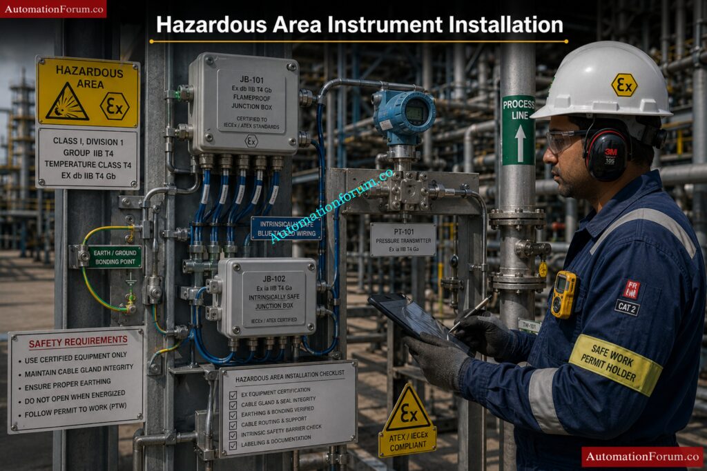
What Is Hazardous Area Classification?
Hazardous area classification is the process of identifying and classifying locations where flammable gases, vapors, or dust may be present in sufficient quantity to create fire or explosion hazards.
Purpose of hazardous area classification:
- Ensure safe equipment selection
- Prevent ignition sources
- Improve plant safety
- Comply with international standards
Classification is based on:
- Type of hazardous material
- Frequency of hazardous atmosphere presence
- Duration of exposure
- Ventilation conditions
Common industries using hazardous area classification:
- Oil & gas
- Refineries
- Chemical plants
- Pharmaceutical industries
- Power plants
Proper hazardous area classification is essential for safe installation of electrical and instrumentation equipment.
What Is the Difference Between Zone 0, Zone 1 and Zone 2?
Hazardous areas are divided into zones based on the probability and duration of explosive gas atmosphere presence.
| Zone | Description |
| Zone 0 | Explosive gas atmosphere continuously present or present for long periods |
| Zone 1 | Explosive gas atmosphere likely during normal operation |
| Zone 2 | Explosive gas atmosphere not likely during normal operation and occurs only for short duration |
Examples:
- Zone 0 → Inside storage tanks
- Zone 1 → Around pump seals or process vents
- Zone 2 → Areas surrounding Zone 1
Importance of zoning:
- Determines equipment protection type
- Defines installation practices
- Helps ensure operational safety
Correct zone classification is critical for hazardous area equipment selection.
What Is an Intrinsically Safe System?
An intrinsically safe (IS) system is a protection technique where electrical energy is limited to a level that cannot ignite a hazardous atmosphere.
Main features of IS systems:
- Low voltage and current
- Limited spark energy
- Safe operation in hazardous areas
Components commonly used:
- IS barriers
- IS transmitters
- IS junction boxes
- IS field devices
Advantages:
- High level of safety
- Maintenance possible in live condition
- Lower installation cost compared to explosion-proof systems
Common applications:
- Transmitters
- Temperature sensors
- Flow instruments
- Communication systems
Intrinsic safety is widely used in instrumentation systems located in hazardous areas.
What Is the Difference Between Ex d, Ex e and Ex i?
Ex protection methods are different techniques used to make equipment safe for hazardous areas.
| Protection Type | Meaning | Main Principle |
| Ex d | Flameproof | Contains internal explosion inside enclosure |
| Ex e | Increased Safety | Prevents sparks and excessive temperature |
| Ex i | Intrinsic Safety | Limits electrical energy to prevent ignition |
Ex d:
- Heavy enclosure
- Used for motors and junction boxes
- Can withstand internal explosion
Ex e:
- No sparking components
- Improved insulation and safety design
Ex i:
- Low-energy circuits
- Commonly used in instrumentation
Selection depends on area classification and application requirement.
What Is IP Rating in Instrumentation?
IP (Ingress Protection) rating defines the degree of protection provided by an enclosure against dust and water entry.
IP rating structure:
- First digit → Protection against solid particles
- Second digit → Protection against water
Common IP ratings:
| IP Rating | Protection |
| IP65 | Dust tight and water jet protection |
| IP66 | Heavy water jet protection |
| IP67 | Temporary immersion protection |
Importance in instrumentation:
- Prevents water ingress
- Protects internal components
- Improves equipment reliability
Outdoor instruments generally require higher IP ratings for environmental protection.
What Are the Cable Gland Requirements in Hazardous Areas?
Cable glands used in hazardous areas must be certified and suitable for the hazardous zone classification.
Main requirements:
- Hazardous area certified glands
- Proper sealing arrangement
- Correct thread type
- Suitable material selection
Additional considerations:
- Flameproof sealing for Ex d equipment
- Weatherproof protection
- Mechanical cable protection
- Proper grounding continuity
Common gland materials:
- Brass
- Nickel-plated brass
- Stainless steel
Proper gland installation prevents gas entry and maintains enclosure protection.
What Is Purge and Pressurization?
Purge and pressurization is a protection technique where clean air or inert gas is used to maintain positive pressure inside an enclosure to prevent hazardous gas entry.
Main principle:
- Hazardous gas is kept outside enclosure
- Internal pressure maintained higher than surrounding atmosphere
Applications:
- Analyzer systems
- Control panels
- Motor enclosures
- Electronic cabinets
Advantages:
- Allows use of standard equipment inside enclosure
- Suitable for large enclosures
- Provides continuous protection
Important requirements:
- Pressure monitoring
- Purging sequence control
- Alarm systems
This protection method is commonly used for large electrical and instrumentation panels.
What Is Gas Group and Temperature Class?
Gas group and temperature class define the characteristics of hazardous gases and the allowable surface temperature of equipment.
Gas groups:
| Gas Group | Example |
| IIA | Propane |
| IIB | Ethylene |
| IIC | Hydrogen, Acetylene |
Temperature classes:
| Temperature Class | Maximum Surface Temperature |
| T1 | 450°C |
| T2 | 300°C |
| T3 | 200°C |
| T4 | 135°C |
| T5 | 100°C |
| T6 | 85°C |
Importance:
- Prevents ignition of hazardous gases
- Ensures safe equipment operation
- Helps select correct hazardous area equipment
Equipment temperature must always remain below gas ignition temperature.
What Are the Earthing Requirements in Hazardous Areas?
Proper earthing is essential in hazardous areas to prevent static discharge, electrical faults, and ignition risks.
Earthing requirements include:
- Proper equipment grounding
- Bonding continuity
- Low-resistance earth path
- Shield grounding for instrumentation cables
Additional requirements:
- Separate IS grounding where required
- Corrosion-resistant earth connections
- Periodic earth continuity testing
Benefits:
- Personnel safety
- Static electricity control
- Fault current protection
- Improved signal stability
Correct grounding practices are critical for safe hazardous area operation.
What Are the Installation Precautions in Hazardous Areas?
Special precautions must be followed during installation to ensure hazardous area safety and compliance with standards.
Main installation precautions:
- Use certified equipment only
- Follow hazardous area drawings
- Maintain proper cable sealing
- Ensure correct grounding and bonding
- Avoid sparks during installation
Additional precautions:
- Use approved cable glands
- Verify enclosure integrity
- Maintain segregation of IS and non-IS circuits
- Follow safe work permit procedures
Common checks before commissioning:
- Certification verification
- Gland tightening inspection
- Earthing continuity testing
- Inspection of flameproof joints
Proper installation practices help prevent explosions, equipment damage, and safety incidents in hazardous areas.
Master instrumentation interviews with practical, job-ready expertise: Instrumentation and Control System Interview Questions and Answers
Common Instrumentation Designer Interview Mistakes
- Giving only theoretical answers
- Ignoring practical installation issues
- Not understanding hazardous areas
- Weak P and ID knowledge
- Lack of coordination understanding
- No knowledge of SPI or SP3D
- Poor explanation of field practices
How to Crack Instrumentation Design Interviews
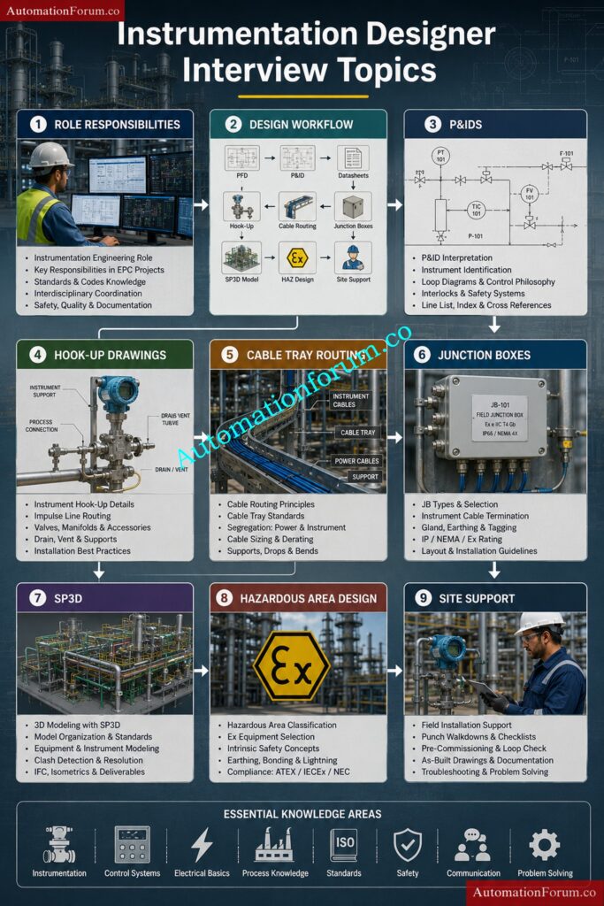
- Study real project drawings
- Learn hook up drawings thoroughly
- Understand cable routing philosophy
- Practice P and ID reading
- Learn SPI and SP3D basics
- Understand hazardous area standards
- Explain answers with practical examples
Key Takeaways for Instrumentation Designer Interview Success
Instrumentation design interviews in EPC industries focus heavily on practical engineering knowledge, field installation practices, coordination skills, and understanding of project workflows. Candidates with strong knowledge of hook up drawings, cable tray routing, hazardous area concepts, SPI, SP3D, and instrument installation practices have better opportunities in Oil and Gas, Petrochemical, LNG, Power Plant, and Process Industries.
This complete guide provides detailed Instrumentation Designer Interview Questions and Answers useful for freshers, experienced professionals, SPI designers, SP3D designers, and instrumentation engineers preparing for EPC interviews.
Refer the elbow link for the Top 30 Refinery Instrumentation Interview Questions and Answers for Maintenance