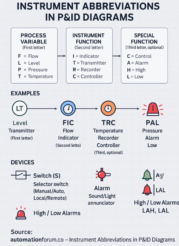
- Generally, the P&ID abbreviations are composed of two or three letters followed by numbers.
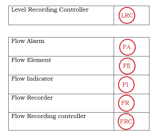
- The process variable such as Flow, Level, Pressure, and Temperature to be controlled is indicated by the first letter in P&ID abbreviation as F, L, P, and T.
- The controlling function of the instrument such as Indication, Recording, Transmitter and controlling is indicated by the second letter in P&ID abbreviation as I, R, T, and C.For example, an instrument abbreviation “LT” indicates a “Level Transmitter”.
- The third letter when included in the instrument abbreviation of P&ID indicates the special function to describe a dual function such as recording and controlling, or indicating and controlling. For example, instrument abbreviations like
- FIC indicates a Flow Indicator and Controller.
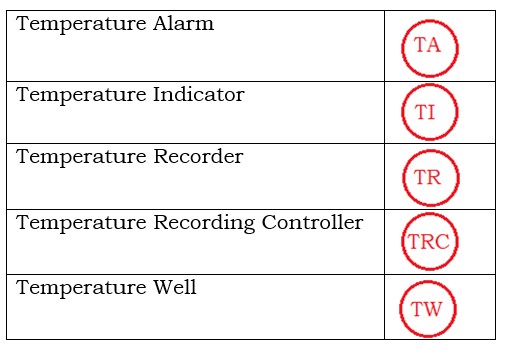
- TRC indicates Temperature Recorder and Controller.
- PAL indicates a Pressure Alarm Low. This PAL describes the alarm function in case of lower pressure conditions.
- The combination of alphabets from A to Z represents the specific functions and identification of instruments in the Piping and Instrumentation Diagram.
- The concept of P&ID is versatile and it is known as the heart and key of industrial processes.
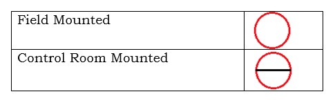
- Representation of instrument abbreviations used in P&IDs with the standard set of symbols defined by ISA 5.1.
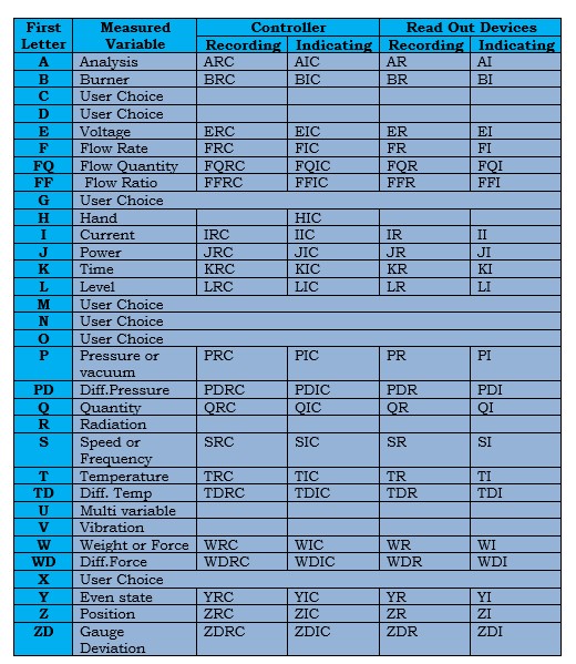
The below table consists of some possible combinations of instrument abbreviations for various process variables.
1.The first column denotes various process variables.
2.The second column denotes the measured variable or indicating variable.
3.The third column denotes the controller function of various process variables such as Recording and Indicating.
4.The fourth column denotes device readout they may be either Recording or Indicating.
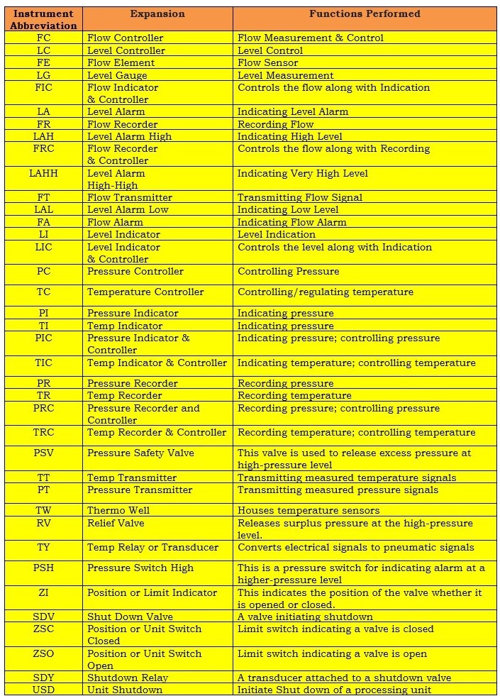
Some instrument abbreviations along with their functions used with P&ID symbols to represent Piping and Instrument diagram are shown in Table 1.
Some possible combinations for various instruments used for measuring variables are represented by the first letter shown in below Table 2.
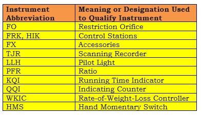
The main objective of making some possible combinations of these process instruments is to understand the purpose for what they are being used in an instrumentation diagram or process flow diagram.
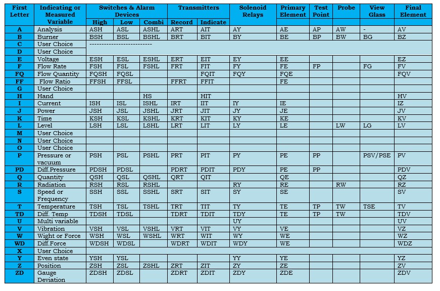
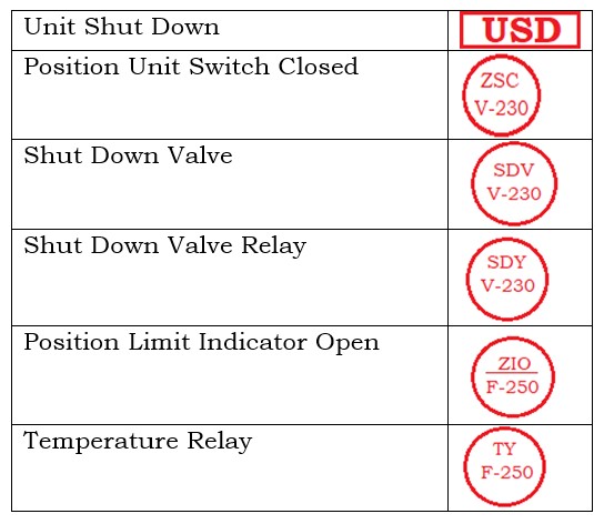
Below Table 3 shows some instrument abbreviations for devices like switches, alarms, transmitters, solenoids, relays, primary elements, test points, probe, view glass, as well as final elements.
What do Tag Numbers on P&ID Diagrams represent?
- The tag numbers on the Piping and instrumentation diagrams representthe identification of the instrument used for the particular control system in a process station.
- These tag numbers are associated with a process variable followed by its function performed such as indicating and controlling process control loops such as Flow, Level, Pressure, and Temperature.
What are Switches & Alarm Devices?
1. Switching Device (S):
- This is known as a selector switch.
- This enables the mode selection from manual mode (M) to auto mode (A in case of DCS), or local (L) to remote (R) by simply rotating.
- It is a device used for switching on or switching off equipment such as motors, pumps, valves, and so on.
- These are used for alarm activation to alert human operators to take special action or for initiating process and safety interlocks used to trip the system.
2. Alarm device (A):
- It is an annunciator device to alert an operator. This may be a sound or lighting device.
- This alarm is triggered by a current signal of 4 20 mA coming from a transmitter.
3. High and Low Alarms:
- The letters H and L indicate the level of High or Low. But during some undefined conditions, these may be omitted.
- In the case of the level transmitter, this signal can be used in the soft program to assign alarms for low and high i.e. LAL & LAH.
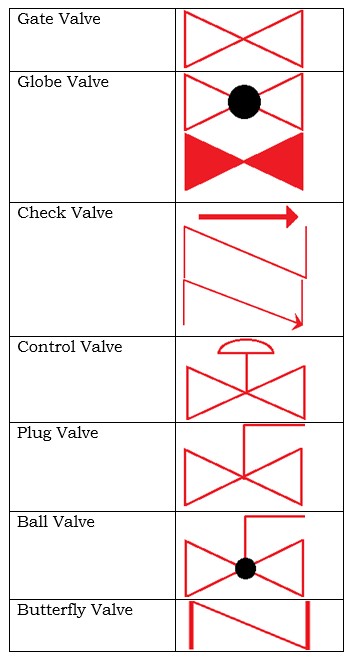
The P&ID diagrams of some instruments shown below are grouped by separate tables

Comprehensive P&ID Abbreviations (A–Z)
This below table covers 50+ key abbreviations across Flow, Level, Pressure, Temperature, Safety, Valves, and Miscellaneous categories.
| Abbreviation | Meaning | Function/Description |
| A | Alarm | Indicates abnormal condition (high, low, etc.) |
| AE | Analyzer Element | Primary sensing device for analyzers |
| AI | Analyzer Indicator | Displays analyzer reading |
| AL | Alarm Low | Alarm condition at low limit |
| AH | Alarm High | Alarm condition at high limit |
| AR | Alarm Recorder | Records alarm events |
| AS | Alarm Switch | Activates alarm circuit |
| C | Control | General control function |
| CV | Control Valve | Final element to regulate flow, pressure, etc. |
| D | Differential | Indicates differential measurement (e.g., DP) |
| DP | Differential Pressure | Measurement of pressure difference |
| E | Element | Primary sensing element |
| FE | Flow Element | Device to measure flow (e.g., orifice, venturi) |
| FI | Flow Indicator | Local or remote display of flow |
| FIC | Flow Indicator Controller | Controls and indicates flow |
| FT | Flow Transmitter | Transmits flow signal (4-20 mA) |
| FY | Flow Relay | Secondary instrument for flow loop |
| FCV | Flow Control Valve | Controls flow in the process |
| G | Glass / Gauge | Visual inspection device (e.g., LG, PG, TG) |
| H | Hand / High | Manual operation or high-level condition |
| HS | Hand Switch | Manual control switch |
| I | Indicator | Displays variable in the field or control room |
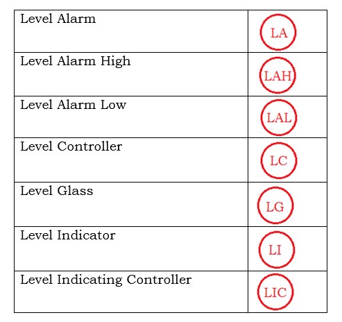
| LIC | Level Indicator Controller | Controls and indicates level |
| LG | Level Gauge | Sight glass for liquid level |
| LSH | Level Switch High | Activates at high-level setpoint |
| LSL | Level Switch Low | Activates at low-level setpoint |
| LT | Level Transmitter | Measures and transmits liquid level |
| LCV | Level Control Valve | Regulates level in vessels/tanks |
| M | Motor | Used in MOVs (Motor Operated Valves) |
| MOV | Motor Operated Valve | Remote operated on/off valve |
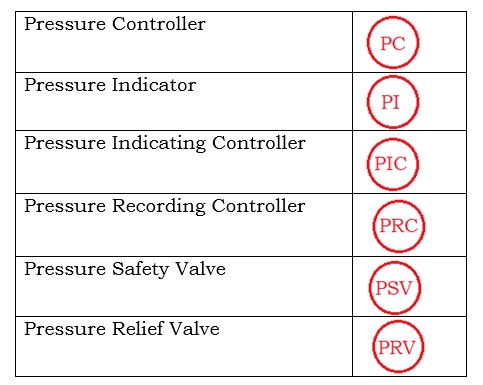
| P | Pressure | Process variable for pressure |
| PG | Pressure Gauge | Local indication of pressure |
| PI | Pressure Indicator | Indicates pressure value |
| PIC | Pressure Indicator Controller | Controls and indicates pressure |
| PSH | Pressure Switch High | Activates alarm/trip on high pressure |
| PSL | Pressure Switch Low | Activates alarm/trip on low pressure |
| PSV | Pressure Safety Valve | Safety relief device for pressure |
| PT | Pressure Transmitter | Measures and transmits pressure |
| PRV | Pressure Relief Valve | Protects system from overpressure |
| PY | Pressure/Position Relay | Used for valve positioners |
| R | Recorder | Records process variable trend |
| T | Temperature | Process variable for temperature |
| TG | Temperature Gauge | Local temperature indication |
| TI | Temperature Indicator | Displays temperature value |
| TIC | Temperature Indicator Controller | Controls and indicates temperature |
| TRC | Temperature Recorder Controller | Records and controls temperature |
| TT | Temperature Transmitter | Measures and transmits temperature |
| TY | Temperature Relay | Relay device in temp loop |
| V | Valve | General valve (manual or control) |
| VG | View Glass | Inspection glass in process line |
| X | Solenoid/On-Off | Device for binary (open/close) control |
| XV | On/Off Valve (Solenoid Operated) | Isolates or diverts flow |
| Y | Relay / Computing Function | Secondary device (e.g., FY, TY, PY) |
| Z | Position | Position measurement (e.g., valve position) |
| SDV | Shutdown Valve | Isolates system in emergency |
| ESD | Emergency Shutdown | Part of safety system (SIS loop) |
| SIS | Safety Instrumented System | Instrumented protection system |
Instrument Function / Process Variable Table
Purpose: Helps readers quickly understand what each instrument does relative to process variables.
| Process Variable | Instrument Function | Typical Abbreviations | Example |
| Flow | Measure / Control | FI, FT, FIC, FCV | FIC-101: Flow Indicator Controller |
| Level | Measure / Control | LT, LIC, LCV, LG | LIC-102: Level Indicator Controller |
| Pressure | Measure / Control | PI, PT, PIC, PSV, PRV | PIC-103: Pressure Indicator Controller |
| Temperature | Measure / Control | TI, TT, TIC, TRC | TIC-104: Temperature Indicator Controller |
Switches and Alarm Devices Table
Purpose: Clarifies the alarm and switch types with their P&ID abbreviations – currently described in text, can be tabular for SEO readability.
| Device Type | Abbreviation | Function | Example |
| Switching Device | S | Selector switch for manual/auto or local/remote | S-101 |
| Alarm Device | A | Alerts operator via sound/light | AH-102 (High Alarm) |
| Low Alarm | LAL | Triggered at low process variable | LAL-103 |
| High Alarm | LAH | Triggered at high process variable | LAH-104 |
Control Function Combinations Table
Purpose: Shows how first, second, and third letters combine for specific functions (highlighting FIC, TIC, TRC, etc.)
| First Letter | Second Letter | Third Letter | Meaning |
| F | I | C | Flow Indicator & Controller |
| T | R | C | Temperature Recorder & Controller |
| P | A | L | Pressure Alarm Low |
| L | I | C | Level Indicator & Controller |
Tag Numbering Example Table
Purpose: Explains how loop numbers and tags are assigned in a P&ID.
| Tag | Meaning | Loop Number / Location |
| LT-101 | Level Transmitter | Loop 101, Tank T-101 |
| FIC-102 | Flow Indicator Controller | Loop 102, Pump P-102 |
| TIC-103 | Temperature Indicator Controller | Loop 103, Heat Exchanger E-103 |
Device Category / Color Coding Table
Purpose: assigns colors to device type for easier field use.
| Device Category | Example Abbreviations | Recommended Color |
| Measuring / Transmitting | FI, FT, TI, TT, LT | Blue |
| Controlling / Final Element | FIC, TIC, LCV, FCV | Green |
| Alarm / Safety | AH, LAL, LAH, PSV, ESD | Red |
| Switch / Relay | S, PY, FY, TY | Yellow |
| Visual / Manual | LG, VG, PG, TG | Grey |