Carefully review the manufacturer’s instructions, technical manuals, and specifications for the C&I equipment before installation. This will help you understand the requirements and guidelines specific to the equipment.
Prioritize safety throughout the installation process. Adhere to all applicable safety regulations, wear appropriate personal protective equipment (PPE), and ensure that the installation area is safe and secure.
The location of instruments should be chosen for ease of operation and maintenance. The position must have the least mechanical vibration and be located in an area where corrosive, hazardous, and explosive gases and dust particles will not deposit, and it must not be subject to a high temperature atmosphere or radiation. However, the precise location will be determined in consultation with the client or consultant. Refer the instrument location layout diagram
Ensure that the C&I equipment is properly grounded and bonded according to the manufacturer’s instructions and local electrical codes. This helps prevent electrical hazards, minimizes interference, and ensures accurate measurements.
Wherever practical, maintenance platforms and approach facilities for all sensing and principal equipment will be provided.
Consider the environmental conditions in which the C&I equipment will operate. Take precautions to protect the equipment from excessive moisture, temperature variations, dust, and other environmental factors that may affect its performance.
Instruments must be housed in weatherproof enclosures, and a suitable canopy must be supplied wherever possible.
High and low pressure impulse lines must not be combined and run simultaneously. In addition, impulse lines for explosive and inert gases must not overlap.
As much as feasible, impulse lines of high pressure steam, toxic gases, and so on shall not be carried into the control room.
In explosion-hazardous circumstances intrinsically safe circuits must be employed.
Plan the routing of cables and wiring carefully to avoid interference, signal loss, and accidental damage. Use appropriate cable management techniques such as cable trays, conduits, and cable ties to keep the installation organized and neat.
Follow the manufacturer’s guidelines for proper terminations and connections of cables, wires, and connectors. Use the recommended tools and techniques to ensure secure and reliable connections.
Separate cable routing is required for high and low voltage lines.
All electrical equipment must meet the standards of the Electricity Rules.
Shock absorbers must be installed wherever strong vibrations are predicted.
Straight pipe lengths of 10 mm on either side must be ensured before and after regulating / control valves.
Instruments containing radioactive isotopes, mercury, or other dangerous compounds must be installed in accordance with legal guidelines issued by authorities.
The usage of junction boxes is not permitted when connecting compensating cables directly to the instruments.
At least 10 dia upstream and 5 dia downstream straight lengths of pipe from bends, tees, branch pipes, and control valves must be provided for orifice plates or flow nozzles.
The control valves are to be placed in their respective positions following the orifice plates.
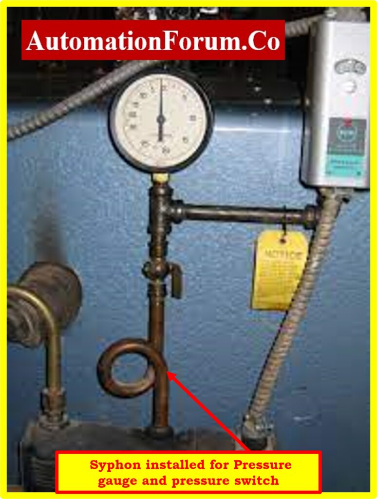
Where applicable, pressure gauges must have snubbers, syphons (for temperatures over 1000oC), and 3-way valve manifolds.
The air for pneumatic instruments must be dry and free of oil. Oil-free compressors built specifically for this need to supply the air. Air needs to be stored in the receiver after drying. Pressure gauges must be installed after the pressure reducer and on each supply line.
The proper level (height) between the tapping point, transmitter, and detecting element must be maintained.
The apparatus must remain in its standard alignment (level, perpendicular, front and back).
In order to prevent any time lag, connection must be kept close to the tapping point or detecting element whenever possible.
In order to prevent damage from metal waste, etc., orifice plates and control valves must only be installed on process piping after the process piping has been thoroughly cleaned.
The installation instructions provided by the individual instrument manufacturer may be consulted for further information as necessary.
The drain pipes must end in a shared closed header, which must then be linked to the plant’s open drain.
Before being used on site, each pipe’s material for the impulse must be identified. Coloring must be done for this purpose as soon as possible following receipt for identification.
After the installation, perform calibration and testing of the C&I equipment to verify its accuracy and functionality. Follow the manufacturer’s instructions for calibration procedures or consult a qualified technician if needed.
Maintain detailed documentation of the installation process, including drawings, diagrams, and records of any changes or modifications made. Clearly label the equipment, cables, and connections for easy identification and troubleshooting in the future.
Ensure that the installation complies with all relevant regulations, standards, and codes, such as electrical, safety, and environmental regulations.


