- Best P&ID Software Tools for Process Engineers in 2025
- 1. AutoCAD P&ID (Autodesk)
- 2. EdrawMax
- 3. Lucidchart
- 4. SmartDraw
- 5. Visual Paradigm
- 6. PROCAD P&ID
- 7. SolidPlant 3D
- 8. SmartPlant P&ID (Hexagon PPM)
- 9. AVEVA Diagrams (formerly AVEVA P&ID)
- 10. MicroStation P&ID (Bentley Systems)
- 11. DEXPI-Compliant Tools (e.g., COMOS by Siemens)
- Comparison table of top P&ID software tools for 2025
- Official Website & Download Links
- Standards Related to P&ID Software and Design
- What is the best software to draw P&ID?
- Can SolidWorks do P&ID drawings?
- How to create a P&ID drawing?
- Can I draw P&ID in AutoCAD?
- Can I draw P&ID in Revit?
- Which AutoCAD is best for piping?
- Is Revit good for piping?
- Is AutoCAD Plant 3D better than AutoCAD LT?
Piping and Instrumentation Diagrams (P&IDs) are very important in industrial engineering because they show how processes run, how control instrumentation works, and how equipment is set up. These diagrams are very useful for designing, operating, analyzing safety, and planning maintenance for plants that process oil and gas, chemicals, power, and water.
Making P&IDs by hand is boring and easy to mess up. Luckily, new P&ID software solutions make this job easier by having smart sketching functions, symbol libraries, tools for working together, and the ability to work with 3D design software.
This is an in-depth description to the 11 best P&ID software platforms, each of which has its own set of features for professionals, project engineers, and EPC teams.
Best P&ID Software Tools for Process Engineers in 2025
Efficiently Create Piping and Instrumentation Diagrams for Industrial Systems
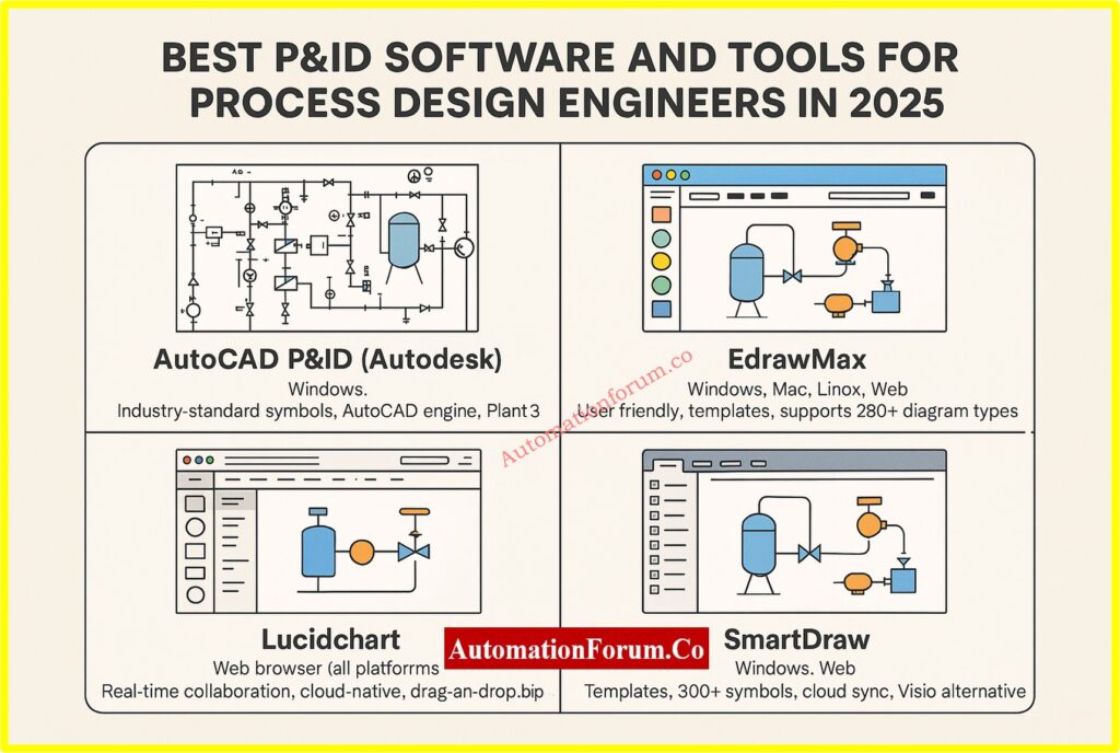
1. AutoCAD P&ID (Autodesk)
Autodesk created AutoCAD P&ID, a specific tool for AutoCAD that allows you design P&ID diagrams. It uses the powerful AutoCAD engine to offer features that engineers trust for accuracy, documentation, and compliance.
Features:
- Symbol libraries that are standard in the industry (ISA, ISO/DIN)
- Tagging, annotating, and relating data to components is easy.
- Integration with AutoCAD Plant 3D to keep models consistent
Pros:
- Accuracy in drafting that is up to professional standards
- The familiar AutoCAD interface makes it easier for experienced users to understand.
- Makes an instrument index and a bill of materials on its own
- Used by engineering firms and EPCs all over the world
Cons:
- Needs strong hardware and expertise with CAD
- Cloud collaboration isn’t as easy to use as SaaS technologies.
- Licensing costs a lot for small businesses.
Instrumentation Abbreviations in P&IDs List: Instrument Abbreviations used in P&ID Diagrams
2. EdrawMax
EdrawMax is excellent for making quick drawings and professional-looking diagrams without having to know how to use CAD. It has a drag-and-drop editor and works in the cloud.
Features:
- More than 10,000 templates and symbols that are standard in the industry
- AI-powered diagram-making tools (Pro version)
- Supports exporting to Visio, PDF, PNG, SVG, and other file types
- Dropbox and Google Drive can both be used with cloud storage.
Pros:
- Works on Windows, Mac, Linux, and the Web
- Good for exercising, writing, and talking to people visually
- Allows for collaborative editing and team workspaces
- Lifetime license at a low cost
Cons:
- Not good for advanced modeling of engineering data
- Not much automation for engineering logic and requirements.
Key P&ID Terminology Demystified Fast: Common Terms Used to describe P&ID Drawings
3. Lucidchart
Lucidchart is a visual diagramming tool that works in your browser. It’s noted for being easy to use and for letting people work together in real time. It isn’t made just for industrial engineering, but it works well for training diagrams, early drafts, and high-level process visualization.
Lucidchart is quite helpful for cross-functional teams, where engineers, operators, and stakeholders all need to work together at the same time.
Features:
- Standard P&ID shapes that you may drag and drop
- Editing and commenting in real time for group work
- Works with Google Workspace, Microsoft 365, Confluence, and Slack
- Works completely in the browser. You don’t need to download it.
Pros:
- Very easy for non-technical workers to use
- Great for initial planning and presentations
- Cloud-based with options for saving and sharing
Cons:
- Doesn’t have automated checks for technical specs or engineering design validation
- There is no desktop version that works offline.
- Not great for P&ID documentation for heavy-duty plants
Common P&ID Symbols Reference Chart: Common P&ID symbols used in Developing Instrumentation Diagrams
4. SmartDraw
SmartDraw is a strong diagramming tool that maintains a good balance between being easy to use and being able to do professional work. It has symbol sets for pipelines, instrumentation, pumps, valves, and sensors that are specific to each industry. This makes it perfect for documenting processes for medium-sized companies.
Features:
- More than 300 technical symbols for HVAC and P&ID diagrams
- Smart formatting for space and alignment
- Microsoft Office and Google Workspace work together.
- You can have it as a desktop or web version.
Pros:
- Not as complicated as CAD tools, but still strong
- Good for making visuals for mid-level reports and documents
- Includes templates and the ability to automatically arrange diagrams
Cons:
- Not made for modeling plants in 3D or specs in real time
- Not compatible with Mac or Linux desktops
Standard P&ID Symbols Explained Simply: P & ID Symbols
5. Visual Paradigm
Visual Paradigm is mostly used for modeling software and system architecture, but it also has great diagramming tools that help with process design, such P&IDs. It’s perfect for hybrid workflows that combine industrial process flows with system logic (UML, BPMN, SysML).
Features:
- Support for UML, BPMN, ERD, and P&ID at one place
- Collaboration in real time
- Built-in version control and job management
- You can get to it online and offline.
Pros:
- Great for teams that work on both software and processes
- Licensing models that are quite flexible
- Good for both business and school teams
Cons:
- The interface may be too much for new users.
- P&ID features are not as strong as those of dedicated piping software.
Piping & Instrumentation Diagram Documentation Overview: Piping & Instrumentation Diagram (P&ID)
6. PROCAD P&ID
PROCAD P&ID is a CAD program that was created just for creating process and pipe diagrams. It was made particularly for businesses like petrochemicals, water treatment, and refineries. It has rich symbol libraries, automation, and validation tools.
Features:
- Full libraries for valves, pipes, tools, and more.
- Design approach based on projects with automatic tagging and line numbering
- Onboarding help and tutorials
- Allows for interface with other PROCAD products, such as DESIGNER and 3DSMART.
Pros:
- Tools for drafting and documenting that are quite thorough
- Library of symbols that meets ISA standards
- Used by professional EPCs and design consultants
Cons:
- Only works on Windows
- Better for experienced engineers than beginners
How to Read P&ID Diagrams: Reading and Interpreting of Piping and Instrumentation Diagrams
7. SolidPlant 3D
SolidWorks is the base for SolidPlant 3D, which is made for engineers who need both 2D and 3D tools. It lets people make P&ID diagrams and then quickly turn them into detailed 3D layouts using real-world parts.
Great for plant, piping, and mechanical designers who work on big industrial projects.
Features:
- 3D library of tanks, pipes, valves, pumps, and more.
- Design based on rules and finding clashes
- Works in the SolidWorks program
- Makes BOMs, ISO drawings, and spec sheets.
Pros:
- Streamlined the procedure from 2D to 3D
- Automating things cuts down on design mistakes
- Works with most EPC and design-build workflows
Cons:
- Needs a license for SolidWorks
- Training and onboarding are necessary for complicated features.
8. SmartPlant P&ID (Hexagon PPM)
SmartPlant P&ID, which is now part of Hexagon’s Intergraph Smart® package, is a very smart P&ID program that follows rules. It was made for big industrial projects that need to be very accurate, follow the rules, and work with plant design systems at the enterprise level.
Features:
- Rule-based design to automatically enforce project standards
- Linking dynamic data across fields (electrical, instrumentation, process)
- Works perfectly with Smart 3D, Smart Electrical, and Smart Instrumentation
- Makes audit trails and validation reports to make sure engineering is sound
Pros:
- automating validation reduces down on errors and rework done by hand
- Good for the FEED and detailed design stages
- Makes sure that process schematics and asset information are the same
- Supported by Hexagon’s ecosystem
Cons:
- Needs a lot of training and setup
- The costs of licensing and infrastructure are considerable.
- Better for big businesses than tiny ones
9. AVEVA Diagrams (formerly AVEVA P&ID)
AVEVA Diagrams is a professional-grade P&ID tool that works with AVEVA’s comprehensive digital engineering and operations platform. EPCs often utilize it to create process systems and make sure that P&ID data is the same across all engineering fields.
Features:
- Integration with AVEVA E3D, Instrumentation, and Electrical in both directions
- Helps with smart item tagging and working together across disciplines
- Works with AVEVA Engineering to manage all of the plant’s data.
Pros:
- Excellent for EPC operations that involve more than one discipline
- Brings together process information for later use
- Encourages design uniformity and keeping track of versions
- Ready to work with 3D design and digital twin settings
Cons:
- Needs the AVEVA environment to work best
- More difficult to set up for P&ID needs that are not part of a larger system
10. MicroStation P&ID (Bentley Systems)
The MicroStation P&ID module from Bentley is part of its OpenPlant suite, which is made for businesses that need to be able to deal with both 2D and 3D models. It works with both ISO and ANSI standards and is utilized in public infrastructure, utilities, and energy.
Features:
- Works with OpenPlant Modeler and ProjectWise
- Rules engine that can be changed to check specs
- Support for common file types including DWG, DGN, and IFC
Pros:
- Works well with BIM, GIS, and infrastructure tools
- Good for projects that involve both plant and civil engineering
- Powerful tools for tracking changes and reusing data
Cons:
- More complicated for people who don’t use Bentley products
- Might be too much for simple or minor P&ID needs,
P&ID Basics for Beginners Guide: Basics of Piping and Instrumentation Diagrams (P&IDs)
11. DEXPI-Compliant Tools (e.g., COMOS by Siemens)
Siemens’ COMOS has P&ID features that meet the DEXPI (Data Exchange in the Process Industry) standards. COMOS is a plant engineering platform that combines engineering, operation, and maintenance into one database. P&ID is merely one layer of this database.
Features:
- Digital thread from design ideas to running the business
- Real-time consistency across 3D models, P&ID, and instrumentation
- Advanced tracking of changes and control of revisions
- Allows the transfer of smart P&IDs to DCS/PLC systems
Pros:
- Helps with workflows for Industry 4.0 and digital twins
- Companies who want to control the entire lifecycle prefer this.
- Working with Siemens PCS 7 and automation tools
Cons:
- Costly and hard to learn
- Mostly utilized by big companies or in important fields
Refer the below link for theP&ID Checklist for Instrumentation Design Engineer
Comparison table of top P&ID software tools for 2025
| S.No | Software Tool | Ideal For | Platform | Key Strength |
| 1 | AutoCAD P&ID (Autodesk) | Large engineering projects, detailed CAD drafting | Windows | Industry-standard symbols, AutoCAD engine, Plant 3D integration |
| 2 | EdrawMax | Students, beginners, educators | Windows, Mac, Linux, Web | User-friendly, templates, supports 280+ diagram types |
| 3 | Lucidchart | Team collaboration, non-technical users | Web browser (all platforms) | Real-time collaboration, cloud-native, drag-and-drop simplicity |
| 4 | SmartDraw | Mid-level professionals, Windows users | Windows, Web | Templates, 300+ symbols, cloud sync, Visio alternative |
| 5 | Visual Paradigm | Hybrid teams (software + process), educators | Windows, Mac, Linux, Web | UML + BPMN + P&ID support, version control, task tracking |
| 6 | PROCAD P&ID | EPCs, process engineers, oil & gas, water treatment | Windows | Auto-tagging, ISA-compliant symbols, integration with PROCAD tools |
| 7 | SolidPlant 3D | Large-scale 3D plant modeling inside SolidWorks | Windows (SolidWorks add-on) | 2D-to-3D sync, spec-driven libraries, ideal for plant design |
| 8 | SmartPlant P&ID | Enterprise-scale EPC projects | Windows | Rule-based design, Smart suite integration, engineering validation |
| 9 | AVEVA Diagrams | EPC workflows and digital twin integration | Windows | Syncs with AVEVA E3D, central database, spec management |
| 10 | MicroStation P&ID | Infrastructure + plant projects | Windows | OpenPlant integration, DWG/DGN/IFC support, spec validation |
| 11 | COMOS (Siemens) | Full lifecycle engineering, digital twin applications | Windows | DEXPI compliant, Siemens PCS 7 integration, real-time plant data sync |
Official Website & Download Links
| S.No | Software Tool | Official Website / Download Link |
| 1 | AutoCAD P&ID | https://www.autodesk.com/products/autocad/overview |
| 2 | EdrawMax | https://edrawmax.wondershare.com |
| 3 | Lucidchart | https://www.lucidchart.com |
| 4 | SmartDraw | https://www.smartdraw.com |
| 5 | Visual Paradigm | https://www.visual-paradigm.com |
| 6 | PROCAD P&ID | https://www.procad.com/products/pid |
| 7 | SolidPlant 3D | https://www.solidplant3d.com |
| 8 | SmartPlant P&ID | https://hexagonppm.com |
| 9 | AVEVA Diagrams | https://www.aveva.com |
| 10 | MicroStation P&ID | https://www.bentley.com |
| 11 | COMOS (Siemens) | https://www.siemens.com/comos |
Understand What a P&ID Means: What is P&ID and how to read the P&ID?
P&ID Legends and Symbol Meanings: P&ID legends
Standards Related to P&ID Software and Design
| S.No | Standard Name | Description |
| 1 | ISA S5.1 | Instrumentation symbols and identification (standard P&ID symbols, tagging conventions) |
| 2 | ISO 10628 | International standard for diagrams used in chemical and petrochemical industries |
| 3 | ANSI/ISA-5.1-2009 | Updated version of ISA S5.1 for instrumentation symbols |
| 4 | PIP PIC001 | Process Industry Practices for standard P&ID development and documentation |
| 5 | DIN 28004 | German standard for graphical representation in process engineering |
| 6 | ISO 14617 | Global symbol standard for diagrams in process, power, and other industries |
| 7 | DEXPI Standard | Data Exchange in the Process Industry for exchanging P&ID and plant design information |
The size of your project, the experience of your team, and your unique workflow needs will all influence the P&ID software you choose:
- Want a tool that is easy to use and doesn’t cost much? EdrawMax is a great place to start.
- Need advanced control over drafting and specs? Choose either AutoCAD P&ID or PROCAD.
- Looking for an online tool that lets you work with others? SmartDraw or Lucidchart are the best.
- Are you working in 3D? For complete plant modeling, SolidPlant 3D is the best choice.
Buying the correct P&ID software makes ensuring that designs are consistent, saves time, and increases the chances of project success throughout the whole engineering lifecycle.
What is the best software to draw P&ID?
For professional industrial-grade P&IDs, AutoCAD Plant 3D (AutoCAD P&ID) is widely regarded as the top choice, offering built‑in industry‑standard symbol libraries and 2D/3D integration.
Can SolidWorks do P&ID drawings?
Yes. SolidWorks P&ID, part of the SolidWorks Utilities, uses a structured XML-based format (.xml) to define equipment, piping, and instrumentation for routing and downstream assembly creation.
How to create a P&ID drawing?
Can I draw P&ID in AutoCAD?
Absolutely. you can draw P&IDs using AutoCAD Plant 3D, which is included with standard AutoCAD subscriptions, offering symbol libraries, drafting tools, and error checking specific to P&ID workflows
Can I draw P&ID in Revit?
Revit supports P&ID workflows via the Revit P&ID Modeler, which enables efficient piping design and annotation using standard P&ID conventions .
Which AutoCAD is best for piping?
AutoCAD Plant 3D, as a specialized toolset included with AutoCAD, is the best choice for piping and instrumentation design due to its symbolic libraries, specification-driven piping tools, and integration with 3D plant models .
Is Revit good for piping?
Revit, with the P&ID Modeler plug-in, supports schematic design and documentation for piping systems. However, it’s best suited for building services and HVAC rather than heavy industrial piping applications.
Is AutoCAD Plant 3D better than AutoCAD LT?
Yes. AutoCAD Plant 3D includes the Plant 3D toolset for advanced piping and instrumentation needs (like symbol libraries and 3D modeling), while AutoCAD LT offers only basic 2D drafting, missing specialized P&ID features.