In this article, we will see how to read and interpret P&ID.
How to read the Piping and Instrumentation Diagram?
The key for understanding Piping and instrumentation diagrams (P&IDs) is
- We must be familiar with every ISA standard P&ID instrument symbol and standard letter code of process plant instruments and equipment.
- Try to read some (P&IDs) Piping and instrumentation diagrams it becomes easy to read, trace, visualize and understand P&ID drawings.
- It is always preferred for project engineers to go through the P&ID symbols repeatedly.
Let us see about reading the P&ID
Consider the tag number FT 304.
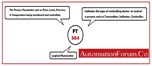
- The first letter F in the above tag number FT 304 indicates the process parameter that is being monitored and controlled. The process parameters such as Flow, Level, Pressure, & Temperature.
- The Second letter T in the above tag number FT 304 indicates the type of controlling device used to control a process such as a Transmitter, Indicator, Controller, and so on.
- The number 304 in the above tag number FT 304 indicates a logical numerator.
What is a Piping and Instrumentation Diagram?
- Piping and Instrumentation Diagram in short is abbreviated as P&ID.
- P&ID is defined as the diagrammatic representation of a process plant.
- It is the most commonly used document in the engineering field.
- It is a fundamental engineering document that serves various purposes
- This describes the piping and related components of a physical process flow along with machinery equipment and instrumentation.
- This P&ID is similar to the process flow diagram.
- It is also known as the Process Engineering Flow Scheme (PEFS).
What do the Tag numbers on a P&ID mean?

- Tag numbers on a P&ID are a series of letters followed by numbers that are used to identify a device type and its function being used for a particular process or a control loop.
- The device tag in P&ID is represented by a circle followed by tag numbers such as FV304.
- The P&ID diagram tells us where the device is located exactly.
- The presence or absence of a line inside a circle indicates the device’s location it may be in the field or the control room.
- No Line inside a circle indicates that the instrument is located near the operator in the process field.
- A solid Line inside a circle indicates that the instrument is located in a control room which can be easily accessible by the operator.
- The dotted line inside a circle indicates that the instrument cannot be accessed directly.
- The connection of an instrument to the control system and identification of devices is represented by Symbols, circles, and lines
- The piping and connection lines on P&ID also tell about the instrument.

- A Dotted line A indicates an electrical connection.
- A Solid line B indicates an interconnection via pipe work.
- The Solid line C with a cross mark indicates a pneumatic connection.
How to Read and Interpret the P&ID?

- The flow transmitter FT 304 is a field-mounted flow transmitter connected to a flow indicator and controller through an electrical connection.
- The flow indicator and controller FIC 304 is a control room-mounted instrument.
- A square root extraction of the input signal is given to the flow indicator and controller FIC 304 as part of the functionality.
- Here the flow is in proportion to the square root of DP that is measured by flow transmitter FT 304.
- The square root must be extracted to make the flow and DP proportional to each other.
- The flow indicator and controller FIC 304 produce an electrical output and are given to a field-mounted current to a pneumatic (I-P) converter.
- The current to pneumatic (I-P) converter TY 304 produces a pneumatic signal (3-15PSI) as an output signal and is sent to the control valve connected to it.
- TT 304 is the temperature transmitter and TIC 304 is the temperature indicator and controller to measure and control the temperature.
- TIC 304 is a temperature indicator and controller output is given to a data link or through internal software represented by lines with bubbles to the flow indicator and controller FIC 304as a set point.
- A typical on and off valve YIC 304is controlled by a solenoid valve fixed with a limit switch ZSH & ZSL.
- ZSH indicates the open position and ZSL indicates the closed position of the valve.
- Each input and output signal are cabled to the Programming Logic controller to make the operator accessible, indicated as a diamond in a square with a continuous horizontal line.
How to understand the P&ID sheet?

The P&ID Sheet is divided into different areas.
1. Revision history:
- The revision history table in the P&ID sheet contains information on the revision number, Revision Description, and details of authorities such as prepared checked, and approved.
- The first sheet is named revision 0 followed by 1,2..3 …
- This revision history table must be kept updated periodically during every change made in the process area.
2. Title block:
- The title block is the first thing that must be noted before reading the P&ID sheet.
- This title block indicates the section of the plant P&ID
- This title block includes
- Title of Project: The name of the new or existing project.
- Client name: Name of the client such as factory name
- Consultant name: Name of project developer
3. Drawing number and revision:
- This drawing number is the most important area of the P&ID sheet.
- It is a numerical text that indicates the number of the document.
- This drawing number helps us to track the P&ID sheet of the required part projects in the process industry.