In this article, we have shown some symbols used in P&ID.
- There are many symbols that are used in P&ID piping and Instrumentation diagrams or drawings.
- The piping and instrumentation diagrams P&ID has a library of symbols.
- This set of symbols helps us in developing piping and instrumentation diagrams.
- When we see this document or drawing we can easily analyze the complex process structure.
Here are the lists of common P&ID symbols of process equipment valves, flow meters, and piping line connections.
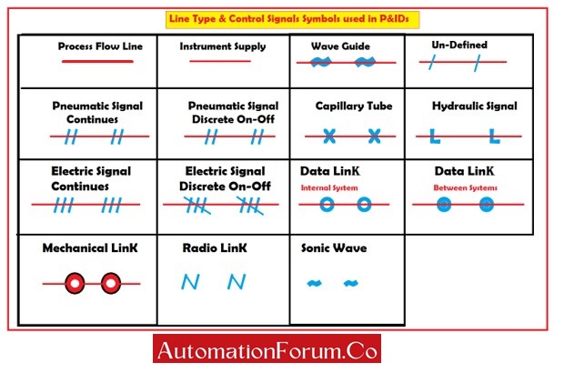
1. Line Type & Control Signals Symbols Used in P&IDs:
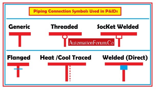
2. Piping Connection Symbols Used in P&IDs:
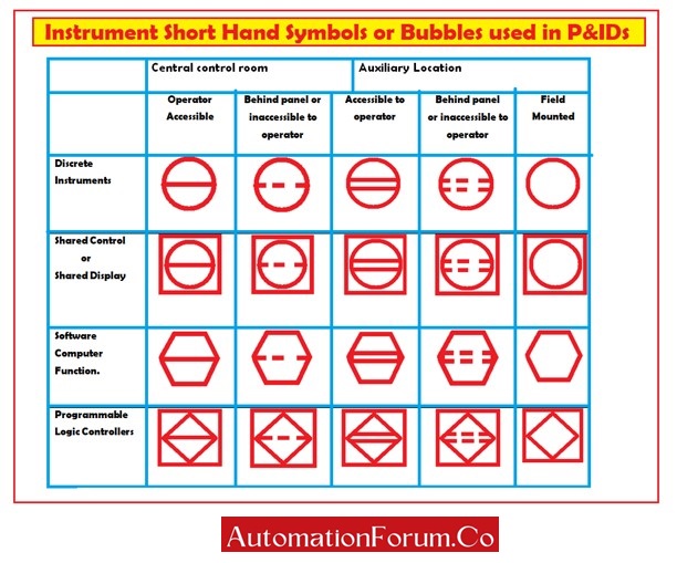
3. Instrument Short-Hand Symbols or Bubbles Used in P&IDs:
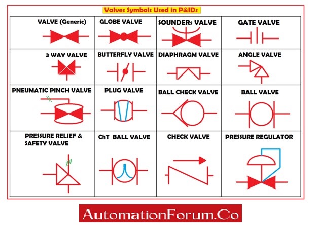
4. Valves Symbols Used in P&IDs:
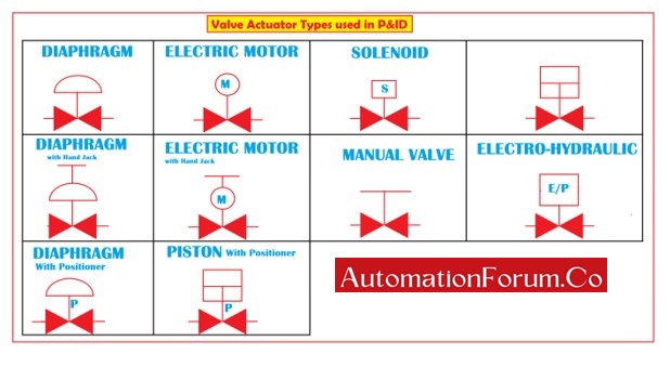
5. Valve Actuator Types Used in P&IDs:
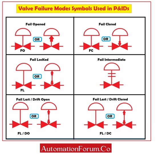
6. Valve Failure Modes Symbols Used in P&IDs:
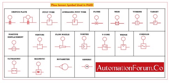
7. Flow Sensors Symbols Used in P&IDs:
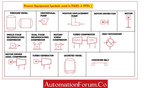
8. Process Equipment Symbols Used in P&IDs & PFDs:
Some Important Terms:
1. Wave Guide:
A waveguide governs or controls a wave.
It is known as an electromagnetic feed line.
This restricts energy transmission to one direction with minimum energy loss without any physical obstruction of a waveguide.
This waveguide is used in microwave communications, broadcasting, and radar installations.
2. Capillary tube:
The flow is against gravity by capillary action.
These capillary tubes are very thin.
Rigid material such as plastic or glass is used for making capillary tubes.Globe Valve
A globe valve is a type of valve used for controlling the flow of fluid in the pipeline.
This valve consists of a movable plug element and a stationary ring seat in a spherical body.
3. Butterfly Valve:
A butterfly valve is a type of valve used to control the flow rate of the flowing fluid through a rotating disk as a closing and opening mechanism.
This butterfly valve has a quarter turn valve for about 90 Degrees of rotation the valve gets fully opened or fully closed when the disc is rotated a quarter turn.
These valves allow for quick operation and are cheaper than other valves.
4. Ball Valve:
A ball valve is another type of flow control valve which uses a hollow perforated and pivoting ball to control liquid flowing through it.
This valve gets opened when the ball hole is in line with the flow inlet to allow the flow of fluid.
This valve gets closed when the ball hole is pivoted to 90 Degrees by the valve handle to block the flow.
The shut position of the valve is 1/4 turn.
The direction of valve operation may be either clockwise or anti-clockwise.
5. Angle Valve:
It is simply called a stop valve.
In an angle valve, the inlet and outlet ports are perpendicular to each other.
It is considered a manual valve because this valve controls or prevents fluid flow.
6. Diaphragm Valve:
These types of valves are called diaphragm valves because they consist of a thin, flexible membrane for controlling the flow by opening and closing the valve.
These types of valves consist of two or more ports.
7. Gate Valve:
Gate valves are commonly known as sluice valves.
This valve opens by lifting a barrier or gate out from the fluid.
Gate valves shut off the fluid flow rather than regulating fluid flow
Installation of these gate valves requires very little space along the pipe axis.
These gate valves do not have any obstruction in the flow path when fully opened.
8. Plug Valve:
These plug valves have the plug cylindrical or conically tapered in shape.
The flow is controlled by the plugs rotated inside the valve body.
The plugs consist of one or more hollow passages going sideways through the plug so that fluid can flow through the plug when the valve is fully opened.
These plug valves are simple in construction.
When the plug has conically tapered the stem and handle are normally fixed at the larger diameter side of the plug.
9. Pneumatic Pinch Valve:
The pneumatic pinch valve functions like a tap.
This type of valve has an on and off function to shut off, allow, or control the fluid flow.
These pinch valves are generally used when the flowing media is required to be completely isolated from the valve’s internal part.
10. Three-way Valve:
A three-way valve is a valve having three ports called openings.
The connection between these three ports has a spherical metal ball with a cylindrical bore called an opening to allow and control the flow of media.
There is another mechanism to rotate the ball that directs the flow from one point to another.
These 3-way valves are used for diverting and mixing fluids rather than using multiple 2-way valves.
These valves are cost-effective.
These valves can mix fluids from more than one inlet port.
11. Pressure Regulator:
A pressure regulator is another type of valve for controlling the fluid pressure to the desired value.
These use negative feedback from the controlled pressure.
These pressure regulators are used only for gases and liquids but not for solids.
The pressure regulator consists of two types one is a pressure reduction regulator and the other is the back-pressure regulator.
This is an integral device with a pressure setting, a restrictor along with a sensor.
12. Check Valve:
A check valve is commonly known as a one-way valve.
This is a unidirectional valve because this valve allows the flow in only one direction.
The primary function of a check valve is to prevent the backflow of fluid in the system.
These check valves are cheap.
13. Pressure relief and safety valve:
This valve acts as a fail-safe valve.
This valve automatically releases the pressure when it exceeds the above-designed preset valve.
It is also called a pressure relief valve.
The two basic types are the diaphragm type safety valve and piston type safety valve.
14. Solenoid:
Solenoid valves are a type of final control element.
It is used to allow fluid flow when the coil gets electrically energized or to shut off the fluid flow or when the coil gets de-energized electrically.
15. Piston:
The piston valve is a device for controlling the fluid motion in a pipe or tube through the linear motion of a piston within a cylinder chamber.
This valve contains a piston rod that blocks the output when the valve is pressurized and a volume of air behind the piston.
When the pressure gets released the piston is pushed back by the force of the input pressure.
16. Electric motor:
An electric motor is a device that converts electrical energy into proportional rotating mechanical energy.
These electric motors are operated by the interaction between the magnetic field of the electric motor and the winding current to generate force in the form of torque applied on the motor’s shaft.
17. Electro-hydraulicservo valves:
It is an electrically operated valve that controls how hydraulic fluid is sent to an actuator.
These valves provide precise control of the position.
These electrohydraulic servo valves consist of single-stage, Two-stage, and three-stage servo valves.
A single-stageelectro-hydraulic servo valve uses a torque motor to position a spool valve directly.
Two-stage electro-hydraulic servo valves use flapper, jet pipe, or deflector jet valves as hydraulic amplifiers to position the spool valve.
The three-stage electro-hydraulic servo valves use an intermediate stage spool valve for positioning a larger third stage spool valve.
18. Fail open:
The valve opens upon the failure or loss of an energy signal called Fail Open (FO).
19. Fail close:
The valve closes upon the failure or loss of an energy signal called Fail Close (FC).
20. Fail locked:
In an event of power failure, the valve remains in the locked position. The fail lock is known as fail secure.
21. Fail last drift open or closed:
The failure last in a control valve means when the valve loses its driving force and the valve stem remains in its previous position.
These valves may be locked at their previous position afterthe failure of the air supply.
Control valves with fail last as a failsafe condition can be either fail last drift close or Fail last drift open
Due to leakages in the control valve, they may either go to the open position for FLDO or the closed position for FLDC.
22. Pressure Vessel:
A pressure vessel is a huge container that is designed for storing fluids such as gases or liquids at a pressure considerably different from the ambient pressure.
23. Centrifugal pump:
A centrifugal pump is a mechanical device that is designed for transferring fluid from one place to another place utilizing impellers.
The flowing fluid enters the rotating impeller along its axis and is cast out by the action of centrifugal force along its circumference through the vane tips impeller’s
24. Positive displacement pump:
A positive displacement pump lifts the fluid by surrounding it in a fixed volume and moving it mechanically through the system.
The action of the pump is cyclic and can be driven by pistons, screws, gears, rollers, diaphragms, or vanes.
25. Single-stage reciprocating compressor:
A single-stage reciprocating air compressor works using the force of a piston and pressure-sensitive valve.
This compressor is designed for only one cylinder to compress air with a single piston stroke.
In this compressor, the air is compressed only one time.
To compress the air, the cylinder is connected to a power supply to provide the required force.
26. Dual stage reciprocating compressor:
This dual-stage compressor is ideal for most demanding industrial applications.
These are much stronger than single-stage compressors and can handle large pressure and large capacity.
In this compressor, the air is compressed twice to raise the pressure.
This dual compression cycle makes the compressor more efficient.
This compressor compresses the air on both the up stroke and the down stroke of the piston.
27. Turbo generator:
A turbo generator is an auxiliary electric generator connected to a turbine shaft to generate electric power