- What is DP level?
- How is DP transmitter level calculated?
- How to calibrate DP type level transmitter?
- Purpose and Scope:
- Tools required for DP transmitter calibration:
- Safety
- Calibration Setup for DP type level transmitter
- Calibration procedure
- Example calibration
- Recording calibration
- Completion of calibration
- Specific Errors encountered after calibration
- Sample calibration report
What is DP level?
A differential pressure transmitter measures the pressure difference between the liquid and gaseous phases of a fluid inside a closed tank to calculate level. Differential Pressure (DP) Level Measurement outputs level based on pressure measurements and specific gravity. A widely used measurement method is DP Level, which has a wide range of applications. For accurate computations, crucial factors include the following:
- Dimensions of the tank (horizontal or vertical, shapes of various lids and bottoms, etc.)
- Specific medium density.
- Hydrostatic pressure.
How is DP transmitter level calculated?
Level (H) = DP / SG
In this instance, SG stands for the liquid’s specific gravity and DP for the measured differential pressure. To determine the level of a liquid, use this simple, tested principle.
How to calibrate DP type level transmitter?
Purpose and Scope:
The in-depth description of this procedure describes how to calibrate a level DP transmitter by making use of standards located in the process area.
Tools required for DP transmitter calibration:
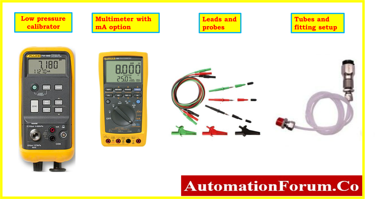
- Necessary hand tools.
- Standard low Pressure Calibrator.
- Standard Multimeter.
- Test leads and probes.
- Tubes and standard fittings
- Soft Cloth for cleaning.
Safety
- Please visit the provided link to understand more about fundamental safety, general guidelines, and calibrating operations in process industries.
Basic Safety and General Concerns for the Process Industry Calibration Process
- For the level control loop, request that the panel operator set the controller in manual mode, and for the ESD loop, set it to MOS.
- Find the level transmitter of the DP type that you want to calibrate. Make sure the DP type level transmitter is the correct one, and note and double-check any important details, like the Tag number (e.g., the manufacturer, model number, pressure range, etc.).
- Before calibrating the DP type level transmitter, depending on the system type, you might need to depressurize the impulse tubes of the system and the DP type level transmitter. Use the appropriate techniques to depressurize the system (e.g., vent the pressure by drain valve or isolate the both HP and LP process tapping valves of the DP type level transmitter).
- Close or disconnect the tubing that connects the DP level transmitter to the process. As a result, no fluid will seep out and the DP type level transmitter will be isolated from the process.
- Do not disconnect the DP type level transmitter’s power supply. Check any nearby junction boxes or marshalling panels close to the control room to see if the power supply is present at the source using an instrument loop diagram.
- Keep in mind that depending on the particular equipment and process location, this overall technique may need to be modified.
- When dealing with DP type level transmitters or other process equipment, always adhere to all manufacturer instructions and regional safety regulations.
- To avoid an unintended start, adhere to all applicable lockout/tagout protocols. Remember to keep the DP type level transmitter isolated from the process.
Calibration Setup for DP type level transmitter
- Electromagnetic interference and vibrations must not exist in the process region where the calibration equipment is placed. Also, the area needs to be well-ventilated and illuminated.
- Get all of the essential instruments and tools in one place.
- In the event that the operation involves a danger, you must ensure that the necessary flushing is carried out in order to completely eliminate the risk.
- Open the equalizing valve and close the transmitter manifold‘s LP and LP isolation valves.
- Drain the process fluid from both the HP and LP side legs by opening the drain valve in the impulse line on both sides.
- Clean the fittings and any remaining fluid in the transmitters after disconnecting the HP and LP side impulse lines from the transmitter manifold.
- Check the transmitter HP & LP pressure ports to make sure they are dry.
- The output of the low pressure calibrator should be linked to one end of the tube, and the high pressure side (HP) of the DP transmitter should be connected to the other end. Make sure the connections are tight and leak-free by inspecting them.
- The transmitter’s low-pressure side (LP) is always kept open to the surrounding atmosphere.
- Between the junction box and the DP type level transmitter, use probes and a lead to connect the multimeter (mA mode) in series with an analogue input loop.
- The HART field communicator should also be connected to the DP type level transmitter terminal if the transmitter is smart type.
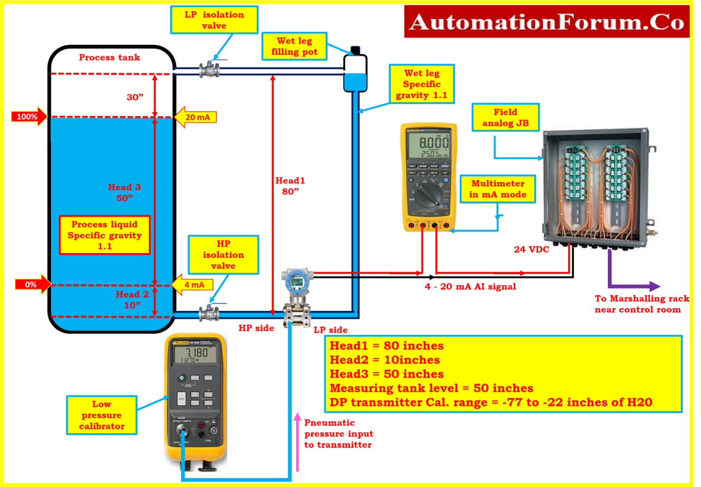
- The connections have been established and are currently being prepared for the calibration of the DP type level transmitter, as shown in the diagram.
Calibration procedure
- Check the tubing and wire connections of the DP type level transmitter for steadiness.
- Open the transmitter terminal cover and verify that the power supply is 24 VDC is present in the terminal.
- You can confirm a number of the parameters by referencing the instrument data sheet. Typical parameters are the tag number, specific gravity of the fluid, LRV, and URV.
- If it’s a smart transmitter, you may verify the parameters with a hart communicator.
- The LRV and URV can be estimated using the tank dimensions, fluid specific gravity, and transmitter HP and LP tapping positions.
- For example, if the transmitter is installed as indicated in the calibration setup picture above, the transmitter’s LRV and URV are determined as detailed below.
Example calibration
Head1 = 80 inches = Height of the LP side of the transmitter.(wet leg Filled with process fluid)
Head2 = 10 inches = 0% of Measuring range.
Head3 = 50 inches = Actual measuring range of the level.
Measuring tank level = 50 inches.
Specific gravity of the fluid = 1.1
DP transmitter Cal. range = -77 to -22 inches of H20
At zero percentage of level (for 4mA output)
DP = Phigh – Plow
= Head2 – Head1
= (1.1 X 10”) – (1.1 X 80”)
=11” – 88”
At 4 mA = -77”H2O
At 100 percentage of level (for 20mA output)
DP = Phigh – Plow
= (Head2 + Head3) – Head1
= [(1.1 X 10”) + (1.1 X 50”)] – (1.1 X 80”)
=11”+55”-88”
At 20 mA = -22”H2O
Cal. Range = -77 to -22”H2O(4 to 20mA)
- Configure the calibration range’s LRV as the transmitter’s 0% Lower Range Value (LRV).
- Set the calibration range’s upper range value (URV) for the transmitters’ span to 100%.
- Apply the LRV 0%, which equates to -70 inches of H2O, to the transmitter’s high pressure side by low pressure calibrator and its low pressure side, open side to the atmosphere.
- Check at the multimeter now; it should be showing 4mA.
- If the 4mA reading is not showing up on the display, find the zero adjustment on the DP type level transmitter and make the appropriate adjustments until the reading shows 4mA; alternatively, use the HART Communicator to make the necessary adjustments for the smart transmitter.
- It is always necessary to refer to the DP type level transmitter manufacturer’s maintenance instruction manual in order to find the zero and span adjustment.
- Adjust the ZERO adjustment option in the display or the zero adjustment potentiometer of the DP type level transmitter while keeping an eye on the multimeter’s 4mA reading. This is the LRV output of your transmitter.
- Apply pressure to the high pressure side of the transmitter to increase the reading to the 100% higher value (URV), which is -22 inches of water.
- Adjust the SPAN adjustment menu in the display or the SPAN adjustment potentiometer of the transmitter while maintaining focus on the 20mA reading on the multimeter. This is the URV output of your transmitter.
- The calibration process must be repeated as many times as required until the DP level transmitter is calibrated to the required tolerance.
- The calibration procedure may vary depending on the specific low pressure calibrator and DP level transmitter being utilized. Thus, before starting off, make sure you follow to the manufacturer guidelines.
Recording calibration
- Check the linearity of the DP level transmitter’s output at 0%, 25%, 50%, 75%, and 100% in both the upscale and downscale directions to ensure that it is generating the desired output values.
- Calibration is necessary if the output value does not fall within an acceptable range. If the output values have departed from the acceptable range once again, the DP level transmitter must be repaired or replaced.
- No additional calibration is needed for the DP level transmitter if all output values (+/- %) fall within acceptable boundaries.
- The blank calibration report’s as found/as left column should be filled in with the output data.
Completion of calibration
- Attach the calibration label to the DP transmitter once the calibration has been completed successfully.
- Clean the test equipment after calibration is finished, store it safely, and record the calibration information for later use.
- Remove the low pressure calibrators, DP level transmitter, and other calibration setup.
- The DP level transmitter connections need to be fixed back in the processing area. As well as flush the impulse lines and eliminate any airlock on the HP as well as LP side.
- You should also pour process fluid into the LP side wet leg using the wet leg pot. Verify to make sure the impulse lines do not contain any air locks.
- Verify the cleanliness of the workplace.
- De-isolate the equipment.
- Restore the dp level transmitter signal’s bypassed or inhibited signal to its initial level.
- Prior to commencing use, verify that the DP level transmitter is operating properly.
Specific Errors encountered after calibration
Refer to the link below for troubleshooting instructions if you encounter any issues after calibration when commissioning and lining up the DP level transmitter.
Instructions on how to troubleshoot the DP type of level transmitter
Sample calibration report
The image that follows shows how the DP level transmitter sample report was calibrated in a process area utilizing a low pressure calibrator and multimeter as the reference.

You may get the Excel document that was used to construct the DP transmitter calibration report by clicking the link below.