- What is the use of orifice plate assembly?
- Overview of Orifice Plates and Flow Measurement
- What is the purpose of installing a thermowell for the sensors?
- Role of RTD Thermowells in Temperature Measurement
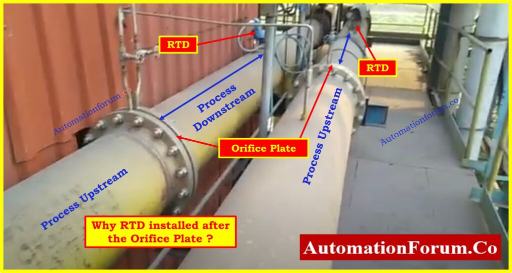
- Why RTD installed after the Orifice Plate ?
- AGA Standards and Guidelines on RTD Placement
- Spacing Requirements and Practical Limitations
- Technical Aspects: The Impact of Upstream vs. Downstream Placement
- Downstream Placement Benefits
- Upstream Placement and its Challenges
- Additional Factors affecting RTD Placement in Flow Systems
- Best Practices for RTD Installation around Orifice Plates
Temperature measurement is a critical component of flow measurement systems. RTD (Resistance Temperature Detector) sensors are widely used due to their accuracy and reliability in detecting temperature changes. In flow systems involving orifice plates, the placement of RTD sensors significantly impacts measurement accuracy.
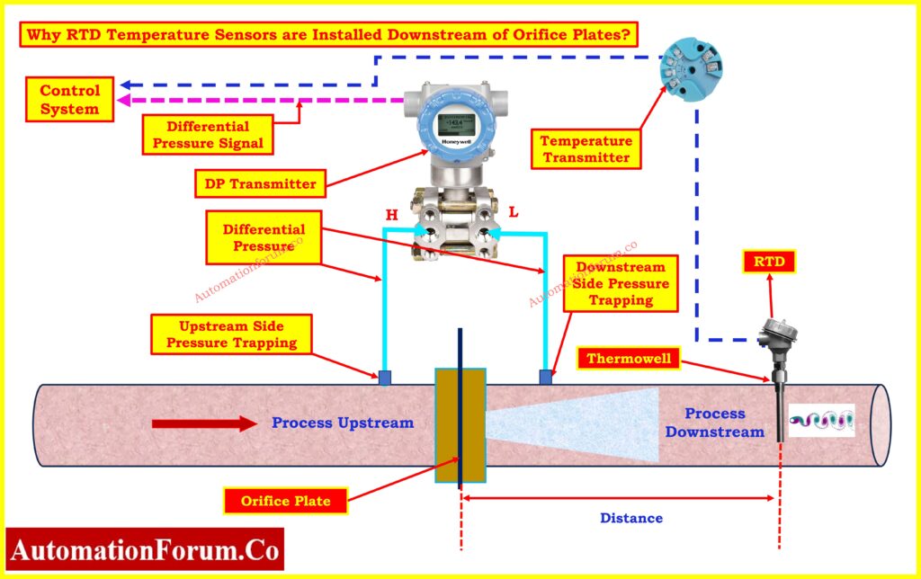
This article explores why RTD thermowells are typically installed downstream of orifice plates and the technical and industry-driven reasons for this practice.
What is the use of orifice plate assembly?
Overview of Orifice Plates and Flow Measurement
- Orifice plates are a type of differential pressure flow meter. They are positioned within pipes to restrict fluid flow, causing a pressure drop that correlates with flow rate.
- Accurate temperature measurements are crucial here because temperature fluctuations can influence fluid properties, thereby affecting the precision of the flow calculations.
- In flow measurement systems, the presence of turbulence can complicate the accuracy of readings.
- Since the orifice plate itself causes turbulence, minimizing any additional disturbances is essential to achieving reliable results.
Click here for Orifice Plate Flow and Pressure Drop Calculation Excel Tool.
What is the purpose of installing a thermowell for the sensors?
Role of RTD Thermowells in Temperature Measurement
- Thermowells house RTD sensors, protecting them from direct exposure to the fluid while allowing accurate temperature detection.
- They are essential in process environments, where conditions can be extreme.
- When positioning RTD thermowells, the objective is to ensure they do not disrupt the fluid flow in a way that could affect other instrumentation, such as the orifice plate.
Click here for RTD Commissioning Checklist
Why RTD installed after the Orifice Plate ?
RTD thermowells are generally placed downstream of orifice plates to prevent interference with the flow conditions around the plate.
The below points are the main reasons for this:
Turbulence and Flow Disturbance Mitigation
- The orifice plate causes pressure differentials and turbulence. If the thermowell is placed upstream or near the orifice plate, it could amplify this turbulence.
- The added disturbance can lead to inaccurate readings by generating additional, unpredictable pressure fluctuations.
- By placing the RTD downstream, the orifice plate’s readings remain stable, as the turbulence caused by the thermowell dissipates before it can affect flow measurement.
Von Kármán Vortex Shedding
- One of the most critical phenomena involved in RTD placement is von Kármán vortex shedding.
- This occurs when fluid flows around an object, like a thermowell, causing alternating low-pressure vortices to be shed on either side.
- This vortex “street” generates oscillating forces that can disrupt the flow.
- If the RTD thermowell is upstream of the orifice plate, these vortices will interfere with pressure measurement, causing fluctuations and potentially erroneous readings.
- By placing the RTD downstream, the vortex street doesn’t interfere with the orifice plate, as the disturbance has already passed.
- This positioning ensures that vortex shedding won’t reach the orifice plate, preserving the accuracy of flow measurement.
AGA Standards and Guidelines on RTD Placement
- The American Gas Association (AGA) has established guidelines for RTD placement around flow meters like orifice plates.
- According to the AGA, RTD sensors can be placed upstream of the orifice plate, but only if they are positioned at least three feet away from a flow conditioner.
- A flow conditioner helps to straighten the flow, removing turbulence and ensuring the fluid enters the orifice plate evenly.
- AGA standards permit upstream placement with the correct spacing and use of a flow conditioner because these measures ensure that the fluid’s behavior near the orifice plate remains predictable.
- However, these guidelines are often challenging to implement in practice, as spacing and flow conditioners aren’t always feasible, especially in compact setups.
Spacing Requirements and Practical Limitations
- The three-foot spacing requirement upstream of a flow conditioner is a minimum guideline; it ensures the vortices from the thermowell don’t interact with the orifice plate.
- In practice, however, providing this amount of space in many industrial installations is difficult. Limited space often makes downstream placement more practical and reliable, as it reduces the complexity of setup and avoids the need for additional equipment like flow conditioners.
Technical Aspects: The Impact of Upstream vs. Downstream Placement
While downstream placement of RTDs is preferred due to its simplicity and reliability, there are scenarios where upstream placement could be necessary. Let us look at both type of installation configurations:
Downstream Placement Benefits
Reduced Interference:
- The RTD thermowell downstream means any turbulence it causes has already been accounted for in the orifice plate’s readings. The impact on pressure measurement is minimized.
Easier Installation:
- Downstream placement does not require extensive spacing or flow conditioners, making it suitable for more compact systems.
Consistency with Flow Direction:
- The RTD is measuring the temperature in a location where the fluid’s behavior has settled post-orifice, ensuring that measurements are reflective of stable conditions.
Click here for RTD Tolerance Calculation
Upstream Placement and its Challenges
In some situations, upstream placement is used to measure the temperature before any pressure drop or flow disturbance.
However the below challenges include:
Spacing Requirements:
- As mentioned, upstream placement requires a minimum distance from a flow conditioner to ensure accurate readings.
Increased Setup Complexity:
- The need for flow conditioners and precise spacing makes this setup more complex and potentially costlier.
Higher Risk of Measurement Disturbances:
- Without adequate spacing, the RTD thermowell can cause vortices that interfere with the orifice plate, impacting the accuracy of both temperature and flow measurements.
Additional Factors affecting RTD Placement in Flow Systems
Several other factors influence the placement of RTD thermowells in flow measurement systems, including:
Fluid Velocity and Flow Profile
- High fluid velocity increases the intensity of vortex shedding, which can worsen if the RTD is upstream.
- This intensifies the need for downstream placement where the effects of shedding are less critical.
Pipe Diameter and Length
- The larger the pipe diameter, the more turbulent the flow, which may necessitate the use of flow conditioners.
- The available pipe length also affects the feasibility of downstream placement, as well as the ability to maintain necessary spacing in upstream configurations.
Click here for 8 Steps RTD Calibration Procedure
Fluid Type and Viscosity
- Viscous fluids exhibit different flow characteristics compared to gases or low-viscosity liquids.
- In these cases, RTD placement downstream is often more effective, as these fluids have a higher potential for turbulence.
System Layout and Accessibility
- The overall system design, including accessibility for maintenance and the presence of other instrumentation, will also dictate RTD placement.
- Downstream installations are often more accessible, as they allow for straightforward maintenance without disturbing the flow meter setup.
Best Practices for RTD Installation around Orifice Plates
- The most reliable practice for RTD thermowell placement in relation to orifice plates is downstream.
- This positioning mitigates issues related to turbulence and vortex shedding, which can cause inaccuracies in flow measurement.
- The AGA guidelines allow for upstream placement if certain conditions are met, but practical considerations often make downstream installation more feasible.
- For engineers and technicians involved in instrumentation, understanding these placement principles is essential for ensuring accurate, reliable flow and temperature measurements.
- By following best practices and adhering to industry standards, systems can be optimized for performance and longevity, minimizing the need for corrective measures or costly adjustments.
- Correct RTD placement is crucial for maintaining the accuracy of both temperature and flow measurements in systems involving orifice plates.
- By choosing downstream installation, engineers can ensure that turbulence and vortex effects do not interfere with measurement accuracy.
- Whether designing new systems or optimizing existing ones, adherence to these principles and standards will yield the most reliable results.
Click here for How to Calibrate RTD transmitter?