- Introduction on Instrument Failures Seen Most Frequently in Process. Plants
- Why Instrument Reliability Matters in Every Process Plant
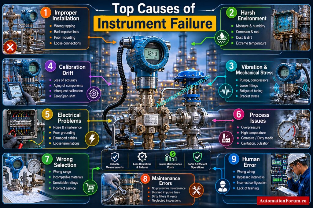
- Improper Instrument Installation
- Harsh Environmental Conditions
- Vibration and Mechanical Stress
- Calibration Drift
- Electrical Problems
- Process Related Problems
- Wrong Instrument Selection
- Poor Maintenance Practices
- Human Error
- Top 10 Instrument Failures Seen Most Frequently in Process Plants
- Real Industrial Failure Case Studies
- How to Reduce Instrument Failures by More Than 50 Percent
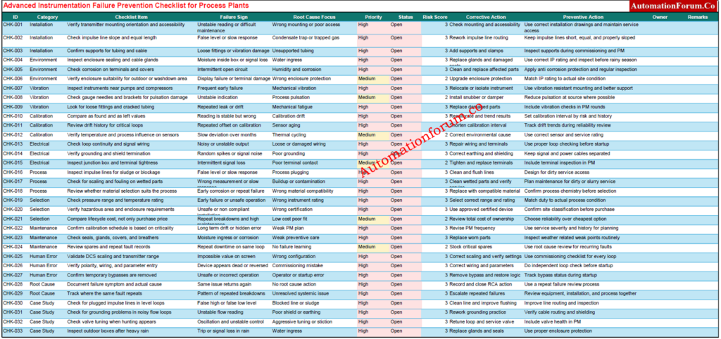
- Download : Advanced Instrumentation Failure Prevention Checklist for Process Plants
- FAQ on Instrument Failures on Process Industry
- Why do pressure transmitters fail in process plants?
- What causes calibration drift in industrial instruments?
- How does vibration damage industrial instrumentation?
- What is the most common instrument failure in industry?
- How can grounding problems affect 4 to 20 mA signals?
- Why do impulse lines get blocked in instrumentation systems?
- Why do instruments fail more during rainy seasons?
- How can wrong instrument selection reduce plant reliability?
- Why is loop checking important during commissioning?
- Can poor maintenance create repeat instrument failures?
- How does a control valve create process instability?
- How do plants reduce instrument failures quickly?
- Why do flow meters give unstable readings?
- What causes false level indication in tanks?
- Why does electrical noise affect instrumentation systems?
- Why do control valves start hunting?
- What causes moisture ingress in junction boxes?
- Why do pressure gauges fail near pumps?
- What are the signs of calibration drift?
- Why is preventive maintenance important for instrumentation?
- How does poor cable routing affect instrumentation signals?
- Why do transmitters fail repeatedly in the same location?
- What causes unstable DCS process values?
- Why is root cause analysis important in instrumentation?
- Conclusion: The Real Secret Behind Instrument Reliability
Introduction on Instrument Failures Seen Most Frequently in Process. Plants
Instrumentation is one of the most important parts of any process plant, yet it is also one of the most misunderstood. When an instrument fails, many people immediately blame the device itself. In reality, most problems begin much earlier, often during installation, selection, commissioning, or maintenance. A transmitter, valve, sensor, or analyzer may be perfectly capable of doing its job, but if the surrounding conditions are wrong, the final result will still be poor.
This is why industrial instrumentation troubleshooting matters so much. The goal is not only to replace a failed device. The real goal is to understand why it failed, remove the root cause, and stop the same problem from happening again.
Why Instrument Reliability Matters in Every Process Plant
Instrument reliability affects production, safety and cost
A single bad transmitter can create a false reading that disrupts a control loop. A blocked impulse line can create a false level indication. A drifting temperature sensor can affect product quality. A noisy loop can confuse the control system. In a plant, these issues do not stay small for long. They can spread into downtime, waste, unsafe operation, and expensive maintenance work.
Most failures are not random
Many plants treat instrument failure as an unpredictable event. That mindset is costly. In most cases, the same patterns repeat again and again. A device fails in one location because vibration is high. Another fails because moisture enters the enclosure. Another drifts because the service is severe and the calibration interval is too long. When these patterns are tracked properly, failure prevention becomes much easier.
Test Your Skills on Bently Nevada 3500 Troubleshooting: Troubleshooting Bently Nevada 3500 Series Vibration Monitoring System Quiz for Process Industries
Improper Instrument Installation
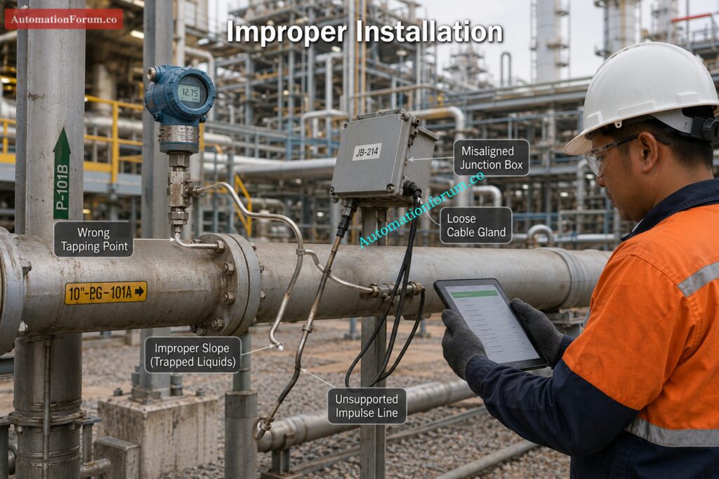
How Installation Mistakes Create Early Failures
A large number of field problems begin with installation errors. Even a high quality instrument can give poor performance if it is mounted in the wrong way or connected poorly. Wrong orientation, poor routing, unsupported tubing, and bad tapping points can all lead to unstable readings and early failure.
Common Installation Errors in the Field
Some of the most common issues include excessive vibration at the mounting point, impulse lines with high points or low points that trap gas or liquid, poor cable glanding, missing supports, no drain or vent arrangement, and poor access for calibration and maintenance. These may look small during commissioning, but over time they become serious reliability problems.
Why installation problems are often overlooked
Field teams often blame the instrument because the symptoms appear at the device. But the actual cause is often the surrounding installation. For example, a differential pressure transmitter on a steam line may drift because condensate is trapped in the impulse tubing. The transmitter is not the true problem. The installation is.
How to Prevent Installation Related Failures
Good installation begins with vendor drawings and proper mechanical practice. Impulse lines should be short, equal, and properly sloped. Supports should be added where needed. Mounting should be suitable for the service and easy to maintain. Loop checking should be part of commissioning, not something done later when the plant is already struggling. In simple terms, installation should be treated as part of the instrument, not as something separate from it.
Refer the below link to Solve Tough Solenoid Valve Failures Like Senior Engineers
https://automationforum.co/solenoid-valve-troubleshooting-quiz-instrumentation/
Harsh Environmental Conditions
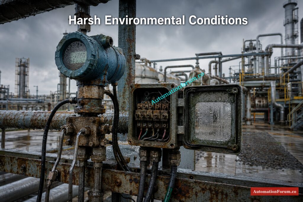
How Heat Moisture Dust and Corrosion Damage Instruments
The environment can destroy reliability faster than almost any other factor. Instruments exposed to high temperature, humidity, chemical vapors, dust, ultraviolet light, and water ingress will age much faster than expected. Seals break down, terminals corrode, enclosures weaken, and electronic parts begin to fail.
Why Enclosure Protection and IP Rating Matter
An enclosure that works fine in a clean panel room may fail completely outdoors or in a washdown area. This is why the protection level must match the real site condition. The enclosure rating should not be chosen only from the datasheet. It must suit the actual environment.
Common Signs of Environmental Damage
Common signs include corroded terminals, intermittent open circuits, eroded cable insulation, display failure, moisture inside the enclosure, and unstable sensor readings. In rainy seasons, these problems often become more visible because weak sealing and poor gland fitting allow water to enter.
How to Protect Instruments From Weather and Exposure
Use the correct enclosure type, proper glands, and breathers where needed. Seal unused entries. Inspect covers, door gaskets, and terminal areas regularly. Apply anti corrosion protection when required. Keep panels dry and shaded if possible. These are not expensive actions, but they protect a large amount of plant value.
Fix PID Control Valve Hunting Before Process Stability Fails: Control Valve Hunting Due to PID Controller: Causes, Effects, Root Analysis and Complete Troubleshooting
Vibration and Mechanical Stress
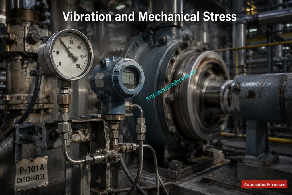
Why Vibration Shortens Instrument Life
Rotating equipment such as pumps, compressors, and blowers can transfer vibration into nearby instruments, tubing, junction boxes, and cables. Over time, this mechanical stress creates fatigue. That fatigue can cause loose fittings, cracked tubing, failed brackets, and unstable readings.
Instruments Most Affected by Vibration
Pressure gauges, pressure transmitters, flow meters, local indicators, junction boxes, and cable terminations often suffer when vibration is high. A gauge near a reciprocating pump may begin to shake, then fail early. A transmitter mounted too close to a vibrating machine may show repeated faults even after replacement.
Field Symptoms of Vibration Related Failure
When the same instrument keeps failing in the same place, the machine or structure should be inspected, not only the device. Vibration, pulsation, and mechanical stress often explain why the same asset fails again and again. The root cause may be poor mounting, weak support, or high process pulsation.
Practical Ways to Reduce Vibration Damage
Use vibration resistant mounting where necessary. Install dampers or snubbers when service requires it. Avoid placing instruments near rotating equipment if feasible. Use adequate clamps, flex supports. Check for tubing fatigue, bracket rigidity during maintenance. A stable mounting arrangement can extend instrument life significantly.
Identify PLC Analog Signal Faults Using Real Plant Scenarios: Troubleshooting Analog Output Signals in PLC Loops – Advanced Scenario-Based Quiz for Process Industries
Calibration Drift
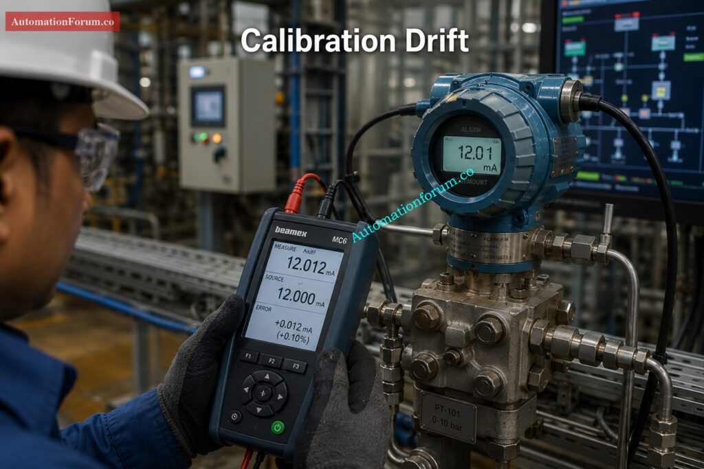
How Drift Develops Slowly Over Time
Why Drift Affects Accuracy and Control Quality
Drift can come from sensor aging, thermal cycling, electronics degradation, mechanical wear, or long term exposure to difficult process conditions. Some instruments drift slowly for months before the issue becomes noticeable in the plant.
How to Identify Drift in the Field
A drifting instrument can look normal while quietly affecting production quality, batching accuracy, safety margins, and control performance. If the reading is wrong but still believable, operators may not notice the problem until the impact becomes significant.
How to Control Calibration Drift
The best way to manage drift is to base calibration intervals on service severity and risk, not just on the calendar. As found and as left data should be tracked carefully. Instruments with a history of drift should be watched more closely. Critical loops may need shorter calibration intervals. Drift trends should also be discussed during reliability reviews so weak assets can be identified early.
Avoid Dangerous Safety Bypass Mistakes During Plant Maintenance: IEC 61511 Safety Bypass And Override in Instrumentation and Control System Maintenance
Electrical Problems
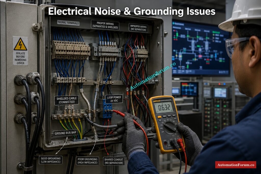
How Noise and Grounding Issues Affect Signals
Many field issues are not mechanical at all. They are electrical. Ground loops, EMI, RFI, poor shielding, loose terminals, poor earthing, power fluctuations, and bad cable routing can create noise that distorts the signal.
Common Electrical Faults in Instrumentation
A transmitter output may fluctuate even when the process is stable. A communication signal may fail intermittently. A DCS input may show spikes or random alarms. These symptoms often point to wiring, grounding, or shielding issues rather than a bad transmitter.
Why 4 to 20 mA Loops Become Unstable
Before replacing a device, the loop should be checked properly. Signal and power cables should be separated where required. Shield termination should follow good practice. Terminal tightness should be verified during preventive maintenance. Loop voltage and load resistance should also be checked. In many cases, the transmitter is innocent and the wiring is guilty.
Best Practices for Grounding and Shielding
Use single point grounding practices where appropriate. Keep signal wiring away from power circuits. Maintain clean terminations. Verify continuity during troubleshooting. A stable electrical foundation protects every device in the loop.
Unlock Predictive Maintenance Using Advanced Heartbeat Technology Diagnostics: Heartbeat Technology in Process Instrumentation – Complete Working, Diagnostics, Verification & Predictive Maintenance Guide
Process Related Problems
Sometimes the instrument is healthy but the process is not
In some services, the process itself becomes the enemy. Plugging, scaling, fouling, corrosion, overpressure, cavitation, steam hammer, and blocked impulse lines can make a healthy instrument appear faulty.
Why Dirty Services Need Special Attention
When the process contains sludge, solids, or scaling material, normal instrument service becomes difficult. A level transmitter may read incorrectly because the impulse line is blocked. A flow meter may become unstable because buildup affects measurement. A pressure device may respond slowly because the service is not clean enough for the chosen arrangement.
Why process access matters
In dirty or slurry service, maintenance access should be planned from the beginning. Flush, purge, or seal arrangements may be needed. Material selection should match the process chemistry. Manifolds and impulse lines should be easy to inspect. A service that looks manageable on paper can become a serious reliability issue if access is poor.
How to reduce process related failures
Choose the correct instrument for the service. Review material compatibility carefully. Watch for buildup, scaling, and corrosion. Improve maintenance intervals where needed. The plant should be designed for the real process, not the ideal one.
Strengthen Smart Plant Reliability with Cyber-Secure Maintenance Practices: Advanced Integrated Field Instrument Reliability & Cyber-Secure Maintenance Checklist for Smart Process Plants
Wrong Instrument Selection
Why the Wrong Selection Creates Repeat Failures
Even the best installation cannot save an instrument that was chosen for the wrong duty. If the wetted material is wrong, the pressure range is wrong, the temperature rating is wrong, or the hazardous area classification is not suitable, failure will come early.
Common Selection Mistakes in Process Plants
Plants sometimes choose the wrong wetted material, the wrong accuracy class, the wrong enclosure, or the wrong pressure and temperature range. A transmitter installed in corrosive service with unsuitable wetted parts may work for a short time and then fail repeatedly. The problem is not poor luck. The problem is selection.
Why Lifecycle Cost Matters More Than Purchase Price
The cheapest instrument is often the most expensive one over the lifecycle. A slightly better selection can reduce replacement work, avoid repeat faults, and improve reliability for years. The purchase price is only one part of the total cost.
How to Choose the Right Material Range and Rating
Review process chemistry carefully. Check material compatibility. Confirm hazardous area requirements. Match range and accuracy to the real process need. Think about maintenance, spares, and long term reliability, not only initial cost.
Avoid Foundation Fieldbus Installation Errors in Critical Process Plants: Foundation Fieldbus Installation and Best Practices – Complete Guide for EPC and Maintenance Engineers
Poor Maintenance Practices
How Weak Maintenance Creates Repeat Breakdowns
Many plants do not have one major instrument problem. They have repeated small maintenance mistakes that slowly damage reliability. Skipped calibration, dirty junction boxes, poor documentation, missing spares, and temporary bypasses left in service all create risk.
Why Preventive Maintenance Must Be Practical
Maintenance should do more than make the instrument work again. It should restore the full reliability of the loop. If a problem returns after every shutdown, the real issue is not being solved. Cleaning a device without fixing the fundamental cause is just postponing the next problem.
How Maintenance Teams Can Improve Reliability
Build a preventive maintenance plan based on criticality. Keep good records. Replace broken seals, glands & terminals. Maintain spare inventory for critical loops. Review recurring faults in root cause analysis meetings. Good maintenance is disciplined, not reactive.
Instantly Calculate Instrument Failure Rates for Better Maintenance Planning: Failure Rate (λ) Calculator for Process Instrumentation and Industrial Maintenance
Human Error
Wiring Scaling and Configuration Errors
Wrong wiring, wrong scaling, wrong configuration, and wrong commissioning actions often look like equipment faults. A bad parameter entry can create a reading that seems impossible. A reversed wire can look like a dead transmitter. A wrong range setup can mislead operators and start a long troubleshooting effort.
Common human error examples
Typical mistakes include wrong input scaling in the DCS, incorrect range setup in the transmitter, reversed wires, bad parameter entry, and missed checks during FAT or SAT. These are preventable errors, but they happen often when time pressure is high.
Why loop checking matters
Loop checking confirms wiring, scaling, polarity, and signal integrity before startup. It is one of the simplest ways to prevent commissioning errors. Every parameter change should be treated carefully because small configuration mistakes can create serious process confusion.
Reduce PLC I/O Failures with Proven Maintenance Strategies: Proactive Maintenance Strategies for PLC I/O Modules: Reduce Downtime & Improve Reliability
Top 10 Instrument Failures Seen Most Frequently in Process Plants
| Instrument | Common Failure | Main Cause | Typical Symptom | Prevention |
| Pressure transmitter | Drift / false reading | Installation, vibration, impulse issues | Unstable pressure value | Correct mounting, regular checks |
| Temperature transmitter | Sensor drift / open circuit | Heat stress, aging, wiring fault | Erratic or frozen PV | Correct sensor selection, PM |
| Control valve | Hunting / stiction | Wrong tuning, wear, air supply issues | Fluctuating output | Proper tuning and actuator maintenance |
| Radar level transmitter | False echo / signal loss | Foam, buildup, installation error | Wrong level indication | Correct nozzle setup and cleaning |
| Flow meter | Bad measurement | Grounding, fouling, improper straight run | Unstable flow reading | Follow installation rules |
| Solenoid valve | Coil failure / sticking | Moisture, dirt, voltage issue | Valve not switching | Dry, clean, proper supply |
| Analyzer | Sample system fault | Plugging, contamination | Wrong analysis result | Sample conditioning PM |
| PLC I/O | Channel failure / noise | Wiring, grounding, power issue | Input/output mismatch | Check wiring and shielding |
| Positioner | Calibration / air leak | Air quality, wear | Slow valve response | Air prep and periodic tuning |
| Limit switch | Mechanical failure | Misalignment, corrosion | No status feedback | Inspection and alignment |
Improve Equipment Reliability Using Accurate MTBF Calculation Methods: Mean Time Between Failures (MTBF) Calculator for Process Instrumentation Maintenance
Real Industrial Failure Case Studies
Case 1 False level due to plugged impulse line
A tank level kept reading high even though the actual tank level was normal. At first, the operator team suspected a transmitter fault, but the real issue was a blocked impulse line caused by sludge buildup. The blockage prevented the pressure from reaching the instrument correctly, so the reading stayed misleading. After the line was cleaned and the flush arrangement was improved, the problem reduced significantly. This kind of case is very common in dirty service, and it shows that false level often starts with plugging, not with electronics. In many plants, the instrument is only the messenger. The real fault is in the process connection or installation method.
Troubleshoot Guided Wave Radar Transmitters Before Production Problems Escalate:Guided Wave Radar Level Transmitters: Complete Troubleshooting & Maintenance Guide
Case 2 Unstable flow reading due to grounding problems
A flow transmitter started giving noisy and unstable readings even though the process itself was steady. The measurements were jumping about . The operators thought the transmitter was going bad . The actual cause was revealed to be inadequate grounding practice after analyzing the loop continuity, cable routing, shield termination and grounding points. The signal was stable again once the shield and grounding were fixed. This is a good example of how electrical issues can look like process problems. Before replacing a transmitter, the loop should always be checked carefully because noise in the wiring can create the same symptoms as a bad instrument.
Case 3 Control valve hunting due to wrong tuning
A process line began to oscillate repeatedly, and the control valve kept opening and closing in an unstable manner. At first, the controller was blamed, but the real issue was a combination of aggressive PID tuning and a valve that was already sticking. The control was overly aggressive and the valve was not moving smoothly enough to give solid control. After the loop was retuned and the valve internals were serviced, the process became much more stable. This case shows that control problems are usually system problems, not controller problems alone. A valve, actuator, positioner, and controller all work together, so one weak point can disturb the entire loop.
Download Powerful Maintenance Checklist to Avoid Unexpected Plant Failures: Maintenance Checklist
Case 4 Water ingress in a junction box
During the rainy season, one area of the plant experienced repeated trips and intermittent signal loss. At first, the fault appeared to be random because it came and went with the weather. Upon opening the junction box, it was found to have dampness, corrosion and unsecured terminals. The cable glands were not sealing correctly and water had been getting into the enclosure over time. The problem was remedied with the replacement of the glands and the improvement of the enclosure protection. This example demonstrates that a little sealing failure can result in a huge dependability problem. A junction box may look fine from the outside, but once moisture reaches the terminals, the whole loop can become unstable.
Case 5 Pressure gauge damage from pulsation
A pressure gauge installed near a reciprocating pump failed much earlier than expected. Before it failed completely, the needle became unstable and difficult to read. Subsequently, the bourdon tube fractured under constant pulsation and mechanical stress. The gauge itself wasn’t the problem. The real issue was the severe pulsation from the pump and the location of the installation. After a snubber was added and the gauge was repositioned, the failure rate dropped. This case is a strong reminder that mechanical stress can shorten instrument life very quickly. In high vibration or pulsation service, the installation method matters as much as the instrument quality.
Perform Marshalling Cabinet Shutdown Maintenance Without Missing Critical Steps: Shutdown Maintenance Procedure for Marshalling Cabinets in Process Plant
How to Reduce Instrument Failures by More Than 50 Percent
Start With Correct Installation
Good installation removes many future problems before they ever begin. If the instrument is mounted properly, connected properly, and supported properly, the chance of failure drops a lot. Proper routing, correct orientation, clean wiring practice, and good accessibility all matter from the beginning. A plant can save a huge amount of troubleshooting time later by doing the installation work correctly during construction or commissioning.
Build a Realistic Maintenance Plan
Track Drift and Failure History
As found records, calibration results, and repeated fault patterns tell a lot about the health of an instrument. If one transmitter keeps drifting faster than the others, that is a warning sign. If the same loop keeps failing after every shutdown, the underlying cause needs to be reviewed. Failure history helps the plant identify weak assets before they create major trouble. This is one of the simplest and most effective ways to improve reliability over time.
Protect Instruments From Environment and Vibration
Heat, moisture, dust, and corrosion can slowly destroy field instruments. This is why enclosure selection, gland sealing, panel protection, and regular inspection are so important. Instruments exposed to sunlight, rain, chemical vapors, or washdown conditions need the right protection from the start. A small investment in environmental protection can prevent many repeated failures later.
Improve Grounding Shielding and Loop Checking
Reduce vibration at the source
If the source of vibration is not controlled, repeat failure is very likely. Instruments mounted near pumps, compressors, and other rotating equipment need special attention. Snubbers, dampers, better support, and improved location can all help reduce mechanical stress. When vibration is ignored, even high quality devices can fail again and again in the same place.
Select the right instrument
The best instrument is not the one with the lowest price. It is the one that matches the process, environment, and duty correctly. Material compatibility, pressure range, temperature rating, accuracy, enclosure type, and hazardous area certification all matter. A well selected instrument usually gives better performance, lower maintenance effort, and longer life. Selection mistakes are expensive because they create repeat problems for years.
Use Root Cause Analysis for Repeat Problems
If the same failure happens twice, it is no longer random. It is a process issue that needs attention. Root cause analysis helps the plant move beyond the symptom and find the real reason for failure. Whether the issue is plugging, vibration, moisture, wiring, or operator error, the lesson is the same. Fixing the device without fixing the cause only delays the next breakdown. Root cause analysis is one of the most valuable habits in instrumentation reliability.
Download : Advanced Instrumentation Failure Prevention Checklist for Process Plants
Prevent Expensive Control Valve Breakdowns Using Proven Inspection Steps: Control Valve Preventive Maintenance Checklist and Inspection Procedure
FAQ on Instrument Failures on Process Industry
Why do pressure transmitters fail in process plants?
Pressure transmitters fail because of vibration, impulse line blockage, penetration, corrosion and improper installation procedures. Good reliability requires correct installation and maintenance.
What causes calibration drift in industrial instruments?
The calibration drift is due to sensor aging, heat cycling, harsh process conditions, and degradation of the electronics. The device slowly loses its accuracy in measurement.
How does vibration damage industrial instrumentation?
Vibration causes mechanical stress on fittings, destroys tubing, breaks brackets, and impairs stability of signals. Instruments near whirling machines are extremely susceptible.
What is the most common instrument failure in industry?
The most typical failures include pressure transmitters, control valves, impulse lines and electrical signal difficulties. Most failures relate to installation and maintenance.
How can grounding problems affect 4 to 20 mA signals?
Poor grounding causes electrical noise to the loop, which results in unstable readings, erratic spikes, and communication mistakes. Proper earthing and shielding are required.
Why do impulse lines get blocked in instrumentation systems?
Impulse lines get obstructed due to sludge, scaling, condensate build-up, dirt and improper routing procedures. Blocked lines might give erroneous pressure and level measurements.
Why do instruments fail more during rainy seasons?
Failures typical to the rainy season include water entry, humidity, condensation and corroded terminals. Failure of poor cable gland sealing increases the likelihood of signal loss.
How can wrong instrument selection reduce plant reliability?
Wrong material selection, wrong pressure range and wrong enclosure ratings lead to recurring failures. An appropriately chosen tool has a longer life and works better.
Why is loop checking important during commissioning?
Loop check is used to verify wiring , scaling , polarity , and signal integrity before startup . It helps to avoid mistakes during commissioning and wrong readings of instruments.
Can poor maintenance create repeat instrument failures?
If not maintained properly, the same problems dirty terminals, skipped calibration, damaged seals keep happening over and over again, resulting in failures. Preventive maintenance increases reliability.
How does a control valve create process instability?
Stiction, air leaks or tuning difficulties in a control valve can produce oscillation, unstable flow and poor process control. Valve condition directly affects loop performance.
How do plants reduce instrument failures quickly?
Plants reduce failures by improving installation quality, grounding, calibration discipline, vibration control, and preventive maintenance practices. Root cause analysis is also critical.
Why do flow meters give unstable readings?
Flow meters give unstable readings due to grounding problems, air bubbles, fouling, wrong straight run and vibration. Proper installation enhances measurement accuracy.
What causes false level indication in tanks?
Generally, false level indication is caused by clogged impulse lines, foam, scaling, moisture or wrong transmitter installation. Regular inspections are a check against errors.
Why does electrical noise affect instrumentation systems?
Electrical noise disrupts low level signals and causes unreliable readings, communication failures and false alarms. The proper cable routing and shielding helps prevent interference.
Why do control valves start hunting?
Control valve hunting can be caused by excessive PID tuning, sticky valve internals, insufficient air supply or large valves. Stable tuning enhances process control.
What causes moisture ingress in junction boxes?
Water infiltration might be due to defective gaskets, insufficient gland sealing, cracked enclosures or incorrect installation. Inside the box, water creates corrosion and signal difficulties.
Why do pressure gauges fail near pumps?
Pressure gauges fail near pumps because pulsation and vibration damage the bourdon tube and internal mechanism. Snubbers and proper mounting reduce failure rates.
What are the signs of calibration drift?
Symptoms include steady yet inaccurate readings, frequent offset during calibration, and progressive drift over time. Drift impacts accuracy and quality of processes.
Why is preventive maintenance important for instrumentation?
Preventative maintenance detects wear, corrosion, loose terminals and drift before failure. It saves downtime and increases the reliability of the plant.
How does poor cable routing affect instrumentation signals?
Improper cable arrangement will expose signal cables to electrical interference and mechanical damage. This can cause readings to become unreliable and problems with communication.
Why do transmitters fail repeatedly in the same location?
Repeated transmitter failure usually points to vibration, heat, moisture, or installation problems in that area. The environment must be checked, not only the device.
What causes unstable DCS process values?
Unstable DCS values are generally the result of noisy signals, grounding difficulties, vibration, poor tuning, or bad field wiring. Always verify signal quality first.
Why is root cause analysis important in instrumentation?
Root cause analysis discovers the true reason of the problem so failures do not occur again. It means more reliability and no unneeded replacement work.
Access Complete Preventive Maintenance Procedures for Instrumentation Systems: Collection of Preventive Maintenance (PM) Procedures for Instrumentation and Control Systems
Conclusion: The Real Secret Behind Instrument Reliability
Most instrument failures are not mysterious. They are the result of repeated field conditions that can be understood and controlled. Poor installation, harsh environments, vibration, calibration drift, electrical noise, process plugging, wrong selection, weak maintenance, and human error all play a major role in plant reliability.
For instrumentation professionals, the lesson is simple. Do not stop at the symptom. Look for the root cause, study the service condition, and fix the real problem. When plants do that consistently, they protect uptime, reduce waste, improve safety, and extend the life of every instrument in the field.
If you would like, I can also turn this into a full blog post with an SEO title, meta description, FAQ schema style section, and a clean WordPress ready format.
Refer the below link to Track Critical Maintenance Metrics That Maximize Plant Reliability Performance