| Valve Type | FL | xT |
|---|---|---|
| Globe – Full Port | 0.90 | 0.72 |
| Globe – Reduced Port | 0.85 | 0.60 |
| Butterfly (60°) | 0.68 | 0.40 |
| Butterfly (90°) | 0.55 | 0.30 |
| Ball – Full Bore | 0.55 | 0.30 |
| Rotary Globe | 0.85 | 0.60 |
| Angle Valve | 0.80 | 0.65 |
| Const | Q Units | P Units | Value |
|---|---|---|---|
| N₁ | gpm | psi | 1.00 |
| N₁ | m³/h | kPa | 0.0865 |
| N₁ | m³/h | bar | 0.865 |
| N₂ | d,D mm | — | 0.00214 |
| N₆ | W lb/h | psia | 27.3 |
| N₆ | W kg/h | kPa | 0.948 |
| N₇ | scfh | psia | 1360 |
| N₈ | kg/h | kPa | 0.948 |
| Fluid | M (lb/lbmol) | γ | Pc (psia) |
|---|---|---|---|
| Air | 28.97 | 1.40 | — |
| Steam (sat) | 18.02 | 1.135 | 3206 |
| Methane CH₄ | 16.04 | 1.31 | 667 |
| Nitrogen N₂ | 28.01 | 1.40 | 493 |
| CO₂ | 44.01 | 1.30 | 1072 |
| Propane C₃H₈ | 44.10 | 1.13 | 616 |
| Water (liquid) | 18.02 | — | 3206 |
| Hydrogen H₂ | 2.02 | 1.41 | 188 |
Control Valve Sizing Calculator and Why Correct Valve Sizing Matters
Control valves are the final control elements that have a direct effect on the safety, stability, and efficiency of a process. Proper size makes sure that flow management is correct, the loop works well, and the equipment lasts a long time. The control valve sizing calculator is an important tool for instrumentation engineers. It helps them figure out the Cv value they need based on things like pressure, temperature, flow rate, and fluid characteristics.
One of the most common mistakes engineers make while working on EPC projects and plant maintenance is not sizing valves correctly. A valve that is too small can’t supply the flow that is needed, which limits productivity and makes the process unstable. An oversized valve works close to the closed position, which makes it hard to control, generates oscillations, wears out the actuator too rapidly, and makes PID tuning unreliable.
If you size anything wrong, it could cause severe mechanical and operational problems, like:
- Cavitation and flashing damage to valve trim
- Excessive vibration and noise
- Premature valve seat erosion
- Reduced rangeability and poor control resolution
- Increased maintenance frequency
- Actuator overloading
A reliable control valve sizing calculator that follows the ANSI ISA valve sizing standard will help you acquire the proper valve and avoid costly failures.
What is Control Valve Cv? Definition, Units, and Flow Capacity Meaning
Cv, or flow coefficient, is the most significant number for sizing valves. It shows how much flow a valve can handle.
Definition:
A Cv is the amount of water that flows through a valve at 60°F and a pressure drop of 1 psi, measured in US gallons per minute.
Engineers can use this term as a standard reference to compare valves from different sizes and brands.
Physical Meaning
Cv is a measure of how easily fluid can pass through a valve. A higher Cv signifies a higher flow rate.
For instance:
- Cv = 1 → small flow capacity
- Cv = 50 → medium flow capacity
- Cv = 500 → large flow capacity
For each size and trim of valve, valve makers list the Cv values.
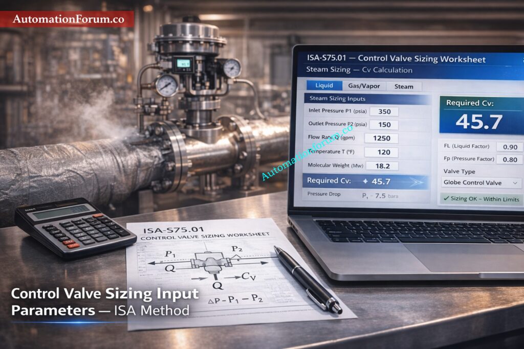
Control Valve Cv Formula Based on ISA S75.01 for Liquid, Gas, and Steam Applications
The simplified ISA S75.01 valve sizing equation for liquid service is:
Cv = Q × √(Gf / ΔP)
Where:
- Cv = flow coefficient
- Q = flow rate (gpm)
- Gf = specific gravity
- ΔP = pressure drop (psi)
This formula shows:
- Cv increases with flow rate
- Cv decreases with higher pressure drop
- Cv increases with higher fluid density correction
The Cv formula for gas and steam control valves has extra correction variables like expansion factor and compressibility.
Control Valve Rangeability and Turndown Ratio Explained: Understanding Rangeability vs Turndown Ratio in Control Valve Sizing
ANSI ISA S75.01 Control Valve Sizing Standard and Its Importance in EPC Projects
The ANSI ISA valve sizing standard ISA S75.01 has formulae and correction factors that are approved around the world.
This standard makes ensuring that sizing is the same and reliable throughout industries, such as:
- Oil and gas
- Power plants
- Chemical plants
- Pharmaceutical industries
- Petrochemical plants
ISA standard covers three major fluid categories:
Liquid valve sizing
Considers:
- Specific gravity
- Vapor pressure
- Cavitation risk
- Valve recovery factor
Gas valve sizing
Considers:
- Compressibility
- Molecular weight
- Expansion factor
- Choked flow
Steam valve sizing
Considers:
- Steam pressure
- Temperature
- Density
- Critical flow conditions
Using ISA formulae makes ensuring that valves are the right size for liquid gas steam applications.
Download Liquid Control Valve Sizing Excel Calculator: Control Valve Sizing Excel tool Without Iteration: Liquid Application
How a Control Valve Sizing Calculator Works and Why Engineers Use It
A control valve sizing calculator makes ISA S75.01 Cv calculation easier by automatically figuring out Cv based on process inputs.
Engineers enter process values like pressure, flow, and temperature instead of doing the math by hand.
Then the calculator gives:
- Required Cv value
- Choked flow indication
- Cavitation warning
- Engineering report
Example calculator reference:
Benefits include:
- Faster engineering design
- Reduced calculation errors
- Easy scenario comparison
- Standardized engineering documentation
Because of this, the control valve sizing calculator is a must-have tool for instrumentation engineers.
Importance of Cv Measurement in Valve Sizing: Why Measuring Control Valve Cv is Essential for Proper Valve Sizing ?
Control Valve Sizing Calculator Input Parameters Explained
To get an accurate Cv estimate, you need to know what each parameter means.
Upstream Pressure (P1) and Its Effect on Valve Flow Capacity
Before the valve, there is pressure.
More flow energy is available when the pressure upstream is higher.
Measured in:
- psi
- bar
- kPa
You have to utilize absolute pressure for gas and steam.
Downstream Pressure (P2) and Pressure Drop Calculation
After the valve, the pressure.
The difference between P1 and P2 tells you how much pressure drops.
A bigger pressure drop means more flow capacity.
Flow Rate Selection and Why Maximum Flow Must Be Used
Required process flow.
Units include:
- gpm
- m³/hr
- kg/hr
- lb/hr
Always size valve based on maximum required flow.
Specific Gravity and Density Effects on Cv Calculation
Ratio of fluid density to water density.
Water = 1
Example values:
- Oil = 0.8
- Acid = 1.2
Higher density increases required Cv.
Vapor Pressure and Cavitation Risk in Control Valves
- The pressure at which a liquid turns into gas.
- Important for figuring out the size of the cavitation control valve.
- Flashing happens when the pressure downstream of the vapor pressure lowers.
Temperature Effects on Gas and Steam Valve Sizing
Changes the density of fluids and the pressure of vapors.
Very important for sizing gas and steam.
Valve Recovery Factor (FL) and Cavitation Prevention
Shows how well the valve can handle cavitation.
A higher FL suggests a lesser probability of cavitation.
Normal values:
- Globe valve = 0.9
- Ball valve = 0.7
- Butterfly valve = 0.6
Piping Factor (Fp) and Installed Cv Correction
Takes into account losses in the pipe near the valve.
Includes:
- Reducers
- Elbows
- Tees
Ignoring Fp causes undersizing.
Critical and Subcritical Cv Sizing Excel Worksheet: Control Valve Sizing Calculation Worksheet for Critical and Sub-Critical Flow: Excel Tool
Step-by-Step Control Valve Cv Calculation Example for Liquid Service
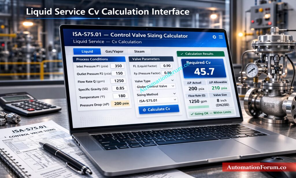
Consider water flow control in a cooling system.
Given:
Flow rate = 200 gpm
Upstream pressure = 100 psi
Downstream pressure = 50 psi
Specific gravity = 1
Step 1: Pressure Drop Calculation Using Upstream and Downstream Pressure
ΔP = 100 − 50
ΔP = 50 psi
Step 2: Applying ISA Cv Formula to Determine Required Valve Cv
Cv = Q × √(Gf / ΔP)
Cv = 200 × √(1 / 50)
Cv = 200 × 0.141
Cv = 28.2
Interpretation of Cv Result and Proper Control Valve Selection
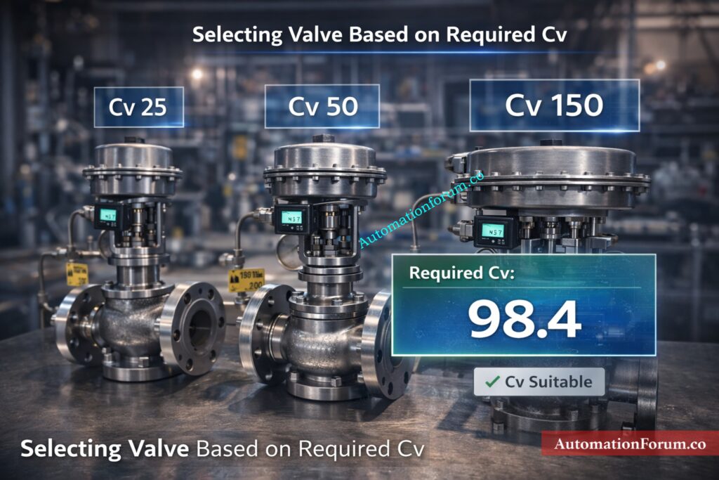
- Required Cv = 28.2
- Select valve with rated Cv slightly higher, such as Cv = 35.
- This ensures sufficient margin.
Valve should operate at:
- 30% to 70% opening
- This ensures stable control and good resolution.
ISA-Based Liquid Cv Calculation Spreadsheet Tool: Control Valve Sizing Excel tool Without Iteration: Liquid Application
Control Valve Sizing for Gas Service Using ISA Expansion Factor
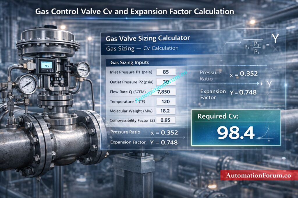
Gas flow is compressible.
Gas expands when the pressure goes down.
The ISA equation has the expansion factor Y in it.
Some important parameters are:
- Molecular weight
- Compressibility factor
- Temperature
- Pressure ratio
Calculating gas Cv is harder.
The control valve sizing calculator does this for you.
Actuator Sizing Calculator and Engineering Method: Valve Actuator Sizing Calculator – Complete Engineering Guide
Steam Control Valve Sizing and Critical Flow Considerations

- Steam acts like gas, but it has its own set of rules.
- The density of steam fluctuates quickly.
- High pressure decreases can make the speed of sound.
- This stops the flow no matter how much pressure drops.
- This is taken into account by ISA sizing formulae.
- The calculator finds important criteria.
Cv Calculator for Liquid, Gas, and Steam Valves: Control Valve Cv Calculation Excel Tool for Liquid, Gas, and Steam Services
Choked Flow in Control Valves: Causes, Detection, and Engineering Solutions
When the speed of the fluid reaches the speed of sound, it chokes.
Raising the pressure drop doesn’t make the flow any faster.
This can lead to:
- Noise
- Vibration
- Trim damage
The calculator automatically finds blocked flow conditions.
If flow is blocked, engineers must choose a particular trim.
Refer the below link for the Control Valve Site Acceptance Test (SAT) Procedure – Step-by-Step Field Guide
Cavitation in Control Valves: Causes, Damage Mechanism, and Prevention
Cavitation occurs when liquid pressure drops below vapor pressure.
Vapor bubbles form and collapse.
This causes:
- Noise
- Trim erosion
- Valve damage
Prevention methods include:
- Multi-stage trim
- Pressure drop reduction
- Proper valve sizing
Control valve sizing calculator helps detect cavitation risk.
Troubleshoot Control Valve Hunting Issues Quiz: Control Valve Hunting Troubleshooting – Advanced MCQ Quiz
Control Valve Noise Prediction and Noise Reduction Methods
High velocity fluid produces noise.
Noise can exceed safe limits.
This causes:
- Equipment damage
- Operator hazard
Proper Cv sizing reduces velocity and noise.
Special trims reduce noise further.
Refer the below link for the Control Valve Noise Prediction Calculator – IEC 60534 Based Engineering Tool
Practical Control Valve Selection Guidelines Used in EPC Engineering
Experienced EPC engineers follow practical rules.
Rule 1: Valve travel range (20%–80%)
- Operate between:
- 20% and 80%
- Avoid extreme positions.
Rule 2: Avoid oversizing
- Oversized valves cause poor control.
- Always use calculated Cv.
Rule 3: Consider rangeability
- Rangeability defines control range.
- Typical values:
- 30:1 to 100:1
Rule 4: Future expansion margin
- Allow margin for increased production.
- Add 10-20% Cv margin.
Rule 5: Verify actuator sizing
- Actuator must overcome process forces.
Rule 6: Choose correct valve characteristic
- Linear, equal percentage, or quick opening.
- Equal percentage most common.
Control Valve Characteristics Selection Guide for EPC: Why Control Valve Characteristics Matter in EPC Instrumentation and Control Engineering
Installed Cv vs Rated Cv and the Effect of Piping Configuration
- Rated Cv is measured in laboratory conditions.
- Installed Cv may differ due to piping.
- Reducers reduce effective Cv.
- Calculator includes piping factor correction.
- Always consider installed conditions.
Free PID Controller Tuning Simulator: Best PID Controller Tuning Simulation Tool for Engineers
Common Control Valve Sizing Mistakes and How to Avoid Them
Engineers often make mistakes including:
- Using gauge instead of absolute pressures for gas and steam gives you the erroneous x and Cv.
- Forgetting about vapor pressure in liquids, which can cause flashing that isn’t expected.
- Copying the nominal pipe size as the valve size without looking at the Cv curves.
- Not taking Fp (installed piping constraints) into account leads to an overestimate of the required Cv.
- Oversizing for maximum flow only and losing control of low flow.
- Not checking the valve choice against vendor data and genuine process changes.
- Ignoring the valve-trim configuration’s minimum controllable flow (deadband).
- Using rough FL values for exotic trims without getting confirmation from the vendor.
- Not taking into account how viscosity changes at different operating temperatures, which changes Cv for viscous liquids.
- Poor communication between the process and procurement teams is causing the assumptions on the data sheets to not match up.
- Using charting water Cv for other liquids without taking into account their specific gravity and viscosity.
- Not checking the piping factor (Fp) after making changes to the site routing, adding valves, strainers, or long welds can affect Fp.
Fix Unresponsive Control Valve in Field: Field Troubleshooting Guide: Control Valve Not Responding in Process Area
Control Valve Sizing Calculator: Benefits of Using an Online Calculator
Major benefits include:
- Improved accuracy: ISA equations applied correctly.
- Faster engineering: Calculation takes seconds.
- Reduced engineering cost: Less manual calculation time.
- Better documentation: Results saved and shared.
- Improved reliability: Correct sizing prevents failure.
How to Select Control Valves for Severe Service: Control Valve Selection and Recommended Practices for Harsh Process Conditions
Control Valve Sizing Calculator: Commissioning and Field Verification
During commissioning:
- Verify actual pressures
- Verify flow rates
- Confirm valve travel
- Adjust PID tuning
- If valve operates near closed position, it may be oversized.
- If fully open, undersized.
- Recalculate using control valve sizing calculator if needed.
Control Valve Datasheet Preparation Guide: How to Prepare Control Valve Datasheets: A Step-by-Step Procedure for EPC Instrumentation Engineers
Control Valve Sizing Calculator: Maintenance Considerations
- Proper sizing improves reliability.
- Maintenance benefits include:
- Less cavitation damage
- Longer trim life
- Reduced actuator wear
- Lower maintenance cost
- Improved plant uptime
- Correct sizing reduces lifecycle cost significantly.
Control Valve Engineering Documentation and Datasheet Requirements
EPC engineers must document:
- Process data
- Cv calculation
- Valve selection
- Vendor datasheet
- ISA calculation method
- This ensures traceability.
- Calculator simplifies documentation.
Vendor Review Checklist for Control Valve Cv, Travel, Cavitation, and Noise
| Parameter | Calculator Result | Vendor Data Needed |
| Required Cv | 28.3 | Cv vs % travel curve |
| Estimated travel at Q | 40% | Actuator torque at 40% |
| Cavitation index | 1.2 | Noise dBA and cavitation test report |
| Choked? | No | Choked flow certification if gas service |
Use a brief table like the one above to make sure you cover all the important tests
Equal Percentage Valve Flow Calculation Tool: Equal Percentage Control Valve Flow Calculator
Real-World EPC Engineering Tips for Accurate Control Valve Sizing
- To avoid mixing up units, make sure that all projects use the same calculator template and that all units and N-constants are the same across the firm.
- When making a data book, you should always run worst-case (min and max) flow scenarios through the calculator. Don’t only look at one point.
- For valves that are very important for safety, use the calculator results along with vendor acceptance tests and make sure the purchase order includes performance guarantees.
- Teach field maintenance crews how to spot the first signs of cavitation (such metallic rattling and louder noise) and keep extra trims on hand for quick replacement.
Control Valve Sizing Calculator: Frequently Asked Questions
How to size a control valve?
To get the right size for a control valve, you need to know the flow rate, upstream and downstream pressures, temperature, and characteristics of the fluid. Then you may use ISA S75.01 formulae to figure out the Cv. The valve you choose should let the most flow through while moving between 20% and 80% of the time. This makes sure that control stays stable and lasts a long time.
How is CV calculated?
Flow rate, pressure drop, and fluid specific gravity are used to figure out Cv. The usual formula for liquids is Cv = flow rate × √(specific gravity ÷ pressure drop). There are also correction factors for gas and steam, like expansion factor and compressibility.
What is the rule of thumb for control valve sizing?
Most of the time, you should choose a valve that opens between 20 and 80 percent of the way. Engineers also leave a Cv margin of 10% to 25% for future growth and dirt buildup. This stops things from getting too big and makes sure that control is accurate.
What is CV in control valve sizing?
Cv is the flow coefficient that shows how much fluid can flow through a valve when the pressure drops by a certain amount. It shows how much flow the valve can handle and is used to compare different sizes and trims of valves. A higher Cv signifies a larger flow capacity.
How to calculate Cv formula?
For liquids, Cv is the flow rate times the square root of the specific gravity divided by the pressure drop. When using the formula, all the units must be the same. When it comes to gas and steam, other things like temperature and pressure ratio are also taken into account.
What is a good Cv value?
A good Cv value is one that lets the valve work in the middle of its travel range while still meeting the highest flow rate. Usually, the Cv of the chosen valve is a little greater than the Cv that was estimated. This gives a safety margin and makes sure that process control stays stable.
Use ISA S75.01 And Control Valve Sizing Calculator To Avoid Failures
For safe and effective plant operation, it is important to size valves correctly. Engineers can use the control valve sizing calculator to correctly do the ISA S75.01 Cv calculation and choose the right valve for applications involving liquid gas and steam. It helps keep things from cavitating, flashing, choking, and becoming unstable, and it also makes process control and equipment life better. Instrumentation engineers can make sure that control valves work reliably, lower maintenance costs, and have the best process control throughout the plant’s life by using a control valve sizing calculator during design, commissioning, and maintenance.
Refer the below link for the Key Control Valve Performance Parameters Explained