- Why a Thorough Control Valve SAT Matters
- SAT Purpose and Scope
- Preparatory Activities – Make the Test Valid and Safe
- Visual & Mechanical Inspection
- Instrument Air Verification (Pneumatic Systems)
- Electrical & Signal Wiring Verification
- Mechanical Stroke & Freedom of Movement
- Actuator & Positioner Functional Testing
- Fail-Safe & Emergency Function Testing
- Seat Leakage, Packing & Gland Tightness Tests
- Position Feedback, Limit Switches & Accessories
- DCS/PLC Integration & Control Loop Interaction
- Common Field Failures, Root Causes & Remedies
- Documentation, Non-Conformance & Handover
- Practical Tips and Field Best Practices
- SAT as a Quality & Safety Enabler
- Control Valve Site Acceptance Test (SAT) Checklist
- Frequently Asked Questions (FAQ) – Control Valve SAT
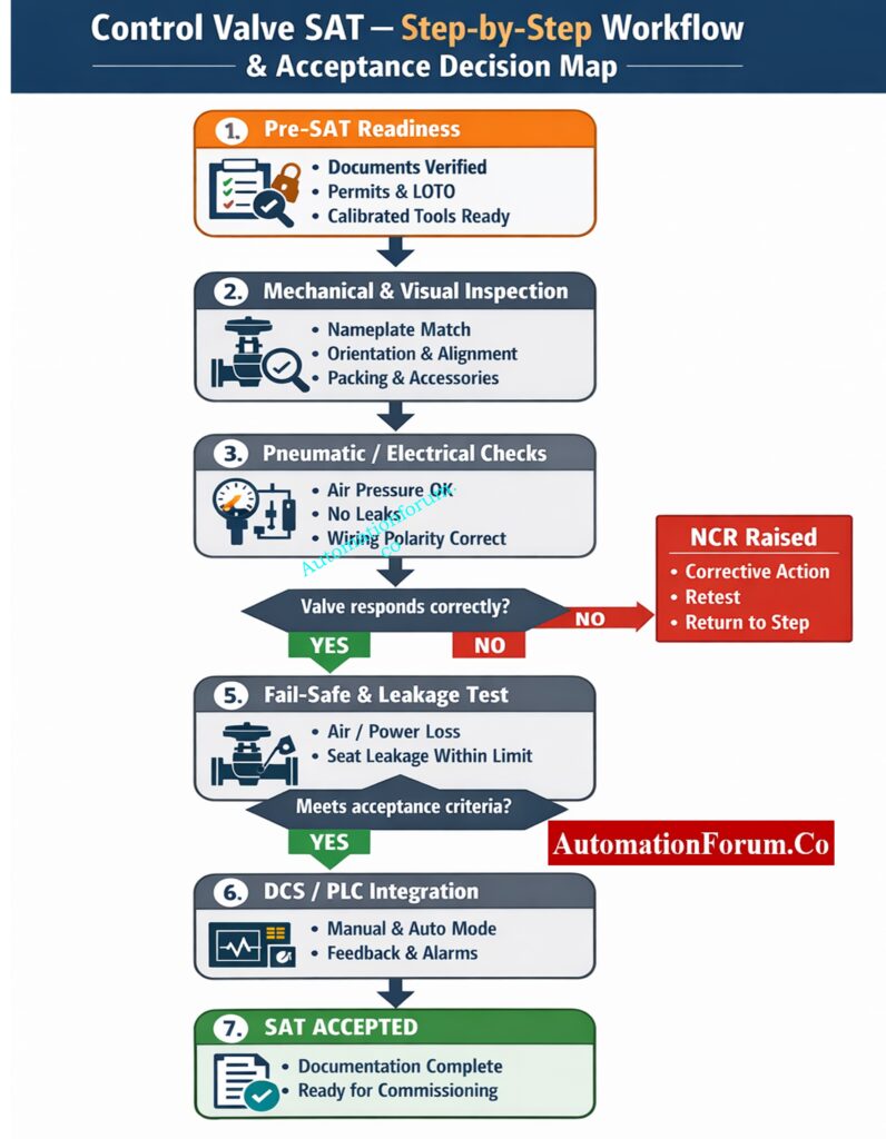
This SAT technique gives instrumentation engineers, commissioning teams, and EPC practitioners a useful, ready-to-use protocol for checking control valves after they are installed and before they are put into use. It expands every activity into explicit, ordered bullet steps so technicians can execute tests reliably, document results, and resolve failures efficiently. This version is written to be used directly on site clear, actionable, and focused on outcomes and safety.
Complete Electromagnetic Flow Meter ITP for EPC Projects (Inspection + Test Steps): Electromagnetic Flow Meter Inspection and Test Plan (ITP): Complete EPC Guide
Why a Thorough Control Valve SAT Matters
A Control Valve Site Acceptance Test (SAT) is the final technical gate before a valve enters service. SAT confirms that what left the factory still performs correctly after transport, installation, and connection to air, power, and control systems. Problems caught at SAT are far cheaper and safer to fix than those found during commissioning or under process conditions. A rigorous SAT improves reliability, reduces startup delays, and protects safety instrument functions.
Marshalling Cabinet FAT Checklist: Step-by-Step Factory Acceptance Test Guide: Factory Acceptance Test (FAT) Procedure & Checklist for Marshalling Cabinets
SAT Purpose and Scope
Purpose: Verify installation, mechanical integrity, actuator/positioner performance, signal and power wiring, fail-safe action, seat/passing leakage as required, and DCS/PLC integration prior to introducing process fluid.
Scope: This includes all control valves (globe, rotary, ball, butterfly), actuators (pneumatic, electric, hydraulic), positioners (pneumatic, electro-pneumatic, smart/HART), limit switches, solenoids, tubing, and any other I/O that is needed to control systems.
Differential Pressure Transmitter FAT – Complete Testing & Acceptance Guide: Factory Acceptance Test(FAT) Procedure for Differential Pressure(DP) Transmitter
Preparatory Activities – Make the Test Valid and Safe
These steps ensure the SAT is meaningful and safe to execute.
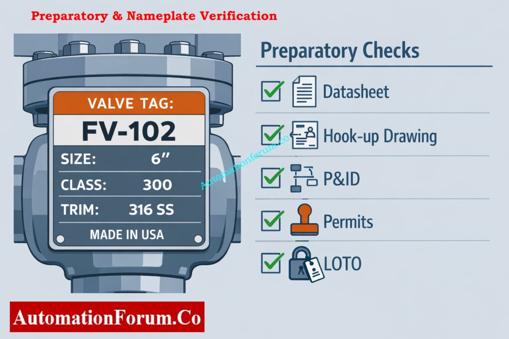
Confirm Documentation & Nameplate Data
- Find the P&ID, loop diagram, hook-up drawings, actuator and positioner instructions, and valve datasheet.
- Verify tag number, valve type, size, pressure class, trim material, flow direction, and rated temperature on the nameplate against the datasheet.
Obtain Permits, LOTO & Notify Control Room
- Get LOTO and work permits for any electrical or mechanical work you need to do.
- Let operations and the control room know about planned signal injections and any fake failures. If necessary, set up a silent window.
Assemble Calibrated Tools & Safety Gear
- Ensure piping and mechanical supports are complete and tight (no temporary supports causing misalignment).
- Make sure that the instrument air header and electrical power are both present and that everyone knows how to use the separated controls.
- Loop calibrator (4–20 mA source/sink), calibrated pressure gauge, timer, multimeter, HART communicator (if needed), socket/torque tools, and soap solution for finding leaks.
Safety preparations
- Check that the team has the right PPE, like hard hats, gloves, and eye protection.
- Ensure rescue and first-aid contacts are known.
Motor-Operated Valve (MOV) FAT: What to Test, Record & Approve: Motor-Operated Valve (MOV) Factory Acceptance Test (FAT) Procedure
Visual & Mechanical Inspection
Perform a methodical visual and mechanical verification before applying signals or pressure.
Nameplate & tag verification:
- Read valve tag and cross-check size, rating, and material with datasheet.
- Check the direction of flow arrow direction with process pipework.
Body, bonnet, and flange checks:
- Look for cracks, dents, paint damage, or signs of damage during shipping.
- Make that the gaskets and flange bolts are there and that they are properly torqued.
Actuator and mounting checks:
- Make sure the actuator type and direction match the drawings.
- Check that the yoke, coupler, and actuator mounting bolts are all tight to the right torque.
- Make sure that the actuator stems and couplings are lined up and not under any sideways force.
Accessory placement:
- Verify positioner, filter-regulator, solenoid valves, volume boosters, and limit switch housings are fitted and accessible.
- Make sure that the tubing is neat, clamped, and has the right supports in place.
Packing and gland inspection:
- Check the gland nuts to make sure they are evenly seated, and make sure the gasket and packing are not leaking or showing signs of deterioration.
Mechanical freedom check (static):
- With actuator depressurized or motor de-energized, confirm manual overrides (if present) move smoothly without binding.
SCADA FAT Activities Explained – Signals, Alarms, Graphics & Reports: Factory Acceptance Test (FAT) Activities for SCADA System: Step-by-Step Checklist
Instrument Air Verification (Pneumatic Systems)
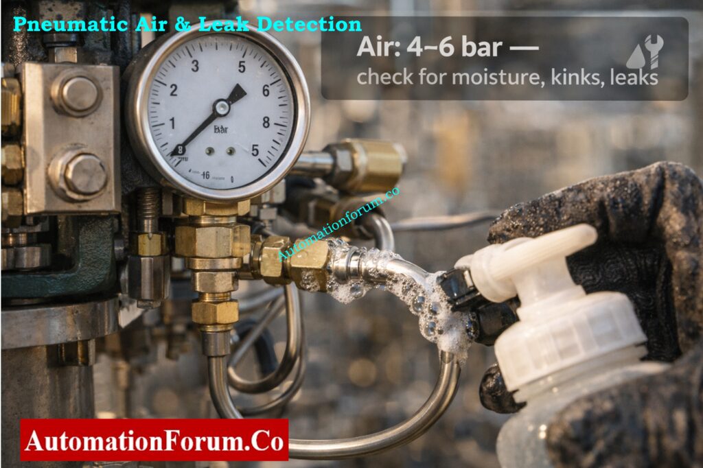
Pneumatic valves depend on correct air pressure and quality. Validate supply and tubing before functional tests.
Air source and FRL checks:
- Measure pressure at the filter-regulator with a calibrated gauge; set to vendor recommended (commonly 4-6 bar / 60-90 psi).
- Check that the FRL bowl is dry and drain it if you need to.
Tubing and connector checks:
- Make sure the tubing is the right size and material, that there are no kinks, and that it has the right slope where condensation drains are supposed to go.
Leak detection on pneumatic side:
- Pressurize actuator and positioner ports; apply soap solution to all fittings and joints; check for bubbles.
Air stability test:
- Cycle the valve slowly while monitoring inlet pressure for significant drops (indicates undersized supply or leaks).
Check accessory operation:
- Manually operate solenoid valves where possible to confirm switching and exhaust routing.
How to Perform Control Valve FAT – Practical Guide for Instrument Engineers: Factory Acceptance Test (FAT) Procedure for Control Valve
Electrical & Signal Wiring Verification
Electrical integrity prevents inverted action, incorrect feedback, and dangerous behavior.
Cable and termination inspection:
- Verify cable type, gland sealing, and terminal torque.
- Check to make sure that the grounding or earthing is still working for electric positioners and actuators.
Loop wiring and polarity:
- Find the IO channel and check the wiring against the loop diagram.
- Check the wiring for 4–20 mA continuity and the right polarity with a multimeter or loop calibrator.
Loop resistance and source checks:
- Make sure the loop resistance is within the range of the transmitter/positioner.
Motor and power checks (electric actuators):
- Check the voltage and phase sequence of the supply.
- Check the settings on the motor protection devices.
Instrumentation device diagnostics:
- If smart/HART device present, connect communicator and read tag, range, and error diagnostics.
PLC Panel FAT Explained – What to Check Before Site Installation: Factory Acceptance Test (FAT) of a PLC Panel: A Step-by-Step Basic Guide
Mechanical Stroke & Freedom of Movement
Before precise tuning, verify unimpeded mechanical motion through full travel.
Initial manual stroke:
- With actuator unpressurized (or motor de-energized), operate manual override if provided and gently move valve through full travel.
- Observe for smooth motion; note any sticking points, tight spots, or sudden resistance.
Full stroke under air/power:
- Apply operating air or energize motor; command full open and full close while observing for uniformity and abnormal sounds.
Record stroke behavior:
- Note speed, noise, friction, or asymmetry. If binding happens, stop the SAT and fix the mechanical problems (packing, misalignment, debris).
Verify end-stop and travel adjustments:
- Make sure the mechanical travel stops are adjusted correctly and not too tightly. Also, make sure the travel stops match the stated travel range.
Control Valve Seat Leakage Test – API Classes, Methods & Limits: Control Valve Leakage Testing, Types, and Calculation Standards
Actuator & Positioner Functional Testing

This is the most important part of SAT: make sure the positioner turns the control signal into exact mechanical travel.
Baseline Zero/Span Setup
- Set 4 mA to closed (or configured action) and 20 mA to open according to tag/spec when the positioner is powered and air is applied.
Multi-Point Verification (4, 8, 12, 16, 20 mA)
- Put in 4 mA, 8 mA, 12 mA, 16 mA, and 20 mA and watch the valve move.
- At each stage, let the position settle down and either write down the reading from the feedback transmitter or see the mechanical indicator.
Linearity, Repeatability, Deadband & Hysteresis
- Cycle the signal up and down through multiple spans; check that the valve returns to the same position for identical signals (repeatability).
- Apply small up/down steps (for example ±0.5 mA) around a point and observe any non-return (hysteresis) or required change before movement (deadband).
- Measure time for full open→full close and vice versa; compare to vendor specification and project requirements.
Positioner Tuning & Smart Diagnostics
- Follow the vendor’s instructions to change the gain, offset, and damping so that the response is acceptable and there is no hunting.
- Retrieve and record diagnostic parameters (supply pressure, valve effort, calibration status) from smart positioners.
Why Control Valves Hunt – Common Tuning, Process & Hardware Mistakes: What are the main causes of control valve hunting?
Fail-Safe & Emergency Function Testing
Fail-safe action must be precise and reliable for safety functions and emergency shutdowns.
- Simulate air loss: With valve in service conditions simulated (or safe test condition), isolate instrument air and observe valve move to fail position.
- Simulate power loss (electric actuators): Turn off the motor supply and make sure that any spring-return or mechanical override works as it should.
- Verify solenoid actions: Turn off the solenoids and check that their exhaust or vent routing allows for safe movement.
- Measure fail time: Keep track of how long it takes to get to the fail position and make sure it is within the permitted range for safety function timing.
- Confirm final state: Check that the valve locks or stays in a safe state, as needed by safety philosophy (for example, stays closed unless manually reset).
Control Valve Positioner Explained – Benefits, Use Cases & Selection Tips: Why You Should Use Control Valve Positioners?
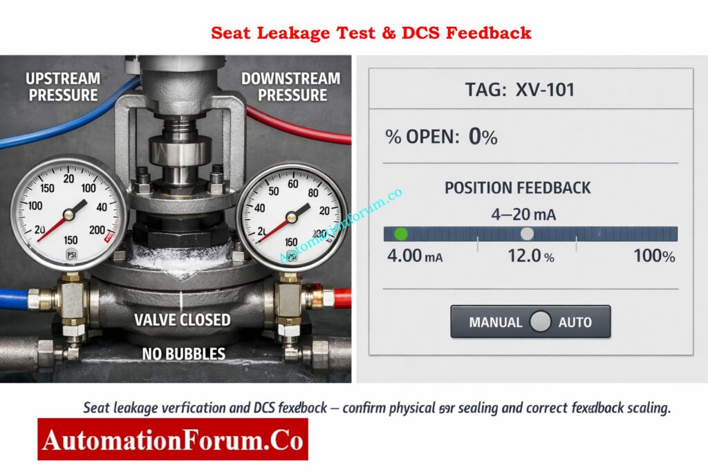
Seat Leakage, Packing & Gland Tightness Tests
Check to see if the valve seat and packing match the standards for isolation and leakage.
Test Isolation & Safety Precautions
Make sure that the upstream and downstream lines are physically separate and that the testing follow all safety and permit rules.
Step-by-Step Seat Leakage Test
- Put the test pressure at the rated or agreed-upon level with the valve fully closed. Then, watch the pressure downstream and use a soap solution at the stem and bonnet to find the paths of leakage.
- Inspect packing area under pressure for visible seepage. Slight seepage may be acceptable depending on packing type document and compare with project limits.
Acceptance Criteria & API Comparison
- Compare observed leakage to contract or API class limits. If leakage is higher than allowed levels, find out what’s causing it (broken trim, wrong seating, foreign material) and fix it.
- After fixing problems, do leakage tests again to make sure the fixes worked.
Control Valve Failure in Process Area – Step-by-Step Diagnostic Guide: Field Troubleshooting Guide: Control Valve Not Responding in Process Area
Position Feedback, Limit Switches & Accessories
Make sure that all status and monitoring signals show the real state of the machine.
- Position transmitter verification: At 0%, 50%, and 100% mechanical travel, check the 4-20 mA position feedback signal and make sure the scaling is right.
- Limit switch checks: Check the limit switches by stroking the valve and turning on the limit switches to make sure the open/closed indicator and wiring to the DCS discrete input are correct.
- Volume booster and relay function: If there is one, check that the volume booster works by sending quick stroke commands to make sure there is no lag or cavitation in the air supply.
- Diagnostic logging: Record any fault codes or alarms presented by smart devices and resolve or escalate per procedures.
DCS/PLC Integration & Control Loop Interaction
Make sure that directives from the control room lead to correct valve behavior and feedback.
Manual Mode Verification From DCS
- From the DCS, place valve in manual mode and send step changes; observe valve respond in the field and confirm feedback mirrors movement.
Auto Mode Dry Run & Loop Observations
- Where safe, place loop in auto mode with simulated or constrained process variables; observe valve response to setpoint changes.
Tagging, Scaling & Alarm Verification
- Confirm DCS displays correct tag, action, percentage open scale, and correct low/high calibration.
Loop behavior and stability
- Look for undesired oscillation, hunting, or irregular response. If present, evaluate valve sizing, positioner tuning, or loop tuning.
Interlock & shutdown checks
- Test cause-and-effect interactions where the valve participates in interlocks or safety trips (simulated where necessary).
What Is PST? Partial Stroke Testing Guide for ESD & Control Valves: What is Partial Stroke Test (PST)? A Complete Guide for Shutdown and Control Valves
Common Field Failures, Root Causes & Remedies
Anticipate typical SAT failures and know efficient corrective actions.
| Symptom observed during SAT | Likely root causes | Recommended corrective actions |
| Valve sticks or hesitates during stroke | Packing overtightened, stem misalignment, debris in seat area, actuator-to-valve misalignment | Inspect valve internals, remove debris, realign stem and actuator, reset packing evenly, retorque fasteners as per vendor specification |
| Incorrect valve action (moves opposite to control signal) | 4-20 mA polarity reversed, positioner action configured incorrectly (direct/reverse) | Verify loop wiring polarity, correct signal connections, reconfigure positioner action, perform functional retest |
| Excessive deadband or hysteresis | Positioner misadjusted, worn valve trim, air leakage in tubing or fittings | Tune positioner parameters, replace worn trim parts, repair pneumatic leaks, repeat linearity and repeatability tests |
| Slow stroke time or low valve speed | Undersized instrument air supply, clogged air filter, damaged or restricted tubing, internal mechanical binding | Increase air supply pressure/flow, clean or replace filters, renew tubing, inspect valve internals for friction or damage |
| Valve does not reach fail-safe position | Incorrect spring orientation, blocked exhaust port, incorrect solenoid valve wiring | Verify actuator spring and cam orientation, clear exhaust paths, correct solenoid wiring, retest fail-safe operation |
Why Control Valves Pass After Maintenance – Causes, Checks & Fixes: How to Troubleshoot a Control Valve Passing Problem after Overhauling: Complete Root Cause Analysis
Documentation, Non-Conformance & Handover
Complete and accurate records turn field tests into acceptance that can be traced.
- Record keeping: Keep track of test dates, people, instruments used (including calibration dates), and specific numeric measurements (pressures, timings, currents).
- Non-conformance reports (NCR): Document any failures with root cause, corrective action, responsible party, and retest plan.
- Device configuration records: Save positioner, transmitter, and smart device configurations and diagnostic logs.
- Vendor/FAT certificates: Attach factory test certificates and calibration reports to the SAT dossier for the valve.
- Acceptance statement: Prepare a clear handover statement describing test scope, results, outstanding issues, and commissioning readiness.
Control Valve Datasheet Explained – Sizing, Materials & Critical Inputs: How to Prepare Control Valve Datasheets: A Step-by-Step Procedure for EPC Instrumentation Engineers
Practical Tips and Field Best Practices
- Little practices reduce rework and improve team efficiency.
- Use calibrated instruments and note their calibration dates directly on test logs.
- Photograph nameplates, installation orientation, and unusual conditions before corrective actions.
- When you can, capture fail-safe and dynamic tests on video so you can look back on them later.
- Never over-tighten packing; make small changes and keep an eye on torque and operational effort.
- Keep extra parts like gaskets, packing, and filter elements on hand for rapid fixes.
- Never put pressure on a line or do leakage tests without the right isolation and permissions.
How to Select Control Valves for Severe Service Applications: Control Valve Selection and Recommended Practices for Harsh Process Conditions
SAT as a Quality & Safety Enabler
A thorough, planned SAT that follows the steps above gives commissioning teams the peace of mind that control valves will work as planned in the plant’s safety and control systems. A thorough SAT takes time, but it lowers the danger of expensive shutdowns, makes things safer, and speeds up the commissioning process. To make sure that commissioning and operations go smoothly, execute SATs with organized paperwork, calibrated equipment, and participation from people in different departments (instrumentation, operations, vendor).
Control Valve Accessories Explained – What Improves Accuracy & Safety: Essential Control Valve Accessories for Reliable Process Control
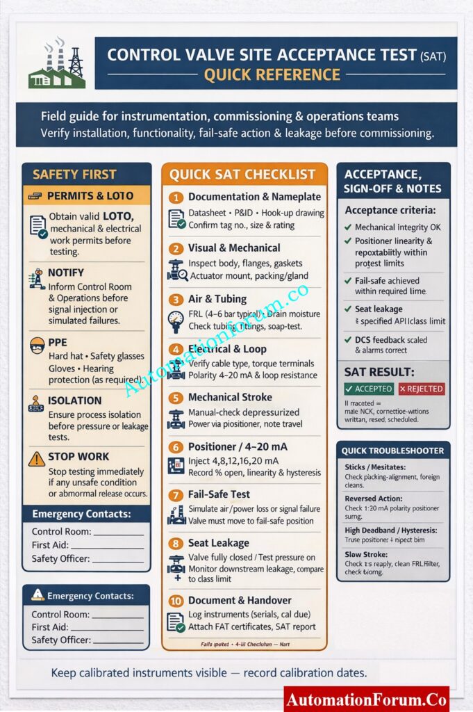
Control Valve Site Acceptance Test (SAT) Checklist
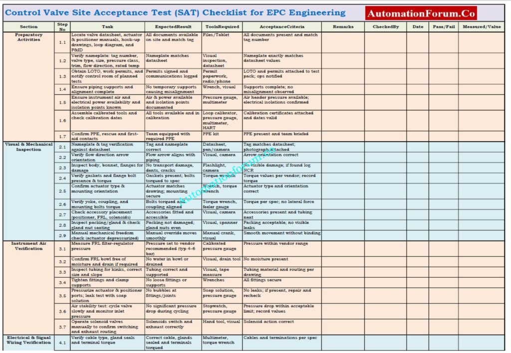
A Control Valve Site Acceptance Test (SAT) checklist is an organized, ready-to-use document that is used after installing the valve and before putting it into service.
This checklist enables the instrumentation and commissioning teams check the mechanical installation, actuator and positioner performance, air and electrical connections, fail-safe action, seat leakage, and DCS/PLC integration in a methodical way.
A complete SAT checklist cuts down on commissioning delays, makes things safer, and makes sure that control valves work exactly as they should.
This Excel checklist is editable and may be used to keep track of test results, acceptance criteria, measurements, and final SAT approval.
Key Control Valve Performance Terms Explained with Practical Examples: Essential Control Valve Performance Parameters
Frequently Asked Questions (FAQ) – Control Valve SAT
What is a Control Valve Site Acceptance Test (SAT)?
A Control Valve SAT is a test done in the field after the valve is installed but before it is put into service.
It checks the mechanical condition, the performance of the actuator and positioner, the wiring, and the fail-safe action.
Before the procedure starts, SAT makes sure the valve is ready to work safely and reliably.
Why is SAT required for control valves?
SAT finds mistakes in installation, damage during transit, and problems with configuration early on.
Fixing errors during SAT keeps the project on schedule and makes sure it starts up safely.
It makes the plant more reliable, safer, and more efficient overall when it is put into service.
What checks are performed during a control valve SAT?
SAT includes checking the air and electrical systems, looking for leaks, stroke testing, and more.
It also checks the calibration of the positioner, the fail-safe action, and the integration of the DCS and PLC.
All outcomes are written down so they can be accepted and handed over.
How do you test actuator and positioner during SAT?
A 4-20 mA signal is sent to several places to make sure the valve moves.
We check the stroke’s accuracy, repeatability, deadband, and response time.
If a digital positioner is installed, smart diagnostics are checked.
How is fail-safe action verified in a control valve SAT?
Under safe settings, instrument air or electrical power is taken away on purpose.
The valve has to move to the defined fail position in the time given.
We keep track of the fail position and stroke time and compare them to safety standards.
What is seat leakage testing in control valve SAT?
Seat leakage testing measures how well the valve closes all the way.
Pressure is put on the upstream side, and leakage is watched on the downstream or outside side.
The results are checked against the limits for project or API leakage classes.
Who is responsible for performing control valve SAT?
Instrumentation and commissioning engineers usually do SAT.
Representatives from vendors and operations teams may also take part.
All stakeholders sign off the SAT for commissioning readiness.
What is the full form of FAT and SAT?
FAT stands for Factory Acceptance Test.
SAT stands for Site Acceptance Test.
FAT is done at the manufacturer’s facility, while SAT is done at site.
What is SAT validation?
SAT validation is the documented confirmation that installed equipment meets design requirements.
It proves that systems perform as intended under real site conditions.
SAT validation is critical for quality assurance and regulatory compliance.
PLC SAT Procedure Explained – From Power-On to Final Acceptance: Site Acceptance Test (SAT) Procedure for PLC Systems