- Introduction to Electromagnetic Flow Meter Inspection and Test Plan
- Why an Electromagnetic Flow Meter ITP Is Critical in EPC Projects
- Scope of the Electromagnetic Flow Meter ITP
- Applicable International Standards for Electromagnetic Flow Meters
- Typical EPC Deliverables for EMFM Quality Control
- Detailed Electromagnetic Flow Meter Inspection and Test Plan (ITP Table)
- Incoming Material Inspection for Electromagnetic Flow Meters
- Vendor Factory Inspection (FAT) for Electromagnetic Flow Meters
- Site Installation Inspection for Electromagnetic Flow Meters
- Pre-Commissioning and Commissioning Tests for EMFMs
- Acceptance Criteria – Expanded Bullet Points
- Final Documentation Requirements for EMFM ITP
- Downloadable Excel Sheet: Electromagnetic Flow Meter Inspection and Test Plan (ITP)
- FAQ on Electromagnetic Flow Meter Inspection and Test Plan (ITP)
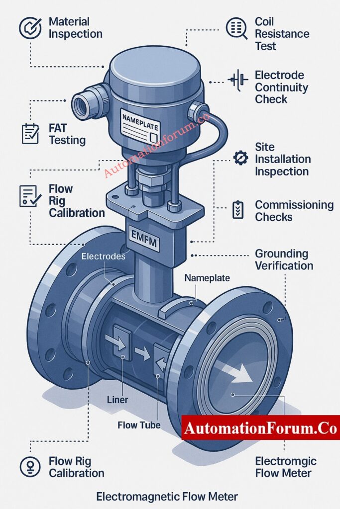
Introduction to Electromagnetic Flow Meter Inspection and Test Plan
What Is an Electromagnetic Flow Meter (EMFM)?
Electromagnetic flow meters (EMFMs) are widely used for measuring flow in many industries, including oil and gas, petrochemicals, water treatment, desalination, wastewater management, food and beverage production, and power generation. Given the importance of these meters in measuring key processes, the Electromagnetic Flow Meter Inspection and Test Plan is a crucial deliverable for any EPC project. It’s essential for guaranteeing quality, dependability, and the meter’s continued performance throughout time.
This guide offers a complete EMFM inspection and test plan. It covers everything from material inspections and Factory Acceptance Testing (FAT) to site installation checks, commissioning processes, and acceptance criteria. You’ll also find documentation requirements and a detailed EPC-style Inspection and Test Plan (ITP) table.
How EMFMs Work – Principle of Faraday’s Law
Don’t Guess — Calculate: Electro Magnetic Flow Meter Installation Calculator: Minimum Length for Reducing Joint
Why an Electromagnetic Flow Meter ITP Is Critical in EPC Projects
Key Risks of Improper EMFM Installation
In engineering, procurement, and construction (EPC) projects, EMFMs are considered crucial instruments because:
- Problems with these components could negatively affect how much a plant produces, its safety, or the quality of the final output.
- Shutdowns are necessary for replacements.
- The quality of installation is a major factor in how well anything performs.
- Adhering to OEM specs and industry standards is non-negotiable.
Benefits of a Well-Defined EMFM ITP
A well-defined Electromagnetic Flow Meter ITP guarantees:
- Tracking the origins of materials.
- Assessing the accuracy of OEM performance assertions.
- Adhering to established standards, including IEC, ISO, API, AWWA, and NEMA.
- Preventing problems with linings, electrodes, coil insulation, or grounding is essential.
- Finalizing QA/QC documentation and ensuring traceability for project closeout.
Scope of the Electromagnetic Flow Meter ITP
This ITP covers all EMFM sensors and transmitters provided for EPC projects throughout:
- Oil and gas facilities, both upstream and downstream.
- Chemical and petrochemical factories are essential to modern industrial processes.
- Power generating and utility systems are essential for modern society.
- Water and wastewater systems.
- The food and beverage sectors.
Stop Overthinking It: Streamlining Your Flowmeter Selection Process: Tips and Insights
Applicable International Standards for Electromagnetic Flow Meters
- IEC 60041, IEC 61010, IEC 61326 (EMC & electrical safety)
- ISO 4064, ISO 6817 (electromagnetic flow measurement)
- AWWA C715 (water utility flow meters)
- API 5.1 / API Q1 (quality systems)
- NEMA 4/4X/6/6P (enclosure ratings)
Typical EPC Deliverables for EMFM Quality Control
- Approved datasheets & GA drawings
- Quality Control Plan (QCP) / ITP
- OEM calibration certificates
- FAT reports
- Material certificates
- Installation method statements
- Commissioning procedures
- As-built documentation
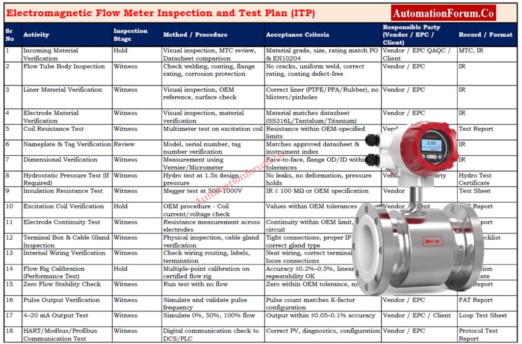
Detailed Electromagnetic Flow Meter Inspection and Test Plan (ITP Table)
EMFM ITP Table – Activities, Stages, Methods, Criteria & Responsibilities
| Activity | Inspection Stage | Method / Procedure | Acceptance Criteria | Responsible Party | Record / Format |
| Material incoming inspection | Hold | Visual, MTC review | Material as per datasheet & EN 10204 | Vendor / EPC QAQC / Client | MTC, IR |
| Liner & electrode verification | Witness | Visual, OEM reference | Correct material, defect-free | Vendor / EPC | IR |
| Coil resistance test | Witness | Multimeter measurement | Within OEM limits | Vendor / EPC | Test report |
| Nameplate verification | Review | Visual | Tag, serial, rating correct | EPC / Client | IR |
| Dimensional check | Witness | Measurement as per GA | Within tolerance | Vendor / EPC | IR |
| Hydro test (if applicable) | Witness | Pressurization | No leakage, holds pressure | Vendor / 3rd Party | Hydro test report |
| Insulation resistance test | Witness | Megger @ 500–1000 V | ≥ 100 MΩ or OEM requirement | Vendor | IR/test sheet |
| Coil excitation check | Hold | OEM procedure | Values within tolerance | Vendor / Client | FAT report |
| Electrode continuity | Witness | Resistance check | Continuity within OEM limit | Vendor | FAT report |
| Terminal box & wiring check | Witness | Physical inspection | Tight, clean, correct | Vendor / EPC | FAT checklist |
| Flow rig performance test | Hold | Calibration on rig | OEM accuracy (±0.2%–0.5%) | Vendor / Client | Calibration certificate |
| Site installation inspection | Witness | Checklist | Orientation, earthing, cable routing OK | EPC / Client | SIT report |
| Pre-commissioning checks | Witness | Power-up, loop checks | Stable signals, no errors | EPC / Client | Pre-commissioning sheet |
| Commissioning & loop test | Hold | 4–20 mA, pulse, protocol tests | ±0.05–0.1% output accuracy | EPC / Client | Commissioning report |
| Final documentation | Review | Compilation check | As per project MDR | EPC / Client | Dossier / MDR |
Make the Right Choice: Magnetic Flowmeter vs. Turbine Flowmeter – Complete 2025 Comparison Guide
Incoming Material Inspection for Electromagnetic Flow Meters
Sensor Body Inspection Requirements
- Confirm that the flow tube’s composition aligns precisely with the material grade described in the datasheet—be it stainless steel, carbon steel, or coated steel. This is crucial for guaranteeing both corrosion resistance and the tube’s fitness for the specific process fluid it will handle.
- Verify flange ratings—ANSI, EN, or JIS—along with the pressure class, bolt-hole pattern, and face type. This ensures everything will fit with the existing piping on-site.
- Examine weld seams closely. Look for consistent appearance, and check for any signs of porosity, cracks, or undercuts. This is essential to confirm the weld’s mechanical soundness.
- Assess the surface coating or paint for thickness, adherence, and uniformity of application. This is crucial for ensuring the material’s durability when exposed to external conditions or corrosive elements.
Liner Material Inspection Checklist
- Verify that the lining material—PTFE, PFA, hard rubber, or polyurethane—matches the specifications provided in the purchase order and datasheet. Any deviation from the approved liner could lead to premature failure.
- Examine the liner’s interior for a smooth finish. It should be devoid of blisters, pinholes, wrinkles, or any deformation that could compromise the precision of the measurements.
- Inspect the liner’s adhesion to the tube, when relevant, looking for any signs of separation or gaps.
Electrode Material Verification
- The electrode material, whether it’s SS316L, Hastelloy, Titanium, or Tantalum, must be compatible with the chemicals used in the process.
- Examine electrode surfaces to ensure they’re clean, well positioned, and free from any scratches or pitting.
- Ensure the electrodes are securely in place; any looseness could lead to erratic measurements.
Coil Resistance Measurement
- Using a calibrated multimeter, measure the resistance of the excitation coil. Then, compare your findings to the specifications provided by the original equipment manufacturer.
- Confirm that the resistance measurements align with the defined ohmic tolerance. This ensures the coils are functioning properly, free from shorted turns or any signs of partial burnout.
- Verify that the resistance levels of both coils are equal in dual-coil designs.
Nameplate & Tag Verification
- Confirm that the model number, serial number, and tag number precisely correspond to what’s documented in the project files and the instrument index.
- Verify operating specifications: maximum flow capacity, pressure tolerances, temperature thresholds, and electrical requirements to ensure adherence.
- The flow direction arrow must be prominently displayed and firmly affixed.
Calibration Certificate Review Checklist
- Calibration must be conducted in a laboratory accredited to ISO/IEC 17025 standards, with traceability to national or worldwide benchmarks.
- Examine test points, error curves, and uncertainty statements to confirm they meet the project’s accuracy standards.
- The certificate must include the instrument’s serial number, the date of the calibration, the ambient conditions throughout the process, and the technician’s signature.
Before Using Any EMFM, Know This: Electromagnetic Flowmeter Working Principle, Types Applications
Vendor Factory Inspection (FAT) for Electromagnetic Flow Meters
Dimensional Verification Activities
- Verify all meter body measurements. This includes checking the face-to-face length, flange thickness, bolt-hole diameter, and internal diameter. The goal is to ensure everything matches the General Arrangement (GA) drawing.
- Check that the gasket surfaces are smooth, flat, and unmarred by any scratches or pitting. This is essential for a leak-free seal.
Hydrostatic Pressure Test Requirements
- Verify the test pressure, which is usually 1.5 times the design pressure. Hold this pressure for the required time, ensuring there are no visible leaks.
- To assess integrity, document the pressure, temperature, and any observed pressure drop.
- Employ safety measures and ensure gauges are properly calibrated.
Insulation Resistance (IR) Test
- Conduct a Megger test, applying 500–1000 V between the coil windings and the meter body. This will help assess the condition of the insulation.
- Unless the original equipment manufacturer (OEM) indicates otherwise, the minimum allowable insulation resistance should be at least 100 MΩ.
- Document readings to ensure traceability and for future use.
Excitation Coil Verification
- Under operational settings, measure the coil’s current and voltage to verify that its performance aligns with the original equipment manufacturer’s requirements.
- Verify that the magnetizing current remains steady and falls within the specified design limits, which confirms the coils are functioning as intended.
Liner Inspection During FAT
- Examine the lining’s whole inside surface. Ensure the thickness is consistent and that there are no surface flaws.
- Inspect the liner’s bond to the metal body; look for any evidence of separation.
- Verify that the liner material is suitable for the chemicals used in the project.
Electrode Continuity Testing
- Check the resistance across the electrode terminals to ensure there’s no excessive resistance or breaks in the circuit.
- Ensure the electrodes are securely fastened and properly positioned to prevent any signal disruptions.
Terminal Box & Internal Wiring Inspection
- Examine the interior wiring. Ensure it’s neatly arranged, correctly labeled, and that all terminal connections are secure.
- Ensure cable glands are the right size, made from the correct material, and have the appropriate IP rating to keep moisture out.
- Make sure the earthing termination is there, properly sized, and free of any corrosion.
FAT Loop Checks (4-20 mA, Pulse, Digital Protocol)
- Simulate a 4–20 mA output and verify the signal’s linearity and accuracy at 0%, 50%, and 100% flow rates.
- Check the pulse output to ensure it’s working correctly, and then verify that the pulse rate aligns with the K-factor setting.
- Check digital communication (HART/Modbus/Profibus) for for accurate process variable readings, device health checks, and seamless data exchange.
Flow Rig Performance Test During FAT
- During Factory Acceptance Testing (FAT), the meter should be calibrated using a certified flow rig. This calibration process involves testing the meter at several flow rates, usually at 20%, 50%, 80%, and 100% of its maximum capacity.
- Confirm that the measurements align with the original equipment manufacturer’s specifications, ensuring accuracy, linearity, repeatability, and a lack of hysteresis.
- Verify that the system maintains zero-flow stability and that there’s no drift in the measurements.
Refer the below link to Avoid Calibration Mistakes: Electromagnetic flowmeter Calibration procedure
Site Installation Inspection for Electromagnetic Flow Meters
Installation Orientation & Straight-Run Requirements
- Install the meter where the pipe stays full of fluid while it’s running. This prevents any inaccuracies in the measurements.
- Inspect the upstream straight-run lengths, ensuring they span 5D to 10D without any interruptions. This means no valves, tees, or reducers should be present.
- Confirm the downstream straight-run lengths of 3D–5D to maintain a consistent flow profile.
Earthing & Bonding Requirements
- Verify that a dedicated grounding conductor has been installed, running from the flow meter to either the earth pit or the grounding grid.
- Ensure bonding jumpers are in place across flanges. This is essential for maintaining electrical continuity, which in turn is critical for accurate signal detection.
- Verify that the grounding resistance aligns with the original equipment manufacturer’s specifications.
Grounding Rings and Electrodes Verification
- Grounding rings are necessary when installing in non-conductive pipes, such as PVC, HDPE, or FRP.
- Confirm that the grounding rings are suitable for the process fluid.
- Verify that the grounding electrode is installed and connected correctly, following the original equipment manufacturer’s guidelines.
Sensor-to-Transmitter Cable Requirements
- To prevent signal loss or electromagnetic interference, stick with the cable type specified by the original equipment manufacturer.
- Ensure the cable’s maximum length, often between 50 and 100 meters, isn’t surpassed.
- To avoid ground loops, make sure the cable shielding is grounded solely at the transmitter end.
Cable Segregation & Shielding Checks
- Twisted pair shielded cable is indeed employed for signal wiring, a choice made to reduce interference.
- To prevent electromagnetic interference, signal cables should be routed away from high-voltage and variable frequency drive (VFD) cables.
- Verify cable tray segregation according to project specifications.
Slurry / Wastewater Installation Considerations
- When setting up systems for slurry and wastewater, several important factors must be considered.
- Keep the electrodes fully immersed; any contact with air can lead to erratic measurements.
- For slurry or applications involving heavy solids, installations are best suited for vertical pipes that flow upwards.
Environmental Protection and IP Rating Verification
- Verify sensor and transmitter enclosures meet required IP rating (IP65/67/68 based on location).
- Inspect cable glands, gaskets, and covers for proper sealing against dust or moisture ingress.
- Confirm sunshade or weather shielding is provided when required.
Think You’re Interview-Ready? Advanced Electromagnetic Flowmeter Interview Quiz for Instrumentation Professionals
Pre-Commissioning and Commissioning Tests for EMFMs
Power-Up Checks
- Check that the sensor and transmitter enclosures are compliant with the necessary IP ratings – IP65, IP67, or IP68, depending on where they’re situated.
- Check cable glands, gaskets, and covers to ensure they’re sealing correctly, keeping out dust and moisture.
- Confirm that sunshade or weather screening is available when needed.
- Pre-commissioning and commissioning tests for EMFMs.
Configuration Parameter Verification
- Program flow units, engineering units, and decimal points should be specified according to the datasheet.
- Check the K-factor, calibration constants, and identify the tube size.
- Implement sophisticated features such as low-flow cutoff and filtration, tailored to the specific needs of each process.
Empty Pipe Detection Testing
- Simulate an empty-pipe scenario and confirm that the meter triggers the correct alarm or fault notification.
- Output must proceed to fail-safe state as programmed.
- Examine the DCS alarm annunciation to ensure it’s correctly mapped.
Zero Calibration Procedure
- Zero the system with the pipe full, ensuring a certified no-flow state.
- Maintain zero drift within the specified tolerance.
- Document the zeroing results for further use.
Functional Tests (Analog, Pulse, Digital)
a) Analog Output (4–20 mA)
- Analog output, specifically in the 4–20 mA range, is a common method for transmitting signals.
- Simulate flow values at 0%, 50%, and 100%, and then check the signal for both correctness and stability.
b) Pulse Output
- Verify that the pulse frequency, pulse width, and polarity align with the specifications given in the system interface.
c) Digital Protocol (HART/Modbus/Profibus)
- Read process variable (PV), setpoint (SV), diagnostics, and device parameters from the Distributed Control System (DCS).
- Confirm the correct identification of devices and the accuracy of their communication pathways.
Interlock & Control Loop Verification
- Simulate interlocks for both low-flow and high-flow scenarios, then confirm that the desired trip or control response occurs.
- Make sure alarms are sent to the DCS system properly, and that their priority are accurately reflected.
- Confirm the accuracy of time stamps and, when relevant, the chronology of events.
Comparison with Reference Flow Measurement
- When project specifications call for it, compare EMFM readings with those from a portable reference meter or an ultrasonic clamp-on flow meter.
- Confirm that the observed difference falls within the established acceptable range, which is usually ±1–2%.
Stop the Failures Now: Electromagnetic Flowmeter Troubleshooting: Identifying and Resolving Issues
Acceptance Criteria – Expanded Bullet Points
OEM Accuracy & Tolerance Requirements
- Maintain accuracy within OEM specifications (usually ±0.2% to ±0.5% of reading).
- Ensure repeatability is within ±0.1% of full scale.
Signal Stability Criteria
- Under stable flow conditions, the analog output should be between ±0.02 mA.
- Digital communication must give consistent, noise-free PV values.
Coil Insulation Acceptance
- Insulation resistance must be at least 100 MΩ, with greater values desirable in humid situations.
- Record and verify the pattern of readings across multiple terminals.
4-20 mA Accuracy Rules
- The output must match test input values within ±0.05% of the measured range.
Display & DCS Verification Requirements
- The transmitter display must accurately display flow, totalizer, and status messages.
- DCS must read the appropriate PV, alarm status, device metadata, and diagnostics.
Don’t Install Before You Read This: Electromagnetic Flow Meter Installation – Step-by-Step Guide and Checklist for Accurate Measurements
Final Documentation Requirements for EMFM ITP
EPC Documentation Dossier Includes:
- Inspection Reports (IR)
- FAT & SAT reports
- OEM Calibration Certificates
- Material Test Certificates (MTC)
- As-built drawings
- Approved datasheets
- ITP sign-off sheets
- Configuration back-up files
- O&M manuals
- Manufacturer data report (MDR)
Importance of a Complete EMFM ITP in EPC Projects
This thorough Electromagnetic Flow Meter Inspection and Test Plan (ITP) offers EPC instrumentation engineers, QA/QC inspectors, and project managers a complete, realistic, and implementation-ready reference.
This article provides full EPC-style coverage, from inbound material checks to FAT, installation inspections, commissioning verification, and final documentation, allowing for consistent flow measurement performance across all industrial situations.
Only Experts Can Score 25/25: Advanced Electromagnetic Flowmeter Troubleshooting Quiz – 25 Expert Questions. Refer the below link
Downloadable Excel Sheet: Electromagnetic Flow Meter Inspection and Test Plan (ITP)
Refer below link to download the Electromagnetic Flow Meter Inspection and Test Plan (ITP)
FAQ on Electromagnetic Flow Meter Inspection and Test Plan (ITP)
What is an ITP inspection test plan?
An Inspection Test Plan (ITP) is essentially a roadmap. It details the specific checks to be performed, the timing of those checks, and the individuals responsible for carrying them out, all within the context of manufacturing or installation processes. This process ensures that all standards are met.
How to test an electromagnetic flow meter?
To put an electromagnetic flow meter through its paces, you’ll need to:
- Inspect the casing, the inner lining, and the electrodes.
- Coil and insulation resistance should be measured.
- Perform loop checks (4–20 mA, pulse, digital).
- Calibrate the flow rig.
- Perform on-site installation checks.
- Perform commissioning tests, including zero calibration and functional assessments.
What is the ITP inspection point?
An ITP inspection point represents a mandatory inspection stage.
Examples encompass Hold, Witness, Review, and Surveillance points.
How to prepare an inspection test plan?
To get an ITP ready:
- List all activities
- Decide what needs to be inspected
- Set acceptance criteria
- Assign responsibilities
- Choose inspection methods
- List required records (reports, certificates)
- Put all items into a table
What are the 7 steps of the inspection process?
The 7 simple steps are:
- Plan the inspection
- Define criteria
- Check visually
- Do detailed tests
- Record results
- Accept or reject
- Submit report
What is an ITP process?
The ITP process is the step-by-step procedure for following the ITP during a project. This involves conducting inspections, observing tests, documenting outcomes, and confirming compliance with quality standards.
 guide for EPC instrumentation engineers. Includes material inspection, FAT, site installation, commissioning tests, acceptance criteria, and downloadable ITP checklist.)