- Why Partial Stroke Testing is Important
- What is a Partial Stroke Test?
- Full Stroke Test (FST) vs Partial Stroke Test (PST) – Key Differences
- How Partial Stroke Testing Works Step-by-Step
- Typical Partial Stroke Range
- Types of Partial Stroke Testing
- Benefits of Partial Stroke Testing
- Diagnostic Parameters in a Partial Stroke Test
- Standards and Guidelines for PST
- Interpreting PST Results
- Limitations and Drawbacks of PST
- Recommended PST Frequency
- Example: PST in a Refinery Shutdown Valve
- Future Trends in Partial Stroke Testing
- Partial Stroke Test (PST) Checklist – Excel Template
- Test Your Expertise with Advanced Control Valve Troubleshooting Quiz
- FAQs on Partial Stroke Test (PST)
Safety and reliability are the most important things in modern manufacturing processes. Shutdown and control valves are very important for automated processes because they keep people, equipment, and the environment safe from dangerous conditions. These valves need to work perfectly when needed, but they typically sit unused for long periods of time.
Engineers utilize a method called the Partial Stroke Test (PST) to make sure that their machines work without stopping production. This simple but effective strategy makes sure that important valves can move when they need to, giving you confidence of mind that the system will work properly if it needs to shut down.
Why Partial Stroke Testing is Important
Common Problems in Idle Valves
In process sectors including oil and gas, refineries, petrochemicals, and power plants, valves often have to work in very severe situations, like high pressure, temperature, and corrosive environments. Many of these valves are emergency or block valves that stay in one position (completely open or closed) for months or even years.
These kinds of valves may get:
- Stem friction or sticking
- Internal corrosion
- Air supply leakage in pneumatic actuators
- Mechanical binding or seal hardening
These problems can stop the valve from moving when a shutdown command is sent, which can lead to hazardous circumstances or expensive downtime.
Traditional Full Stroke Test vs Modern PST Approach
Operators used to depend on Full Stroke Tests (FST) to fully open and close the valve during planned plant shutdowns. But this meant pausing production, which took a lot of time as well as resources.
The Partial Stroke Test is a better option because it lets you check valve movement without stopping work.
Control Valve Passing Issue? Troubleshoot Now: How to Troubleshoot a Control Valve Passing Problem after Overhauling: Complete Root Cause Analysis
What is a Partial Stroke Test?
Definition and Basic Principle
A Partial Stroke Test (PST) is a way to move a valve’s actuator and stem only 10% to 20% of its total stroke to see if the valve responds to control signals and travels freely.
A PST checks the basic health of the mechanics and actuators while keeping the process going normally. This is different from a Full Stroke Test, which needs a full open/close action.
Key Parameters Monitored During PST
During a PST, parameters such as:
- Valve position
- Response time
- Actuator pressure
- Load factor
are monitored and recorded. This information helps maintenance personnel find possible mechanical or pneumatic problems early on, which keeps the machines from shutting down unexpectedly.
Prepare Perfect Control Valve Datasheets: How to Prepare Control Valve Datasheets: A Step-by-Step Procedure for EPC Instrumentation Engineers
Full Stroke Test (FST) vs Partial Stroke Test (PST) – Key Differences
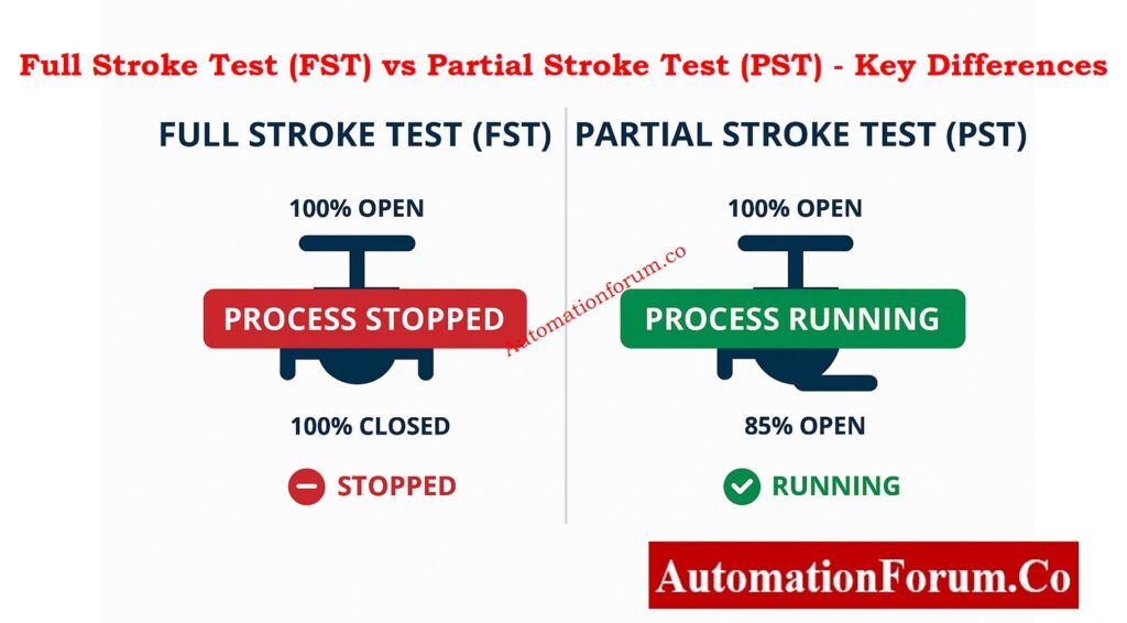
| Aspect | Full Stroke Test (FST) | Partial Stroke Test (PST) |
| Extent of Movement | 100% valve travel (fully open/close) | Typically 10–20% movement |
| Process Interruption | Requires shutdown or bypass | No process interruption |
| Failure Detection | Detects all possible faults | Detects about 70% of common faults |
| Testing Frequency | Done during major maintenance turnarounds | Can be done monthly or quarterly |
| Cost and Effort | High due to downtime | Low – performed online |
| Purpose | Full integrity verification | Routine health check |
How Partial Stroke Testing Works Step-by-Step
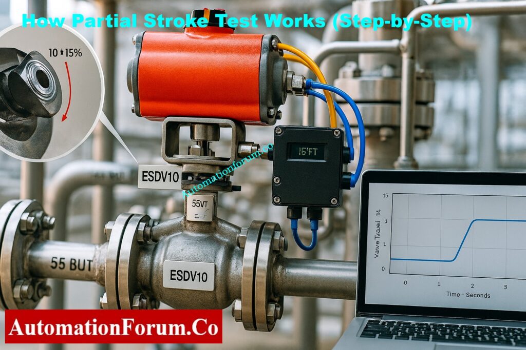
Partial Stroke Testing (PST) uses smart valve positioners with built-in diagnostics that accurately regulate and measure how the valve moves. The Dynamic Ramp Method is the most common way to make modern safety systems work. It makes sure that motion is smooth, data is collected accurately, and the process is disturbed as little as possible.
Step 1. Test Initiation:
The operator can start the PST by hand using the control system interface, or it can start automatically depending on a timetable set up in the logic solver or asset management system. This flexibility lets you check things regularly without having to stop the workflow or isolate repairs.
Step 2. Setpoint Ramp Generation:
When the intelligent valve positioner is triggered, it sends a small, controlled ramp signal to the actuator, telling the valve to move a short distance, usually 10–15% of its total stroke. This small range of motion makes sure that the valve doesn’t stop the flow of the process or put the plant’s safety at risk.
Step 3. Position and Pressure Monitoring:
While the ramp is moving, the system uses a non-contact Hall Effect sensor or a similar feedback mechanism to keep an eye on the valve’s real location. At the same time, the pressure of the pneumatic actuator is measured to see how well and reliably the valve responds to control signals.
Step 4. Return to Normal Position:
When the valve reaches the set partial stroke limit, the positioner automatically tells it to go back to the completely open or closed position, depending on how it normally works. To avoid pressure shocks or process disturbances, the changeover is done smoothly.
Step 5. Data Logging and Analysing:
The smart positioner keeps track of things like position, time, actuator pressure, and travel deviation over the whole test cycle. This information is used to make a valve signature graph, which shows how well the valve works under test settings.
You can find problems early, such slow reaction, too much friction, stiction (static friction), hysteresis, or too much actuator pressure. These problems usually mean that something is worn out, partially blocked, or leaking air, which gives maintenance workers time to fix them before a full-stroke demand or process halt happens.
PST’s automated, non-intrusive technology allows for continuous checking of the health and safety performance of valves without stopping the process. This makes sure that IEC 61511 is followed and that proof tests for Emergency Shutdown (ESD) valves are more thorough.
Select Valves for Harsh Conditions: Control Valve Selection and Recommended Practices for Harsh Process Conditions
Typical Partial Stroke Range
The extent of valve travel during Partial Stroke Testing (PST) is intentionally restricted to ensure that normal process conditions remain stable and that there is no interruption or upset to production. The goal is to test the mechanical integrity and responsiveness of the valve and actuator without allowing the valve to reach a position that could alter process flow or pressure significantly.
Common Stroke Configurations (10–15%, 5–10%)
- 10–15% Stroke: This range is usually used for conventional on-off process valves that control liquids, gases, or steam in non-critical loops. It moves enough to check the actuator torque, stem friction, and response time without changing the flow rate of the process.
- 5–10% Stroke: A lower stroke range is chosen for systems that deal with high-pressure applications, critical utilities, or very sensitive process loops. This lowers the chance of pressure spikes, flow problems, or stress on equipment, especially when even a small movement of the valve can change the balance of the operation.
Must-Have Control Valve Accessories: Essential Control Valve Accessories for Reliable Process Control
Factors Influencing Ideal Stroke Range
There are a number of engineering factors that go into finding the best partial stroke percentage:
- Process Type:
Continuous processes, like refineries or chemical plants, usually employ smaller strokes to keep the operation stable. Batch operations, on the other hand, may tolerate slightly bigger movement windows during non-critical phases. - Valve Size and Actuator Power:
To get quantifiable movement, bigger valves with higher torque actuators may need smaller relative stroke percentages. This is because too much travel could cause undesired flow changes. - Acceptable Process Fluctuation:
The process’s ability to handle small changes in flow or pressure is very important. In systems that are very carefully controlled, a movement of about 5% may be the most that can happen. In systems that are less sensitive, a movement of up to 15% is possible. - Valve Design and Service Conditions:
The right stroke limit for reliable testing also depends on the type of valve (ball, butterfly, or globe), the service medium (liquid, gas, or slurry), and the temperature and pressure at which it works.
A small movement of the stem, even only a few millimeters, can show that the valve works, the seal is good, and the actuator responds. This makes sure that the valve will work as predicted during a full-stroke demand in an emergency, without putting the plant at risk during routine checks.
Find Control Valve Stroke Length: Control Valve Stroke Length Calculator
Types of Partial Stroke Testing
Depending on the extent of automation in the plant and the technology that is available, there are many ways to set up a PST
| Type | Description | Application |
| Mechanical PST | Manual device with a mechanical limiter or handle to restrict movement | Low-cost installations |
| Electro-Pneumatic PST | Uses solenoid valves and limit switches for partial actuation | Semi-automated systems |
| Digital PST (Intelligent Positioner) | Fully automated test with feedback and diagnostics | Most modern plants |
| Remote PST | Performed remotely via DCS or control system | Offshore and hazardous zones |
Digital PST systems are the most dependable and commonly used because they work well with HART, FOUNDATION Fieldbus, and Profibus communication protocols for diagnostic monitoring.
Refer the below link for the Stroke checking procedure of control valve
Benefits of Partial Stroke Testing
Partial Stroke Testing makes safety, dependability, and maintenance more effective in measurable ways.
Safety and Reliability Benefits
- Detects Stuck Valves: Finds mechanical blockages before they cause a failure.
- Ensures Valve Movement: Checks if the actuator works and the signal is clear.
- Lessens Failure Probability: Finds up to 70% of common valve problems early on.
- Keeps the process safe: Checks to see if the valve is ready without shutting it down.
Maintenance and Operational Benefits
- Predictive Maintenance: Looks at test data to figure out how valves are likely to wear down over time.
- Optimized Shutdown Planning: Lengthens the time between full maintenance turnarounds.
- Spare Parts Management: Lets you order important spare parts on schedule.
- Reduced Labor: Automated testing cuts down on the requirement for manual examination.
Economic Benefits
- No Process Downtime: PST can be done while the process is running normally..
- Lower Testing Cost: No need for extra bypass or isolation systems.
- Better availability of equipment: keeps the plant running smoothly.
In brief, PST guarantees that valves will work with the least amount of money spent and the most effort spent.
Equal Percentage Flow Calculator: Equal Percentage Control Valve Flow Calculator
Diagnostic Parameters in a Partial Stroke Test
Smart positioners today record useful diagnostic data during each PST. Some common parameters are:
| Parameter | Description | Purpose |
| Valve Position | Actual valve travel vs. commanded movement | Checks stem response |
| Actuator Pressure | Air pressure needed to move the valve | Detects air leaks or sticking |
| Response Time | Time taken to complete partial movement | Indicates sluggishness or blockage |
| Load Factor | Ratio of actuator pressure to stem movement | Detects friction or internal wear |
Engineers use this information to make valve health reports and compare past results to see how performance has changed over time.
Control Valve ITP Download Here: Inspection and Test Plan (ITP) for Control Valves
Standards and Guidelines for PST
PST can be used with many different control and shutdown systems, but there are a number of international standards that spell out what is expected of functional valve testing.
Key References:
- IEC 61511: Sets the standards for test intervals, proof tests, and diagnostic coverage for process control applications.
- ANSI/ISA 84.00.01: This is a North American standard that is in line with IEC 61511 and gives advice on how to test and validate automation.
Understand Split-Range Valve Control: Understanding Control Valve Functions in Complementary, Exclusive and Progressive Split-Range Control Systems
Interpreting PST Results

Engineers look at the test curves after each Partial Stroke Test to figure out how the valve works.
A healthy valve signature has a smooth ramp-up and return curve, steady actuator pressure, and timing that can be repeated.
Abnormal signatures may mean:
- Delayed reaction (there may be a problem with the actuator)
- Pressure that doesn’t follow a regular pattern (air leaks or mechanical friction)
- Too much load factor (sticking or rusting)
- No movement (the valve is stuck or the signal is broken)
By looking at these results over time, maintenance staff can figure out when a valve needs to be fixed or replaced.
Refer the below link for the Control Valve ISO Calibration Procedure
Limitations and Drawbacks of PST
Partial Stroke Testing has some pros and downsides that should be thought about before it is put into use.
1. Risk of Accidental Shutdown
If set up wrong, a PST may make the valve close all the way, which would stop production by accident.
Solution: The positioner should have position limiters and soft-stop control logic.
2. Process Sensitivity
In operations with very tight control margins, even a 5% valve movement can change the flow or pressure.
Solution: Do PST when the system is stable or when the load is low.
3. Limited Fault Detection
PST can’t find all kinds of failures, such leaks in the seat or problems with the whole stroke.
Solution: Use PST together with full stroke testing every now and then during significant shutdowns.
4. Operator Hesitation
Some operators are afraid about unscheduled journeys and don’t want to employ PST.
Use certified smart positioners that include fail-safe testing modes and teach the people who work in the control room.
Recommended PST Frequency
How often you do a Partial Stroke Test depends on:
- Valve criticality
- Failure history
- Process importance
Typical guidelines suggest:
- Monthly testing for high-risk valves
- Quarterly or semi-annual testing for moderate service
- Annual testing for less critical valves
To keep track of everything, every PST should have a date, valve ID, operator name, test result, and comments written down.
Example: PST in a Refinery Shutdown Valve
Think about a refinery feed isolation valve that stays open while the plant is running normally.
The plant’s control system sets up a PST every month:
- The valve positioner moves it 15% toward closed.
- The movement time and actuator pressure are recorded.
- The valve returns to open position automatically.
- The diagnostic software flags a slight delay in closing movement compared to the previous test.
- Maintenance is scheduled to inspect the actuator, preventing future failure.
This straightforward example demonstrates how PST guarantees valve dependability while preventing process interruption.
Future Trends in Partial Stroke Testing

As digital instruments get better, PST systems are getting smarter and more integrated.
Emerging trends include:
- wireless PST monitoring for installations that are far away.
- Cloud-based diagnostic tools and maintenance dashboards that are all in one place.
- AI and predictive analytics for figuring out problems before they happen.
- Integration with Asset Management Systems (AMS) for full tracking of equipment health.
These improvements turn PST from a simple test of valve movement into a powerful tool for predicting maintenance and reliability.
The Partial Stroke Test (PST) is a very useful and cost-effective approach to make sure that important valves in process plants are ready to work. Engineers can see early indicators of mechanical failure, actuator malfunction, or signal problems by moving the valve a little bit without stopping the process.
When applied consistently, PST offers:
- More safety and dependability
- Less time spent on repairs and downtime
- Better performance and availability of equipment
Partial Stroke Testing is still one of the most useful techniques for making sure that valves work properly in modern industrial automation, whether they are employed in shutdown systems, control valves, or isolation applications.
Top Control Valve Excel Tools: Top Essential Control Valve Calculators and Excel Tools for Instrumentation Engineers
Partial Stroke Test (PST) Checklist – Excel Template
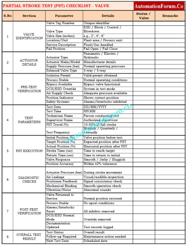
The Partial Stroke Test (PST) Checklist makes sure that important on-off or emergency shutdown valves are checked for performance on a regular basis without stopping the process. This list gives you a way to write down important information about valves, test setups, observations, and follow-up activities in an organized way. It helps maintenance and reliability teams follow IEC 61511 / ISA S84 safety rules and makes sure that all field devices have the same documentation.
Test Your Expertise with Advanced Control Valve Troubleshooting Quiz
Refer the below link to test your expertise with our Advanced Control Valve Troubleshooting Quiz for Process Control Engineers
FAQs on Partial Stroke Test (PST)
What is a PST test?
A Partial Stroke Test (PST) pushes a valve 5–20% of the way to assess how the actuator responds and how the valve moves without stopping the procedure.
What is a partial stroke test?
A PST is a test that checks the safety and control valves while the plant is running normally to see if they are sticking, causing friction, or having actuator problems.
What is the full form of PST test?
Test for Partial Stroke.
What is PST for on-off valve?
It makes guarantee that on-off valves (ESD or block valves) can move safely during an emergency shutdown.
What is the purpose of a Partial Stroke Test?
- Verify valve movement
- Detect mechanical or actuator issues
- Reduce downtime
- Improve safety proof test coverage
How often should PST be performed?
- High-risk valves: Monthly
- Moderate: Quarterly or semi-annual
- Low-critical: Annually
Can PST replace Full Stroke Testing?
No. PST finds about 70% of problems, however FST is needed for comprehensive integrity tests.
What type of valves can be tested using PST?
- ESD valves
- Block/isolation valves
- On-off and control valves with actuators
What standards govern Partial Stroke Testing?
- Functional safety according to IEC 61508
- IEC 61511: test intervals and proof testing for SIS
- ANSI/ISA 84.00.01 is a set of rules for North American SIS.
 is, how it works, its benefits, types, and IEC standards for shutdown and control valves in process industries.)