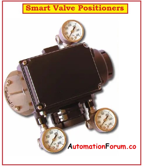
- The smart valve positioners are digital valve controllers.
- The microprocessor based smart valve positioners with internal logic and advance diagnostics.
- To operate a valve these valve positioners are designed to convert a current signal to a pressure signal.
- These provide fast and accurate positioning of diaphragm or cylinder actuators.
- The smart valve positioner produces the pressure signal for positioning the control valve according to input signal of 4 to 20 mA sent by the controller.
- This smart positioner has automatic configuration & calibration ability.
- Through DCS, PLC, and PC Software these valve positioners performs faster diagnostics.
- A diagnostics data includes installation data, calibration leak detection, performance parameters data, history data etc.
- The positioner built-in micro-processor optimizes the process performance and provides unique functions such as auto calibration, PID Control, and HART protocol communications.
- When compared to mechanical valve positioners these valve positioners achieve superior position control.
- It has an ability to embed the software commands into the memory of these smart digital controllers and represents the actual difference between digital and analog input devices.
- It allows two way communications for the process, valve, and instrument diagnostics.
What are smart valve positioners?
- Smart valve positioners are the devices that allow us to accurate throttle the control valve at a desired set point.
- Many styles and models are available depending upon the type of control valve that we are using.
- Every valve positioners requires input signal and feedback signal for accurate operation.
- An input signal is a control signal that provides a set point to valve positioner.
- Feedback signal is the signal that indicates the existing position of the valve stem.
- Input signal is provided by a pneumatic control signal to bellows.
- As input increases the bellows gets expanded and acts on the beam.
- The beam pivots and moves a flapper in relation to the nozzle.
- As the flapper position changes the nozzle pressure also changes and operates a pneumatic relay.
- At this point we simply have a pressure to pressure transducer for the input.
- The feedback element or feedback signal is very essential to convert it to positioner.
- The feedback signal ensures that the control valve is responding to the input.
- The valve positioner now corresponds to the given input signal.
- Here the feedback signal is provided by the control valve to the positioner by mechanical components.
- The CAM attached to the arm rotates as the valve strokes.
- The feedback also acts as on the beam and is an opposing force to the input signal in the bellows.
- If an increase in input is made to the device nozzle as nozzle and output pressure increases.
- The valve moves and feedback from the CAM acts on the opposite side of the beam moving the flapper away from the nozzle.
- Here the beam is considered as a summing component.
- Both the input and feedback are applied to the summing beam and are constantly compared to each other.
- If the forces are equal the nozzle and flapper relationship remains stable and the output pressure from the device remains constant.
- The valve position is then maintained if there is a change to one of the forces occurs the flapper is again adjusted in a relation to the nozzle and output.
- If the valve positioner is calibrated properly the valve position will correspond to a given control signal.
- Let us consider a pneumatic control signal of 3 psi to 15 psi as an input signal then for
| Signal | Valve Position |
| 3 PSI | The valve gets fully opened for 0% |
| 9 PSI | The valve opens for only 50% |
| 15PSI | The valve gets fully closed for 100% |
- The positioner gives the control valve the ability to overcome valve friction and process forces that may cause position deviations. As there are many advantages of using a smart valve positioners.
- Accuracy positioners are selected to achieve throttling control of piston actuators to accommodate non compatible control signals.
- To ensure proper shut off the control valve to enable split ranging and to change the gain characteristics of the control valve.
- The smart positioners perform the basic functions as analogue positioners are combined with current to pneumatic converters.
Specifications of smart valve positioners:
| Sl no | Parameters | |
|---|---|---|
| 1 | Input | 2-wire, 4-20 mA |
| 2 | Output | 0 -100% supply air pressure, Single /Double action |
| 3 | Output Capacity | 13.6 Nm³/h at 5.6 bar |
| 4 | Power Supply | 4-20 mA current |
| 5 | Configuration | Remote configuration using HHT |
| 6 | Pressure Supply | 1.4 – 7 bar |
| 7 | Actual Position Sensing | Magnet via Hall effect |
| 8 | Indication | LCD indicator |
| 9 | Material | copper aluminum316 stainless |
| 10 | Temperature | -40 to 85ºC |
| 11 | Humidity | 0 to100 Optional % RH |
| 12 | Hazardous Area | Explosion and weather proof. |
| 13 | Weight | 2.7 kg |
Advantages of smart positioners:
- These have automatic calibration and configuration.
- Save time in making traditional zero and span setting.
- The valve diagnostics can be done through the distributed control systems, PC software tools, or handheld communicators,
- Control valve health can be diagnosed easily even in the line.
- Cost of loop commissioning is reduced.
- Accuracy of the process is improved.
How does valve positioners works?
A valve positioner is a device that interfaces with actuator and process controller. This is connected to the valve stem to sense the exact position of the valve.
The process controller sends an electric signal to valve positioner and outputs proportional signal to the actuator to operate the valve stem for opening and closing of the valve.
Which are the types of valve positioners?
There are 3 types of positioners:
- Pneumatic valve positioner.
- Electro-pneumatic (EP) valve positioner.
- Digital valve positioner.
What is electro pneumatic valve positioner?
An electro-pneumatic valve positioner’s converts electric signal 4-20mA to a proportional pneumatic signal 3 to 15 PSI.
These when used with rotary air actuators to position the control valves accurately in throttling applications.
Is hydraulics are faster than pneumatic?
Hydraulic systems can lift heavy materials due to incompressibility of oil and with larger size. But hydraulic system is slower than pneumatic systems due to higher viscosity of working fluid in the system that requires more energy for movement in the pipe.
Are pneumatic systems better than hydraulic systems?
Yes, in every industrial environment that uses both hydraulics and pneumatics systems. The pneumatic systems are safer than hydraulics, because the pneumatic is not corrosive or poisonous and leakage of air will not cause any contamination.
Where are valve positioners used?
The valve positioners are used to position the valve stem of the control valve where we require accurate and rapid control without any hysteresis.
In linear sliding stem control valves the valve positioners are generally mounted on the side yoke or top casing of the pneumatic actuator.
In rotary control valves the valve positioners are mounted near the end-of-shaft.