Rectifier
The rectifier job is to change incoming AC from a transformer or other AC power source into a pulsing form of DC. In other words, it changes current that alternately flows in both directions so that the output current only flows in one direction. The circuit needed to perform this could be as simple as a single diode, or it could be much more complicated.

All rectifier circuits can be divided into one of the following two groups: Half Wave rectifier & Full Wave Rectifier
Half-Wave Rectifier
Rectifiers allows half of the AC cycle to complete while blocking current to stop it from flowing during the other half of the cycle will convert AC to pulsating DC. The output is displayed in the figure to the right. Because they only utilize half of the incoming AC wave, such circuits are referred to as half-wave rectifiers.
Full-Wave Rectifier
Using two and four diodes, the full wave rectifier turns the two halves of each waveform cycle into a pulsing DC signal. Four rectification diodes are used by the full wave rectifier to transform each waveform cycle’s two halves into a pulsing DC signal.
Half Wave Rectifier
The simplest rectifier circuit consists of a diode connected in series with the AC input. The output of the rectifier will only receive half of the incoming AC wave because a diode only allows current to flow in one way. Thus, this is a straightforward half-wave rectifier.
It is important to consider the diode’s orientation since, in the example, it only passes the positive half-cycle of the AC input, resulting in a positive DC component in the output voltage. If the diode were to be turned around, the negative half-cycle would be passed in its place, and the output’s DC component would be polarised negatively.

Full wave Rectifier
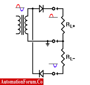
- It is also very feasible to combine two half-wave rectifiers.
- This configuration offers both positive and negative output voltages, using half of the input AC cycle for each output.
- Make note that the lower transformer connection always serves as the output’s common reference point.
- It usually has a connection to the circuit’s common ground.
- In some situations, this may be crucial.
- Of course, the iron core of the transformer is electrically isolated from the windings, and that core is typically grounded by virtue of being physically fastened to the metal chassis (box) that houses the complete circuit.
In order to prevent this winding from ever experiencing even brief voltages that could overload the insulation and harm the transformer, we also ground one end of the secondary winding.
Centre Tapped Full-Wave Rectifier
The half-wave rectifier is relatively simple and functional, although it isn’t very effective. It wastes all of the energy present in the remaining half of the incoming AC cycle and only utilizes half of it. We would like to be able to use both half of the incoming AC for increased efficiency. One approach to do this is to double the secondary winding’s size and connect it to the middle of the winding. Thus, to enable full-wave rectification, two independent half-wave rectifiers can be used on alternate half-cycles. To the right is a diagram of the circuit.

Similar to the half-wave rectifier, this rectifier design necessitates grounding one of the secondary leads of the transformer. But, in this instance, the center connection, often referred to as the center tap on the secondary winding
Moreover, it is entirely feasible to employ two full-wave rectifiers to obtain outputs of both polarities simultaneously, as seen to the right. Both half of the AC cycle are transmitted by the full-wave rectifier to either a positive or negative output. As a result, the output has access to more energy without experiencing lengthy stretches of zero energy.
Full-wave rectifiers are therefore more effective than half-wave rectifiers. A full-wave rectifier, on the other hand, requires a secondary winding that is twice as large as the secondary of a half-wave rectifier since only half of the secondary winding is supplying power on any given half-cycle of the incoming AC.

Full-Wave Bridge Rectifier
A single transformer winding’s AC output can be rectified fully using the four-diode rectifier circuit, as shown to the right. The resistor configuration of a Wheatstone Bridge is the same as the diamond configuration of the four diodes.
In fact, any combination of components in this form is recognized as a bridge of some kind, and the rectifier circuit is also referred to as a bridge rectifier.

The connections to the diodes in this circuit and in the dual-polarity full-wave rectifier above are identical.
The secondary winding’s center tap has been deleted, and we are now using the negative output as our ground reference instead. This is the only modification.This means that the secondary of the transformer is never directly grounded, but is instead always brought close to ground by a forward-biased diode at one end or the other.
Advantages, Disadvantages & Application of rectifier
Half-wave rectifiers Advantages
- Simple circuit with few components.
- Inexpensive in the beginning. Despite the fact that there is an increased cost over time from more power losses
Half Wave Rectifier’s Disadvantages
- Converts only one cycle of the sinusoidal input given to it and the other cycle goes squandered, resulting in increased power loss.
- The output current so obtained is not entirely DC and it still contains a lot of ripple. HWR creates lower output voltage (i.e. it has a high ripple factor)
Applications of Half Wave Rectifiers
- Because its main flaw is that its output amplitude is lower than its input amplitude, the half-wave rectifier is typically employed in low power applications.
- Powering Appliances
- Transformer use and Soldering
- Pulse-generated circuits & Single demodulation
- Voltage multiplier, AM radio
Full Wave Rectifiers Advantages
- The full-wave rectifier efficiency is higher than half-wave rectifier.
- Both cycles are being utilized. Hence, there is no output power loss.
- As both cycles were applied to the rectification. The input voltage signal won’t be lost, and the ripple factor is lower than that of a half-wave rectifier.
- A higher mean DC value is attained.
- The bridge rectifier is more affordable than the center-tapped full-wave rectifier because the center-tapped is more expensive.
Full wave Rectifiers Disadvantages
- The expense of the center-tapped transformer used in this circuit is the only drawback. Bridge rectifier circuits are built using the four diodes coupled in a bridge topology to address this drawback.
- It is challenging to find the secondary’s tapping centre.
- It costs a lot to produce.
Application of Full wave Rectifiers
- The full-wave bridge rectifier circuit is used to measure the amplitude of the modulating radio signal.
- This circuit is employed in electric winches to supply constant DC voltage in a polarised manner.
- This rectifier circuit, which is a component of the power supply unit in many appliances, has a high rectification efficiency.
- It is able to transform high AC voltage into low DC value.
- They are employed when powering up items like motors and LED lighting
- Laptops, Mobile devices, and Charger circuits.
- Circuits for an uninterruptible power supply (UPS) convert AC to DC.
- The inverters in our homes convert AC to DC, LCD and LED Televisions.