
- Understanding Control Valve Passing and Why It Happens
- What Does It Mean When a Control Valve Is Passing?
- How a Control Valve Should Close Under Normal Conditions
- Common Symptoms of a Passing Control Valve
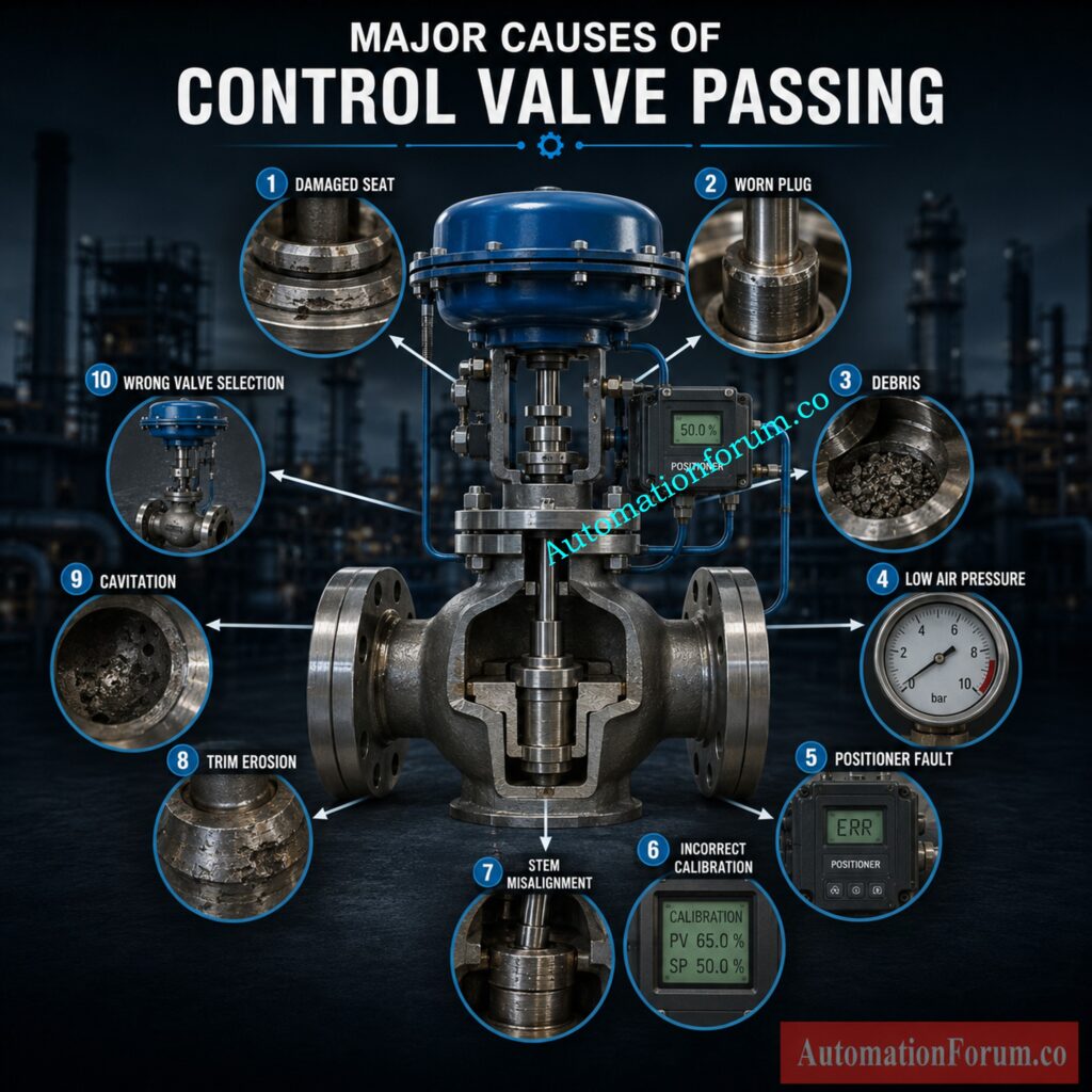
- Major Causes of Control Valve Passing
- Control Valve Shutoff Performance by Valve Type
- How to Troubleshoot a Passing Control Valve
- Field Diagnostic Techniques for Detecting Control Valve Passing
- Control Valve Leakage Classes Explained
- Real Industrial Example of a Passing Control Valve
- Key Takeaways on Control Valve Passing and Troubleshooting
- Frequently Asked Questions on Control Valve Passing
Understanding Control Valve Passing and Why It Happens
One of the most prevalent and expensive difficulties in industrial process facilities is a control valve that continues to pass fluid after it has reached the closed position. Whether it is controlling steam, water, gas, chemicals or slurry, partial cutoff can impact production quality, lower energy efficiency and cause significant operational problems. Operators may observe unpredicted temperature spikes, pressure increases, or continuous flow when the control system shows the valve at zero percent open.
Many engineers jump to the conclusion that the valve has failed and order a replacement. In truth, the valve is typically just hiding the symptom of another underlying disease. Problems with the actuator, positioner, air supply, valve trim, process conditions or improper valve sizing might cause improper cutoff.
The key is to find the fundamental cause; replacing a healthy valve without thorough diagnosis increases maintenance expenses and extends downtime without solving the original problem. A methodical troubleshooting methodology helps engineers to discover the real defect, restore dependable operation, and improve overall process performance.
This page describes why control valves continue to pass fluid after being closed, the most common causes, practical field symptoms and established troubleshooting approaches used in industry operations.
Refer the below link for the What are the main causes of control valve hunting?
What Does It Mean When a Control Valve Is Passing?
A control valve moves a plug, ball, disc or gate against a sealing surface to open or close to control or stop the flow of a process. When the valve reaches the complete closed position the process flow should go down to the permitted leakage stated by the valve manufacturer or the industry standards.
But many engineers use the word passing when fluid is still flowing through a valve that should be closed.
There are several sorts of leaking that you will see often.
Internal Leakage
Internal leakage is the flow of fluid through the valve seat in spite of the valve being fully closed. This is the most common reason engineers describe a valve as “passing.” Damaged seating surfaces, worn trim, or debris trapped between the seat and plug are typical causes.
Seat Leakage
Seat leakage specifically refers to leakage across the sealing surfaces inside the valve. Every valve has an allowable leakage limit depending on its shutoff class. A small leakage within the standard is okay, but an excessive leakage signals a fault.
Prevent Calibration Problems with Correct Actuator Bench Set Practices: Why is Control Valve Actuator Bench Set Important ?
Body Leakage
Body leakage is leakage of process fluid through the valve body caused by fractures, casting defects or broken body gaskets. Unlike seat leakage, it leaks to the outside environment rather than through the valve.
External Leakage
External leakage occurs around packing glands, bonnet joints, flange connections, or instrument fittings. Although serious, it is different from internal valve passing because it does not involve flow through the closed valve.
It is important to understand that no standard control valve is completely leak free unless specifically designed for bubble tight shutoff. International leakage standards define acceptable leakage rates based on valve design and application. Engineers should compare actual leakage with the specified shutoff class before concluding that the valve has failed.
Finally Eliminate Persistent Valve Oscillation Before Production Suffers: Control Valve Hunting Due to PID Controller: Causes, Effects, Root Analysis and Complete Troubleshooting Guide for Industrial Process Control Systems
How a Control Valve Should Close Under Normal Conditions

Control Valve Closing Sequence
If you understand the regular closing sequence it helps engineers determine where things go wrong.
When the process controller commands the valve to close, the positioner receives the command and changes the actuator pressure. Depending on the design of the actuator, the actuator stem is moved downwards or upwards by air pressure or by spring force.
The actuator transmits this movement to the valve stem, moving the plug toward the seat ring. The sealing surfaces form a tight barrier to stop process flow when the plug meets the seat.
Importance of Proper Seating Force
In the last step of travel the actuator must produce sufficient force to overcome process pressure and positively seat the plug. If the closing force is too low, leakage may continue even after the valve position indicator reads zero percent.
The final seating force in the case of spring return actuators is provided by the spring in fail safe operation. Air powered actuators need instrument air pressure so that they have appropriate travel. Ball valves and butterfly valves are examples of rotary valves . They use the torque of the actuator to rotate the closure element to the fully closed position .
Final Valve Travel and Tight Shutoff
Within the valve, the last few millimetres of travel are the most essential. Even slight damage to the plug, seat ring, or stem alignment can hinder proper sealing and allow continued process flow.
Diagnose Unresponsive Control Valves Faster with Proven Field Methods: Field Troubleshooting Guide: Control Valve Not Responding in Process Area
Common Symptoms of a Passing Control Valve
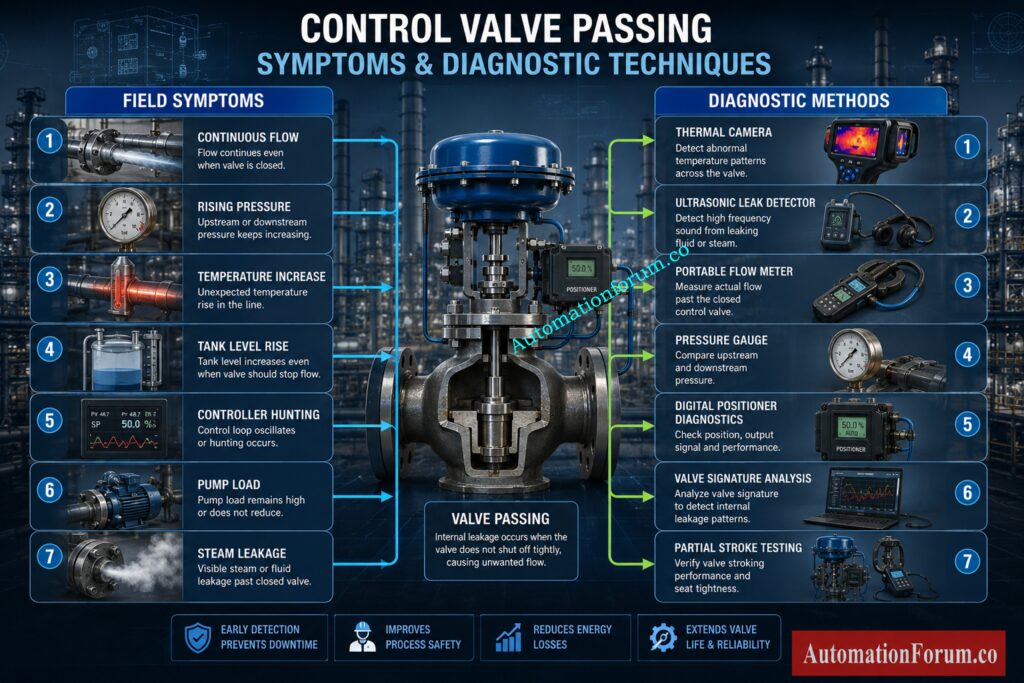
Recognizing field symptoms can allow engineers to discover valve passage before it causes major production losses.
Process Flow Continues After Valve Reaches Zero Percent
The most visible indication is a constant flow when the controller is commanding the valve fully closed. Flow indicators may suggest a low flow rate, which is always more than zero.
Pressure Continues Increasing
In pressure control or isolation, downstream pressure may continue to increase after the valve is shut. This generally means seat leaking or no shutoff.
Tank Level Rises Unexpectedly
In pressure control or isolation, downstream pressure may continue to increase after the valve is shut. This generally means seat leaking or no shutoff.
Temperature Does Not Reduce
Steam control valves with internal leaks nevertheless transport heat to exchangers, reactors or process lines. This means that the temperatures stay above the desired operating point even with the valve fully closed.
Stop Expensive Valve Failures Using These Proven Engineering Practices: Control Valve Body Material Selection Guide for EPC Design Instrumentation Engineers
Pumps Continue Operating Under Load
A passing relief valve admits undesired flow that prevents the pumps from unloading effectively. Typical results are increased power usage and excessive wear on equipment.
Compressors Fail to Unload
Poorly closed gas control valves may allow compressors to stay loaded longer than planned, lowering efficiency and raising operating costs.
Continuous Steam Heating
A little seat leakage in steam systems can add up to a lot of heat energy. Operators can see steam traps cycle continually or equipment remain hot long after shutdown.
Process Instability
Valve passing means uncontrolled flow into the process and leads to changes in pressure, temperature or flow which are hard for the control system to stabilize.
Controller Hunting
Since the process never reaches the target state, the controller will keep changing the valve position. Constant movement leads to wear on the valve and the actuator.
Refer the below link for the How to do maintenance on struck control valve?
Equipment Cannot Be Properly Isolated
Closed valves may allow process fluid to pass, making it impossible for maintenance staff to properly separate pipes or equipment. This leads to delays in operations and possibly safety issues.
Reduced Production Efficiency
While valve leakage may seem insignificant, persistent product loss, high steam consumption, control problems, and process adjustments eventually lead to the steady decline in plant efficiencies and the increase in operating costs.
Boost Shutdown Valve Reliability with This Critical Testing Guide: What is Partial Stroke Test (PST)? A Complete Guide for Shutdown and Control Valves
Major Causes of Control Valve Passing
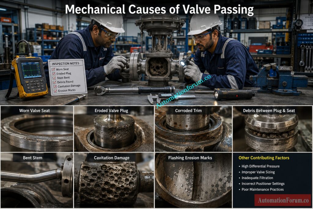
Damaged Valve Seat
What is the main sealing surface in the control valve? Valve seat. Over time, service that is continuous might cause the seat to wear, dissolve or corrode, impeding tight shutdown. The most common place where wire drawing occurs in steam systems is where high velocity steam slowly grooves the sitting surface. In slurry applications the abrasive particles impact the seat continually and the erosion increases. Other reasons for the plug not sealing correctly could be mechanical damage during maintenance or incorrect assembly.
Damaged Valve Plug
The valve plug must seal the seat tightly to stop flow. Uneven contact between plug and seat is caused by scratches, corrosion, impact damage or bent stems. Under high differential pressure, any minor surface flaw can cause significant leakage. Misalignment might be caused by worn guides or incorrect installation; this can further impair sealing efficacy.
Decode Cv and Kv Relationships for Smarter Valve Engineering Decisions: Relationship Between Cv and Kv in Control Valves
Foreign Material Between the Seat and Plug
During closure, rust flakes, welding slag, scale, sand, packing pieces or other process debris are often caught between the plug and seat. The plug never fully seats but sits on the trash and there is a leak channel . Cycling or flushing the valve will clear the obstruction in certain circumstances, but normally the problem will return until the process line is properly cleaned.
Incorrect Actuator Adjustment
The valve may not reach its designed closed position if the stem is improperly adjusted, if the travel limits are incorrect, if the mechanical stop settings are incorrect, or if the actuator thrust is insufficient. The position indicator reads zero percent, yet the plug may still be slightly above the seat, and a continual leak may occur. Accurate calibration and travel confirmation are required following maintenance or actuator change.
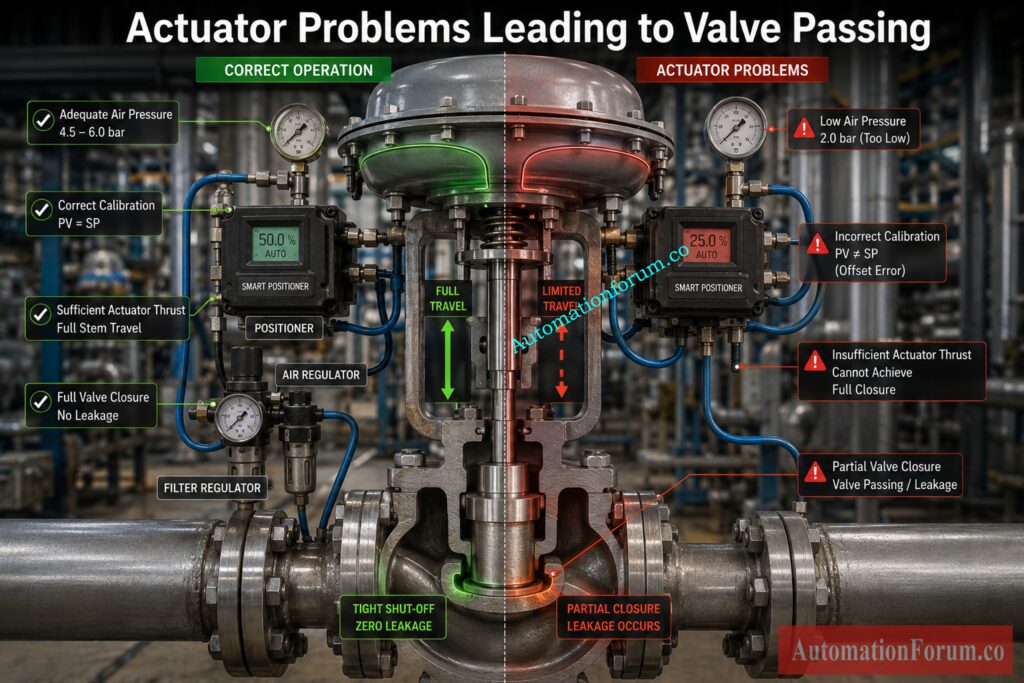
Insufficient Air Supply
Pneumatic control valves require clean, dry instrument air at the proper pressure. Low air pressure lowers the thrust of the actuator and prevents the valve from sitting correctly. Air leaks in tubing or fittings, clogged air filters, a malfunctioning regulator and moisture contamination may affect actuator operation. Engineers should not assume a valve is faulty until they have checked the air supply pressure.
Positioner Problems
If the positioner is not adjusted properly it can prematurely stop the actuator before the valve is fully closed . Worn mechanical linkages, loose feedback arms, pneumatic leaks and wrong digital positioner settings all contribute to imprecise valve positioning. Most smart positioners today save diagnostic data that can help you spot excessive friction, trip deviation or calibration drift.
Valve Sizing Problems
High Differential Pressure
The greater the pressure differential across a closed valve, the greater the force on the plug and seat. The actuator might not create sufficient seating force for tight shutdown if the valve is not made for such conditions. Some harsh service applications require pressure balanced trim or specifically constructed valves to accommodate the high differential pressure.
Cavitation and Flashing Damage
Near the vapor pressure , liquid services can encounter cavitation or flashing. Cavitation causes the formation of vapor bubbles which collapse violently on the internal valve surfaces creating severe pitting. It occurs when a liquid is permanently changed to vapor . This causes continued erosion . Both slowly erode away at the seat and plug and ultimately cause interior leaks.
Trim Erosion
High velocity process fluids containing abrasive particles constantly erode valve trim components. Trim erosion is common in power plants, mining activities and slurry handling systems. As the sealing surfaces degrade, leakage increases until the valve no longer provides satisfactory shutdown performance.
Packing Problems
The packing is supposed to seal around the valve stem . Too much packing compression can increase stem friction . High friction inhibits the stem from moving smoothly and may keep the valve from reaching its final seating position. The correct packing adjustment will ensure a reliable seal without limiting the travel of the valve.
Unlock Superior Valve Accuracy Using Advanced Positioner Technologies: Why You Should Use Control Valve Positioners?
Stem Misalignment
Bent stems, worn stem guides, severe pipe tension, or improper installation procedures can cause the plug and seat to become misaligned. Even minor misalignment hinders uniform seating and generates leakage routes. Check the guide condition and the stem straightness when overhauling valves.
Actuator Mechanical Failure
Internal mechanical faults in the actuator can greatly diminish the closing force. When springs are broken, diaphragms are ruptured, pistons are damaged, seals are worn or mechanical elements are sticking, the actuator cannot accomplish its entire stroke. A routine inspection of an actuator can catch these problems before they impede process performance.
Wrong Valve Selection
Selecting the wrong valve type for the application often leads to persistent leakage problems.
Control Valve Shutoff Performance by Valve Type
| Valve Type | Typical Shutoff Performance | Common Applications |
| Globe Valve | Excellent control and good shutoff | Steam, flow, pressure, temperature control |
| Ball Valve | Excellent isolation and bubble tight shutoff | On off applications |
| Butterfly Valve | Moderate shutoff depending on seat design | Cooling water, HVAC, utilities |
| Plug Valve | Good isolation with simple construction | Chemical and utility services |
| Gate Valve | Isolation only, not throttling | Pipeline isolation |
Using a throttling globe valve where bubble tight isolation is required, or selecting a butterfly valve for severe differential pressure service, often results in continuous valve passing.
Build Accurate Valve Datasheets That Prevent Costly Design Errors: How to Prepare Control Valve Datasheets: A Step-by-Step Procedure for EPC Instrumentation Engineers
How to Troubleshoot a Passing Control Valve
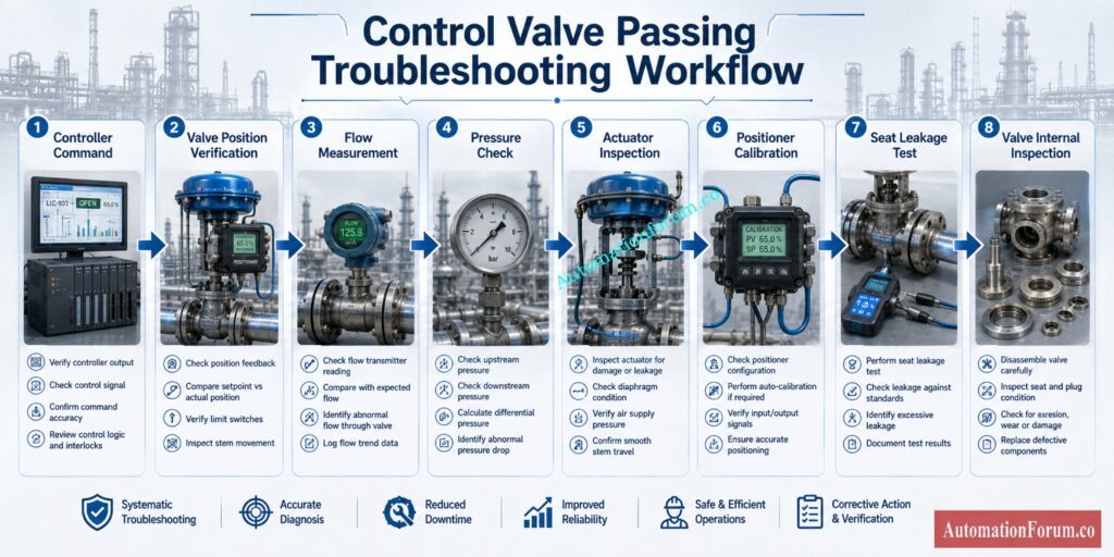
A systematic troubleshooting approach prevents unnecessary valve replacement.
- Review process trends. Examine historical flow, pressure, level, and temperature data to determine when the leakage first appeared.
- Confirm valve command. confirm that the control system is truly directing the valve to zero percent
- Check Valve Position Feedback. Check the position of the valve against the controller output. Differences may suggest difficulties with the positioner or actuator.
- Measure in use flow. Do not rely just on valve position. Check for leaks using the process flow meter or a portable flow meter.
- Check upstream and downstream pressure Abnormal pressure circumstances can imply too much differential pressure or unanticipated process modifications.
- Verify actuator travel. Check that the actuator moves smoothly to its mechanical stop without sticking or hesitating.
- Do a stroke test. Slowly cycle the valve through its full trip checking for smooth operation .
- Check the instrument air pressure. Measure the supply pressure to the actuator while the valve is moving.
- Check the positioner. Calibration verification Link condition Air leaks and diagnostic warnings
- Perform a seat leakage test Compare measured leakages with shutdown class of valve as given.
- Check-valve internals. During shutdown check the plug, seat, stem, guides and trim for wear or damage.
- Check valve sizing, process conditions. Confirm that the valve is suitable for current operating conditions and required shutoff performance.
Field experience shows that combining process data with physical inspection usually identifies the true root cause much faster than replacing components one by one.
Choose Valves That Survive the Harshest Industrial Process Conditions: Control Valve Selection and Recommended Practices for Harsh Process Conditions
Field Diagnostic Techniques for Detecting Control Valve Passing
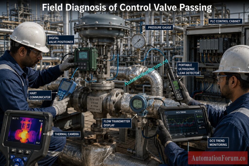
Modern plants use several diagnostic methods to confirm internal valve leakage.
- Pressure gauges reveal unexpected pressure changes across a closed valve.
- Leaking steam valves can be detected using temperature readings which show unwanted heat transfer.
- Portable flow meters are used to verify that fluid continues to flow after a valve is shut.
- An ultrasonic leak detector listens for the high-frequency sound that is produced by an interior leak.
- Thermal cameras detect hot regions and can immediately find faulty steam valves.
- Valve signature analysis evaluates the features of friction, seating force and travel.
- Digital valve controller diagnostics indicate travel deviation, hysteresis and excessive friction.
- Partial stroke testing confirms the actuator is moving without stopping the plant.
- Acoustic monitoring detects the noise from a leak before it shows up in the process measures.
- Vibration analysis can detect aberrant mechanical behavior induced by the unstable operation of valves.
- Online condition monitoring provides continuous monitoring of valve health and facilitates predictive maintenance strategies.
Upgrade Valve Reliability with Must-Have Performance Enhancing Accessories: Essential Control Valve Accessories for Reliable Process Control
Control Valve Leakage Classes Explained
| Leakage Class | Allowable Leakage | Typical Applications | Typical Valve Type | Shutoff Performance | Common Industries |
| Class II | Small allowable leakage | General process control | Globe valve | Moderate | Chemical plants |
| Class III | Lower leakage than Class II | Standard process service | Globe valve | Good | Oil and gas |
| Class IV | Common industrial shutoff | Process control | Globe valve | Very good | Refineries |
| Class V | Very low leakage | High pressure service | Globe valve | Excellent | Power plants |
| Class VI | Bubble tight shutoff | Critical isolation | Soft seated valves | Outstanding | Pharmaceutical, food, specialty chemical |
Higher leakage classes require tighter manufacturing tolerances and better sealing surfaces. Engineers should always verify the specified leakage class before concluding that a valve is defective, since some leakage may still comply with the manufacturer’s design standard.
Understand Critical Valve Metrics Every Instrumentation Engineer Must Know: Essential Control Valve Performance Parameters
Real Industrial Example of a Passing Control Valve
Process Problem
A refinery had inconsistent reactor temperature because a steam control valve was continuously showing zero percent opening. The temperature of the reactor continued to increase during low output hours, even with the closed valve position.
Root Cause Investigation
The operations team first thought the problem was due to inadequate controller tuning and altered the control loop many times. But the question of the temperature remained. Instrument technicians confirmed that the positioner calibration, actuator travel and instrument air pressure were all in spec.
Inspection Findings
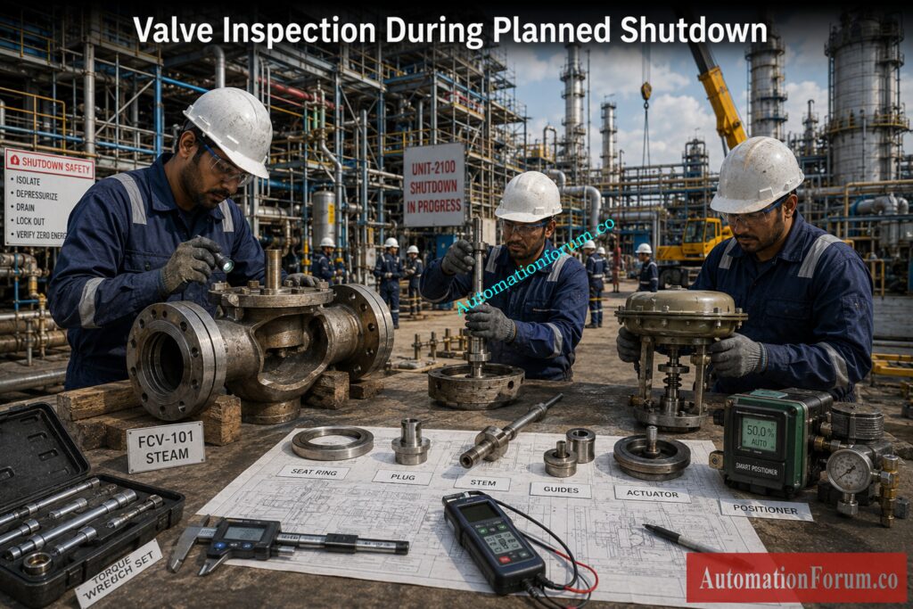
The valve was removed for inspection during a scheduled outage. Engineers found the valve plug and seat to have extensive cavitation damage. The constant erosion had worn microscopic grooves which permitted steam to pass even with the valve pulled all the way to closed.
Corrective Action
The damaged trim was replaced with a cavitation resistant design more suitable for the working conditions. After installation, seat leakage testing confirmed that the valve achieved the required shutoff class. Reactor temperature stabilized, unnecessary steam consumption decreased, and process control returned to normal.
Solve Difficult Actuator Problems Before They Cause Unexpected Downtime: Common Challenges and Solutions for Industrial Control Valve Actuators
Results After Repair
The investigation demonstrated that changing controller settings could never have solved the problem because the actual root cause was mechanical damage inside the valve.
Master Valve Sizing Techniques to Maximize Process Performance Today: How to Properly Size Control Valves for Maximum Efficiency?
Key Takeaways on Control Valve Passing and Troubleshooting
When a control valve continues to pass fluid after it is fully closed, it is frequently a symptom rather than the actual cause of the problem. Internal leakage is often caused by damaged seats and worn trim, but similar symptoms may be caused by problems with the actuator, positioner, instrument air supply, valve sizing, process conditions or installation.
The effective troubleshooting starts with study of process data, verification of valve position, assessment of actuator function and leakage check by proper field testing before dismantling the valve. Engineers are able to identify the true defect and prevent wasteful component replacement by using operational information along with a careful inspection of the valve assembly.
By using a structured diagnostic methodology and choosing valves according to the process circumstances, facilities can increase process stability, reduce energy losses, limit unscheduled shutdowns, and extend the service life of important control valves. A well maintained and correctly applied control valve not only improves reliability but also contributes to safer and more efficient plant operation.
Avoid Sizing Errors by Understanding True Control Valve Cv: Why Measuring Control Valve Cv is Essential for Proper Valve Sizing ?
Frequently Asked Questions on Control Valve Passing
What is control valve passing?
Control valve passing is the passage of process fluid via a control valve after the valve has been fully closed. It is generally caused due to internal seat leaking or problems connected to faulty trim or actuator.
What does it mean if a valve is passing?
A passing valve signifies that the valve is not providing the required shutdown and permits fluid to seep across the seat. This might lead to instability of the process, energy losses and reduced efficiency of the equipment.
How do you check valve passing?
Valve passing is tested on the downstream flow, pressure or temperature once the valve is fully closed. Engineers might also run a seat leak test, or employ ultrasonic and thermal diagnostic equipment.
Prevent Leakage Failures with Industry Approved Valve Testing Practices: Control Valve Leakage Testing, Types, and Calculation Standards
What is the difference between PCV and LCV?
The process pressure is controlled by a Pressure Control Valve (PCV). A liquid level inside tanks, vessels or separators is controlled by a Level Control Valve (LCV). Both use distinct process variables but the control principles are similar.
Why is my control valve leaking when fully closed?
The most typical reasons are worn valve seats , damaged plugs , trapped debris , poor actuator adjustment or insufficient actuator thrust . Before changing the valve, you need to find the reason of the problem.
Can a control valve be completely leak free?
Not all control valves are meant to be zero leak. Achieving near-leak-free performance under stated conditions is possible only with bubble-tight cutoff valves, such as those meeting Class VI leakage criteria.
Can low instrument air pressure prevent valve closure?
Yes. Low pressure of instrument air results in a lower force of the actuator, which does not allow the valve to fully seat on the valve seat. This often leads to internal leakage or valve passing.
How does cavitation damage a control valve?
Cavitation causes the formation of vapor bubbles that collapse and degrade the valve plug and seat with time. This deterioration slowly increases internal leakage and decreases the valve’s shut off function.
Which control valve provides the best shutoff?
Soft seated ball valves are often the best shutdown for isolation duty. Globe control valves provide excellent flow control, but its shutdown capability is dependent on the set leakage class.
Can a faulty positioner cause valve passing?
Yeah. A mis-calibrated or failing positioner can allow the actuator to stop short of fully closing the valve. With proper calibration and verification of the position feedback this can be promptly identified.
Refer the below link for the How to Troubleshoot On-Off / Shutdown Valve
