- Introduction to S84 / IEC 61511
- What is S84 / IEC 61511 Standard?
- Key Terminology in IEC 61511
- Safety Instrumented Systems – Core Components
- Understanding Safety Instrumented Functions (SIF)
- Why IEC 61511 was Developed
- When Does S84 / IEC 61511 Apply?
- Relationship with Other Layers of Protection
- Do We Always Need SIS?
- Effectiveness of Protection Layers
- Safety Integrity Levels (SIL)
- Safety Lifecycle Requirements
- Safety Requirements Specification (SRS)
- Design & Engineering Considerations
- Testing and Validation Requirements
- Operation, Maintenance and Modification
- Decommissioning and End-of-Life
- Compliance Drivers
- Common Errors in IEC 61511 Implementation
- Best Practices
- What IEC 61511 Does and Doesn’t Do
- FAQ On S84 / IEC 61511 Standard
- Take the Quiz: Test Your Expertise in Safety Instrumented Systems (SIS)
Introduction to S84 / IEC 61511
Safety is more than just a legal requirement in the oil and gas, petrochemical, refining, pharmaceutical, power generating, and even pulp and paper industries; it is also the key to long-term business success. Catastrophic results can happen when equipment breaks down, people make mistakes, or processes go wrong in a way that isn’t usual. These things usually don’t happen very often, but when they do, the effects are really bad.
Importance of safety in process industries
Plants use a lot of different types of protection to deal with this, such as design safeguards, alarms, emergency protocols, and mechanical devices like relief valves. But when the possible outcomes include death, damage to the environment, or huge financial loss, there needs to be a dedicated system that can find dangerous situations and automatically bring the process to a safe state without needing the operator to do anything.
The Safety Instrumented System (SIS) does this. The ANSI/ISA S84.00.01-2004 / IEC 61511 standard governs the SIS. It sets forth an organized manner to design, build, test, run, maintain, and eventually retire the SIS in a way that guarantees the necessary risk reduction is achieved throughout its life cycle.
Discover: What is an Emergency Block valve and How does it work
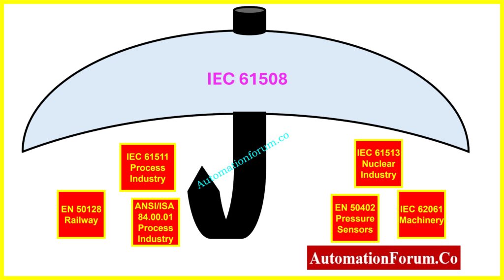
How IEC 61511 complements IEC 61508
IEC 61511 is a version of the larger IEC 61508 standard that deals with functional safety for all electrical, electronic, and programmable systems. It is specifically designed for the process industry. Most of the world now agrees that Recognized and Generally Accepted Good Engineering Practice (RAGAGEP) is the right way to do SIS.
Download Now: Functional Safety Terminology – Excel Download for Industrial Automation
What is S84 / IEC 61511 Standard?
S84 vs IEC 61511
The S84 / IEC 61511 standard is a framework that is known around the world for setting the lifecycle criteria for Safety Instrumented Systems in the process industries. It has two names:
- S84 is the ANSI/ISA standard that is used in the United States.
- IEC 61511 is the standard set by the International Electrotechnical Commission that everyone uses.
Both are in sync and have the same structure and technical content. They talk about the engineering, management, and verification steps that need to be taken to make sure that a SIS works safely over its whole operating life.
Scope and coverage
The scope of IEC 61511 covers:
- SIS that use electrical, electronic, or programmable electronic (E/E/PES) tech.
- From the idea stage to the end of the life cycle.
- Using hazard analysis methodologies like HAZOP, LOPA, and fault tree analysis to figure out when safety functions are needed and what they need to do.
IEC 61511 does not require every facility to have a SIS; it only requires that there be a risk-based reason for its use. This makes sure that SIS installations are only used when there is no alternative independent protective layer that can lower the risk to acceptable levels.
Key Terminology in IEC 61511
To understand and use IEC 61511, you need to have a good understanding of the terms used.
| Term | Full Form | Description and Industrial Example |
| SIS | Safety Instrumented System | An automated system that works on its own to find dangerous situations and automatically return the process back to a safe state. For example, the Emergency Shutdown System (ESD) on an oil platform in the ocean. |
| SIF | Safety Instrumented Function | A precise thing that the SIS does to stop a dangerous event from happening. For example, a high-pressure trip in a gas compressor that lets gas out and stops the compressor. |
| SIL | Safety Integrity Level | A performance goal (1–4) that shows how likely it is that the SIF will fail when needed. Higher SIL means more dependability. |
| BPCS | Basic Process Control System | The main system for controlling routine operation. For example, DCS controls the temperature in a reactor. |
| IPL | Independent Protection Layer | A safety measure that works on its own, without help from other levels of protection. For example, a mechanical relief valve that works even if the SIS or BPCS isn’t working. |
| LOPA | Layers of Protection Analysis | A semi-quantitative method for determining whether additional safeguards like SIS are required. |
| PFD | Probability of Failure on Demand | The chance, based on statistics, that the SIF won’t work right when needed. |
| IEC | International Electrotechnical Commission | The group that creates international safety rules like IEC 61508 and IEC 61511. |
Safety Instrumented Systems – Core Components
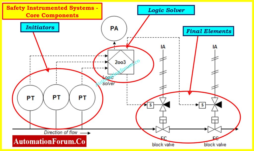
A Safety Instrumented System is not merely a safety PLC. It is a whole protective structure that includes:
- Sensors – Sensors look for signs that a process might be getting worse, which could mean a potential hazard. For example, there are temperature transmitters in a chemical reactor and level transmitters in a storage tank that holds dangerous substances.
- Logic Solver – Logic Solver gets information from sensors, makes decisions based on that information, and takes the right safety steps. This is a TUV-certified safety PLC with backup processors and power supplies in most modern factories.
- Final Control Elements – Final Control Elements are physical devices that carry out the safety action directly, including closing valves that are powered by motors, tripping pumps, or starting pressure relief.
- Power Supplies – Keeps the SIS running even when the main power goes out. Could have a UPS or battery backup.
- Field Wiring and Networking – This is the cabling or safety-rated communication networks that link the SIS parts.
- Communications Interfaces – Communications Interfaces let operators check the status of the SIS, see diagnostics, and acknowledge trips, but they don’t make the SIS less independent.
Get Started: What is SIS (Safety Instrumentation System)?
Understanding Safety Instrumented Functions (SIF)
A Safety Instrumented Function is a specific safety action that the SIS does to stop a dangerous situation from happening.
Examples and SIL allocation
Example – Distillation Column Protection:
- SIF 1: High column pressure detected – Shut off the feed valves and the steam supply to the reboiler.
- SIF 2: High temperature in the top section – Turn off the heating source and open the emergency vent.
- SIF 3: Low reflux flow – start the shutdown to keep the product from getting dirty and the pressure from getting too high.
We look at each SIF on its own to see what its hazard scenario is, how much risk it needs to reduce, and what SIL it has been given.
Why IEC 61511 was Developed
Before IEC 61511, plants sometimes had to follow instructions from vendors or their own corporate requirements, which made safety levels variable. IEC 61508 gave a general safety framework, but it was too general to be used directly in process plants.
Need for standardization in SIS design
S84 / IEC 61511 was developed to:
- Take care of sector-specific risks including chemical reactions, processes that get out of control, and gas leaks that can catch fire.
- Make sure that SIS works the same way in all facilities.
- Use lifecycle thinking to make sure that SIS are created, run, and maintained with the same level of care throughout their service life.
When Does S84 / IEC 61511 Apply?
The standard applies when:
- A SIS is needed to keep people, the environment, or important assets safe.
- The SIS makes use of electrical, electronic, or programmable technologies.
- The protection function is a part of a larger safety plan and works on its own, separate from the conventional control system.
It is relevant in:
- Refineries that have ESD systems.
- Platforms in the ocean with devices for finding fire and gas.
- LNG plants with high-integrity pressure protection systems (HIPPS)
Explore: Signals for Emergency Valve Shutdown in Critical Processes
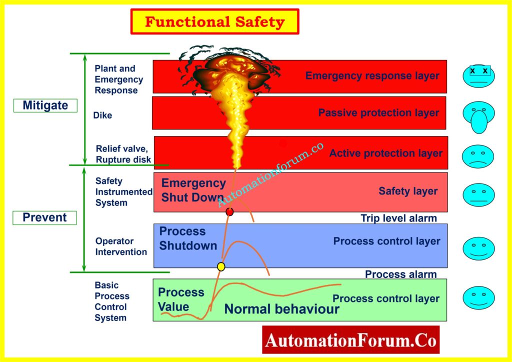
Relationship with Other Layers of Protection
IEC 61511 knows that SIS are just one aspect of a bigger plan for protection. Some other Independent Protection Layers (IPLs) are:
- Mechanical things like relief valves.
- Operator intervention on alarm signals.
- Containment dikes are an example of a passive protection.
LOPA only counts IPLs that meet very high independence standards. This means that the SIS needs to keep working even if the BPCS or other safety measures fail.
Do We Always Need SIS?
Not every risk needs a SIS. As an example:
- If a mechanical relief valve can lower the risk of overpressure to an acceptable level, a SIS may not be necessary.
- If the chance of a danger happening is very low and the effects are small, it would not be right to install a SIS.
The choice is always based on risk, not chance.
Effectiveness of Protection Layers
Each IPL gets a Probability of Failure on Demand (PFD) number. For instance:
- PFD for the relief valve is about 0.01.
- Operator response: PFD = 0.1
- SIL 2 SIF: PFD is about 0.001
The protection layer is more reliable the lower the PFD.
Safety Integrity Levels (SIL)
| SIL | PFD Range | Risk Reduction Factor |
| SIL 1 | 0.1 – 0.01 | 10–100 |
| SIL 2 | 0.01 – 0.001 | 100–1,000 |
| SIL 3 | 0.001 – 0.0001 | 1,000–10,000 |
| SIL 4 | 0.0001 – 0.00001 | 10,000–100,000 |
SIL 4 is not common in process industries; it is mostly used in nuclear and aerospace settings.
Refer the below link for the Top 25 MCQs on Safety Integrity Level (SIL) for Instrumentation and Control Engineers
Safety Lifecycle Requirements
The Safety Lifecycle in IEC 61511 makes sure that the SIS works well from design to retirement.
Phases include:
- Concept – Figure out why SIS is needed and how to safeguard it.
- Hazard & Risk Assessment – Use HAZOP, LOPA to identify hazards.
- Allocation – Give SIS or other IPLs jobs to do.
- Design & Engineering – Choose the architecture, redundancy, and diagnostics.
- Installation & Commissioning – Assemble and test in field conditions.
- Validation – Prove the SIS meets the SRS before startup.
- Operation & Maintenance – Conduct proof testing, repair, and upgrades.
- Modification – Apply MOC for all changes.
- Decommissioning – Safely retire the system.
Safety Requirements Specification (SRS)
Some people would say that the Safety Requirements Specification is the most important deliverable in the IEC 61511 lifecycle. It connects the hazard analysis (HAZOP/LOPA) stage to the engineering design stage. You can’t check if the installed SIS satisfies its expected safety performance without a full and correct SRS.
What to include in SRS documents
The SRS must include:
- Functional description of each SIF: What the function needs to do in certain situations. For instance, “Close both feed valves FV-101 and FV-102 within 3 seconds if the reactor pressure is 12.0 barg or higher.”
- Safety performance standards include Target SIL, the maximum Probability of Failure on Demand (PFD), and the amount of time it takes to respond.
- Limits on temperature, humidity, and vibration are examples of environmental and operational restrictions.
- Diagnostics and fault tolerance mean that the system must be able to check itself and behave in a way that protects it from failure.
- Test intervals: Proof test methods and how often they are done to make sure the SIF stays within its PFD objective.
- Conditions for resetting and restarting the SIS after a trip, making sure it’s done safely.
- Bypass rules: When and how the SIF can be turned off for a short time and what restrictions are in place to stop this from happening.
A recommended practice in the industry is to have a team of people from different fields work together to create the SRS. This team should include process engineers, control engineers, maintenance workers, and safety experts. This makes sure that the specification takes into account both the realities of the process and the limitations of the operation.
Design & Engineering Considerations
When the SRS is done, the design and engineering process starts. The design has to show that the SIS architecture can fulfill or go above the SIL standards.
Design considerations include:
- Hardware fault tolerance is the number of errors the system can handle without losing its safety function (for example, 1oo2 or 2oo3 voting logic).
- Diagnostic coverage is the percentage of dangerous failures that are found automatically.
- Common cause failure mitigation is putting redundant parts in different places and using different technologies to avoid single-point vulnerabilities.
- Response time: Making sure that the logic solver and final pieces can act rapidly enough to reduce the risk.
- Not tied to the BPCS there are separate I/O cards, power supply, and CPUs.
- IEC 61511 uses IEC 61508 as a guide for software development, which means that coding must be structured, testing must be thorough, and version control must be in place.
- Any software used for diagnostics, calibration, or maintenance must be checked to make sure it doesn’t accidentally compromise the safety functions of the SIS.
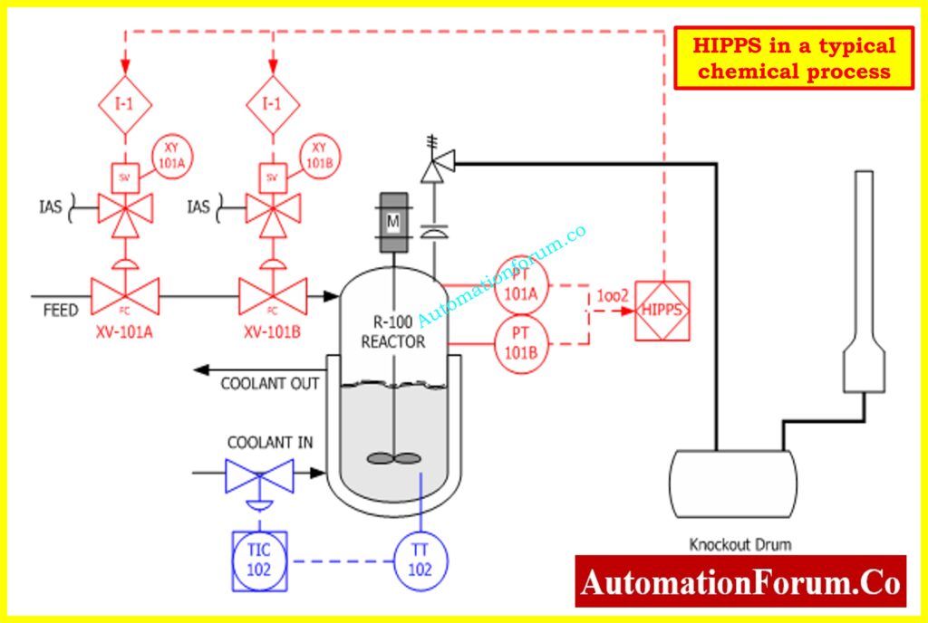
Example:
A high-integrity pressure protection system (HIPPS) might need a 2oo3 sensor setup with extra logic solvers and final parts, each in its own cabinet with its own power supply.
Understand the Process: How does the HIPPS system work in the Oil and gas Industry?
Testing and Validation Requirements
Testing is where the design and the real world come together. Before putting the SIS into service, IEC 61511 says that it must be verified and validated to make sure it operates as planned.
FAT, SAT, loop checks, proof testing
Key testing activities:
- FAT, or Factory Acceptance Test, is done at the vendor’s site before shipping. Simulates process inputs to check the performance of the logic solver, the voting system, and the actions that are taken.
- SAT, or Site Acceptance Test, is done after installation to make that the wiring, field device connections, and system integration are all correct.
- Loop checks are tests that go from the sensor to the logic solver to the last element.
- Safety validation shows that the installed SIS works in the real industrial setting and meets the SRS.
- Proof testing is a set of tests that are done on a regular basis after commissioning to find problems that automatic diagnostics can’t find.
If the proof test only finds 80% of risky failures, the PFD calculation must take into consideration the 20% that it doesn’t find.
Master the Concept: Voting Logic in Safety Instrumented System
Operation, Maintenance and Modification
IEC 61511 says that keeping the SIS in good working order is just as vital as designing it correctly.
Operation:
- Operators need to know how the SIS works, what causes trips, and how to reset it.
- The control room must be able to see the SIS status, such as functions that have been skipped.
Maintenance:
- Mechanical integrity program: regular inspections, calibrations, and tests of how well things work.
- Keeping note of faults and taking corrective action.
- Check if the spare parts are SIS-certified or something similar.
Modification:
- Any changes to SIS hardware, software, or logic must go through a Management of Change (MOC) process.
- We need to look at the hazard analysis again to see if the adjustments have an effect on SIL.
- After changes, testing and validation must be done again.
Example:
If you alter a trip setpoint in the logic solver, even by a small amount, you need to look at it again in terms of safety, revalidate it, and write it down.
Learn More: Understanding 2 out of 2 SOV: Working & Configuration
Decommissioning and End-of-Life
People typically forget about the end-of-life phase of a SIS, however IEC 61511 sees it as an important aspect of the lifecycle.
Decommissioning activities include:
- Before taking something apart, make sure to cut off any dangerous energy sources.
- Keeping system documentation in an archive for future reference and lessons learnt.
- Changing the plant’s hazard analysis to show that the SIS is not there.
Example:
If a process unit is mothballed, the SIS might be turned off. A decommissioning plan makes sure that all leftover energy is eliminated and that jumpers or bypasses don’t make things worse.
Prepare for Interviews: Safety Instrumented System(SIS) Interview Questions and Answers
Compliance Drivers
In many places, following IEC 61511 is not voluntary; it is required by both the law and the industry.
Key compliance drivers:
- OSHA Process Safety Management (PSM) – Recognizes S84 / IEC 61511 as RAGAGEP.
- General Duty Clause – Even if a process is not covered by PSM, OSHA can enforce IEC 61511 compliance if unsafe SIS practices present a hazard to employees.
- EPA Risk Management Program (RMP) – Requires risk reduction measures for processes handling certain chemicals.
- Insurance requirements – Many insurers require proof of compliance before underwriting coverage for high-hazard facilities.
- Corporate governance – Major companies adopt IEC 61511 internally to standardize safety practices across global operations.
Common Errors in IEC 61511 Implementation
Plants often have trouble with SIS deployment, not because of technological issues, but because of gaps in processes and management.
Frequent issues:
- Over-specification of SIL – Designing for SIL 3 when SIL 1 is enough raises costs and makes things more complicated without making them safer.
- Poor independence from BPCS – using the same gear or networks that make SIS less reliable.
- Incomplete proof testing – skipping tests on the latter parts or using the wrong methods lowers SIL over time.
Best Practices
As technology gets better, so are the chances to make SIS work better.
New best practices:
- Digital twins – Digital twins let you test and customize SIS behavior without putting the operation of a real plant at danger.
- Predictive analytics – Predictive analytics lets you use field device diagnostics to guess when something will break before it does.
- Cybersecurity hardening – Set up security zones for SIS networks that meet the IEC 62443 standard.
- Cloud-based documentation – keep SRS and proof test records up to date and available to all stakeholders.
- Integration with Asset Performance Management (APM) – making sure that SIS maintenance fits in with bigger plans for keeping assets healthy.
What IEC 61511 Does and Doesn’t Do
IEC 61511 Does:
- Need a planned safety lifetime.
- Explain how to give SILs to safety tasks.
- Give specific instructions for design, operation, and upkeep.
- Require document for every stage of the lifecycle.
IEC 61511 Doesn’t:
- If you need a SIS hazard and risk analysis, decide that.
- Give specific names of hardware, software, or vendors.
- Take the place of sound engineering judgment.
The S84 / IEC 61511 standard is more than just a set of rules; it is a way of thinking about risk management that is built into engineering and operations. It makes sure that Safety Instrumented Systems are built to do more than simply meet a requirement when they are first turned on; they also need to provide reliable protection for many years.
Following IEC 61511 is both a safety requirement and a competitive benefit, when processes are getting more complicated, operations are becoming more global, and regulations are being stricter. It lets plants show with confidence that they have followed Recognized and Generally Accepted Good Engineering Practice, which protects people, property, and the environment.
FAQ On S84 / IEC 61511 Standard
What is the S84 / IEC 61511 standard?
The S84 / IEC 61511 standard sets lifecycle standards for Safety Instrumented Systems in the process industries to make sure they lower risks as needed.
What is the difference between IEC 61508 and IEC 61511?
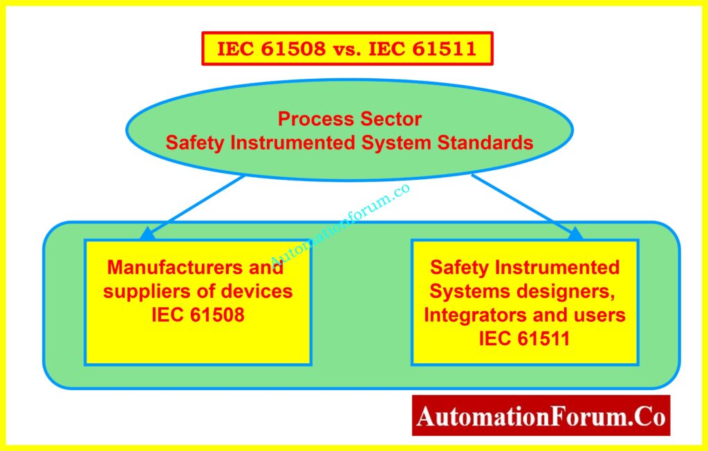
IEC 61508 is a general standard for functional safety, however IEC 61511 is made particularly for the process industry.
What are SIL levels in IEC 61511?
SIL, or Safety Integrity Level, goes from SIL 1 to SIL 4 and sets the goal for how reliable a safety function should be.
Is IEC 61511 compliance mandatory?
IEC 61511 is not usually required by law, but it is considered excellent engineering practice and is often required by regulators, insurers, and business standards.
What is an example of a Safety Instrumented Function (SIF)?
A high-pressure trip in a gas compressor that lets gas out and stops the compressor to stop an explosion.
Take the Quiz: Test Your Expertise in Safety Instrumented Systems (SIS)
Refer the below link to test your expertise in Safety Instrumented Systems (SIS): Knowledge Quiz