Functional safety is more than just a necessity for modern industrial automation; it’s a necessary field of engineering that protects people, the environment, and assets against hazards induced by control system failures.
Automation is always at risk of failing, whether it’s in a chemical factory, an oil refinery, a power station, or a food processing plant. That’s why safety systems need to be carefully planned, follow engineering standards, and have smart diagnostics and backup systems. This is what functional safety is based on.
What is Functional Safety?
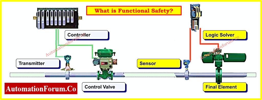
Functional safety is an aspect of a system’s overall safety that depends on the system responding correctly to its inputs. In particular, it makes sure that if a harmful situation comes up, the system will securely control, stop down, or bypass the process to keep people safe.
If a pressure transmitter finds that a vessel is under too much pressure, the safety system must make sure that the right relief valve opens or the compressor stops working to keep the vessel from breaking.
Functional safety systems are designed to:
- Find unsafe situations.
- Do automated things to resolve items.
- Reduce risk to levels that are acceptable.
Key Functional Safety Terms and Concepts
1. Safety Instrumented System (SIS)
When risky process conditions are found, a SIS is a layer of protection that is meant to do certain safety tasks. It has sensors in the field, logic solvers, and final control elements like ESD valves and breakers.
SIS works on its own and is made to be fail-safe, unlike basic process control systems (BPCS).
Quick guide to SIS system basics: What is SIS (Safety Instrumentation System)?
2. Safety Instrumented Function (SIF)
A SIF is a specific task that the SIS does to stop a dangerous occurrence from happening. Each SIF has a certain process condition that it must find.
- A defined process condition it must detect.
- A time constraint within which it must respond.
- A target Safety Integrity Level (SIL).
Example: “If the temperature is higher than 150°C for more than 5 seconds, turn off the heater.”
3. Safety Integrity Level (SIL)
SIL is a way to measure how reliable a safety instrumented function is in numbers. It tells you how much less risk the SIF gives you. Based on an analysis of hazards and risks.
| SIL | PFDavg Range | Risk Reduction Factor (RRF) |
| 1 | ≥10⁻² to <10⁻¹ | 10–100 |
| 2 | ≥10⁻³ to <10⁻² | 100–1,000 |
| 3 | ≥10⁻⁴ to <10⁻³ | 1,000–10,000 |
| 4 | ≥10⁻⁵ to <10⁻⁴ | 10,000–100,000 |
4. PFDavg – Probability of Failure on Demand (Average)
This is the average chance that a system won’t be able to do its safety job when asked to. Lower PFDavg levels mean that something is more reliable.
For example, a PFDavg of 1×10⁻³ suggests that one out of every 1000 requests will fail.
5. Risk Assessment
Finding process hazards and deciding if risk reduction actions are needed. Some of the methods are:
- HAZOP (Hazard and Operability Study)
- What-if Analysis
- Checklist Analysis
- Fault Tree Analysis (FTA)
6. LOPA – Layer of Protection Analysis
LOPA is a semi-quantitative risk assessment method that figures out the necessary SIL of a SIF based on the protective layers that are already in place.
LOPA balances:
- Severity of consequence
- Frequency of initiating event
- Independent Protection Layers (IPLs)
- Target risk tolerance
7. IEC 61508 and IEC 61511
- IEC 61508 is the most important international standard for making sure that electrical and electronic systems work safely.
- IEC 61511: This standard is a particular version of IEC 61508 for process industries like oil and gas, chemicals, and pharmaceuticals.
They outline:
- Safety lifecycle stages
- SIL verification
- System design and validation
- Proof testing requirements
Master SIS interview questions and answers: Safety Instrumented System(SIS) Interview Questions and Answers
8. Safety Lifecycle
The safety lifecycle shows how to make sure something is safe from the time it is planned until it is no longer needed. These are the stages:
- Hazard identification
- Risk analysis
- Safety requirements specification (SRS)
- Design and implementation
- Validation and commissioning
- Operation and maintenance
- Modification and decommissioning
9. Safe Failure Fraction (SFF)
SFF is a number that shows how many of all possible failures of a component are identified or not harmful. It changes the highest SIL that a gadget can be utilized for.
| SFF (%) | Device Type |
| <60% | Not SIL suitable |
| 60–90% | SIL 1–2 |
| 90–99% | SIL 2–3 |
| >99% | SIL 3–4 |
Detecting signals to safely shut down: Signals for Emergency Valve Shutdown in Critical Processes
10. Hardware Fault Tolerance (HFT)
HFT tells you how much more hardware you need to keep working even if something goes wrong without losing safety function. For instance, an HFT of 1 suggests that one part can break without affecting the safety function.
11. Common Cause Failure (CCF)
CCF is when more than one system or component fails at the same time because of the same event, like bad weather or software problems. It makes redundancy less effective, and it can be fixed by:
- Diverse technology
- Physical separation
- Independent power sources
Learn emergency valve function and design: What is an Emergency Block valve and How does it work
12. Diagnostic Coverage (DC)
DC checks how well internal diagnostics can find problems before they cause dangerous situations.
| DC Range | Fault Detection |
| <60% | Low |
| 60–90% | Medium |
| 90–99% | High |
| >99% | Very High |
13. Proof Testing
A test that is done on a set timetable to make sure that a safety function works as it should. It finds failures that haven’t been found yet and helps keep the PFDavg below the required limits.
- Manual or automated
- Required by IEC 61508/61511
- Interval depends on SIL and SFF
Understand voting logic in SIS systems: Voting Logic in Safety Instrumented System
14. Voting Logic (1oo2, 2oo3, etc.)
Redundant sensor logic designs are often used in functional safety systems:
- 1oo1: One sensor, one vote basic.
- 1oo2: One-out-of-two failsafe, allows maintenance.
- 2oo3: Two-out-of-three used in high-integrity systems to avoid nuisance trips.
Voting logic makes things more reliable while keeping them available.
Refer the below link for Designing 2 out of 3 Voting Logic in Control Systems: A Step-by-Step PLC Ladder
15. Fail-Safe Design
Fail-safe systems always end up in a safe condition when something goes wrong. For instance:
- A valve may fail closed on air failure to prevent spills.
- A heater may be shut off when a temperature sensor fails.
This is different from fail-secure, which is used in security systems and makes sure that a system keeps working.
Refer the below link to explore 2oo2 logic with solenoids: Understanding 2 out of 2 SOV: Working & Configuration
16. Safety Field Devices
Devices that meet IEC standards for use in safety systems. Some of these are:
- Pressure/temperature transmitters
- SIL-rated actuators and valves
- Safety contactors and relays
Compare SIS and ESD systems explained: What is SIS? Difference between SIS and ESD
17. Safety PLCs and Logic Solvers
Safety PLCs are programmable logic controllers that have been tested and approved to do SIFs with:
18. Separation and Independence
To avoid common failures, SIS must be both physically and functionally separate from BPCS and other control systems. This includes:
- Separate wiring
- Independent power
- Different network protocols
19. Safety Requirements Specification (SRS)
The SRS lists all of the safety functions, their performance requirements, and design limits. It is the plan for all SIS design and testing work.
What it has:
- Functional description
- SIL target
- Response time
- Proof test interval
- Environment and installation requirements
20. Functional Safety Assessment (FSA)
FSA is an outside check of the safety lifecycle that happens at important times, such after design and before commissioning. It makes sure that the system meets requirements and that it will work safely.
SIS vs PLC vs BPCS overview: Understanding Differences of SIS, PLC, and BPCS in Industrial Automation
21. Automated Proof Testing
In older systems, proof testing is done by hand at set times to make sure that safety instrumented functions (SIFs) are working properly. But as IIoT and smart diagnostics get better, automated proof testing is becoming a very useful way to lower risk and human mistake.
Automated proof tests can be:
- Triggered by system diagnostics
- Scheduled and executed remotely
- Logged digitally for compliance records
These solutions save down on downtime and make guarantee that testing is done the same way every time, especially in high-SIL contexts where test intervals are short.
22. SIL Verification Tools (e.g., exSILentia)
The previous sections talked about SIL calculations in general, but when it comes to actually doing them, people generally use special SIL verification tools like:
- exSILentia by exida
- SILstat by SIS-TECH
- Safety Integrity Level Toolbox (SILT)
These tools are used to:
- Model safety loops (sensor–logic–final element)
- Calculate PFDavg
- Verify whether the SIF meets target SIL
- Generate documentation for audits and FSAs
They make sure that the math and compliance parts of SIL are not left to people who might make mistakes or use spreadsheets that are easy to mess up.
23. Cybersecurity Integration (IEC 62443)
The line between functional safety and cybersecurity has grown quite important as industrial networks become more integrated. Network-based threats could now disrupt safety logic or override diagnostics in safety systems (SIS, BPCS, HMIs).
IEC 62443 is the standard for industrial cybersecurity that goes together with IEC 61511 for process safety. Integration means:
- Network segmentation for safety systems
- Secure communication protocols (e.g., OPC UA with TLS)
- Access control for logic solvers
- Security patches without impacting safety certification
It’s important to think about cyber risks when designing functional safety systems for the future, especially since remote access and cloud diagnostics are becoming more frequent.
24. Dynamic Safety Instrumented Systems (Adaptive Logic)
Traditional SIS logic is static; it always follows the same setpoints and conditions. Adaptive or dynamic logic is the next step in safety logic. With this type of logic, safety reactions alter depending on the condition of the process, the method of production, or outside factors.
Examples:
- Lowering the trip threshold when starting up
- Temporarily turning down some SIFs for maintenance and adding extra safety measures
- Changing the logic for shutting down based on real-time risk profiles
These systems need thorough testing, several layers of safety, and clear records. Dynamic SIS logic is still new, yet it fits with Industry 5.0’s trends toward smart and context-aware automation.
HIPPS explained for oil and gas: How does the HIPPS system work in the Oil and gas Industry?
25. Human Factors in Functional Safety
Even though technology is very advanced, a lot of problems in factories are still caused by people misinterpreting alerts, taking too long to respond, or defects in the design of HMIs. Adding human factors engineering to functional safety makes safety systems easier to use and more effective.
Key considerations include:
- Alarm rationalization (as per ISA-18.2)
- HMI design ergonomics (color coding, prioritization)
- Operator workload analysis
- Training and simulation interfaces
Human aspects are becoming more important in Functional Safety Assessments (FSA). They are necessary to make sure that the safety systems are not only technically sound but also easy for operators to use while they are under stress.
Download: Functional Safety Terminology in Industrial Automation
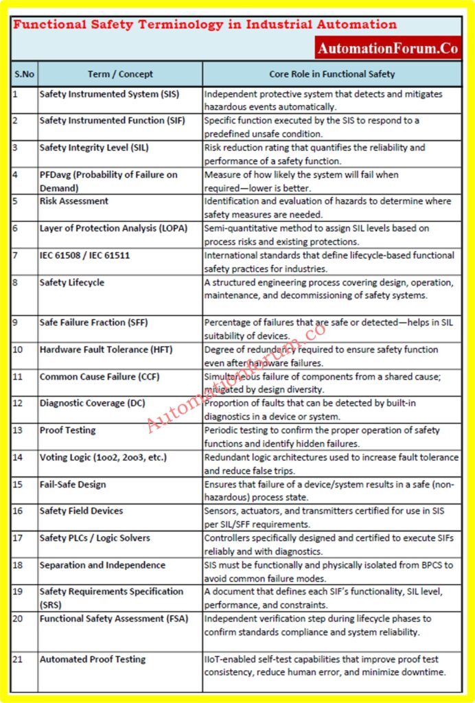
We’ve put together a short Excel checklist with 25 important and new functional safety phrases to help instrumentation and control engineers rapidly find the information they need. This includes important standards like IEC 61508 and SIL levels, as well as contemporary trends like cybersecurity integration, dynamic SIS, and more.
Ideal for EPC engineers, safety professionals, and project documentation.
Functional safety terms aren’t simply jargon; each one is an important part of the safety lifecycle jigsaw. If you know what these phrases mean and how to use them effectively, you can make sure that systems meet international standards, are resistant to failure, protect human life, and keep valuable industrial assets safe.
Every idea is connected to a single goal: to make sure that automated systems work safely and dependably in all situations. This includes risk analysis, diagnostics, SIL assessment, and voting logic.
Functional Safety Terminology – Frequently Asked Questions
What are the key terms used in functional safety?
Safety Instrumented System (SIS), Safety Integrity Level (SIL), IEC 61508, risk assessment, proof testing, and fail-safe operation are some important words in functional safety. There are 25 crucial phrases in our Excel file, along with comments and progress indicators.
Why is functional safety important in industrial automation?
Functional safety lowers the hazards that come with control system failures. It makes ensuring that machines and processes run safely by turning on safety features like shutdowns, alerts, or emergency reactions when problems are found.
What is the difference between SIL and SIS?
SIL (Safety Integrity Level) is a way to measure how well a system works and how reliable it is depending on risk. SIS (Safety Instrumented System) is the system that actually does safety activities. SIL ratings, which range from SIL 1 to SIL 4, show how reliable a system is when it fails.
What standard is followed for functional safety?
What is proof testing in functional safety?
How does cybersecurity relate to functional safety?
Proof testing is a planned test of safety systems to find problems that aren’t obvious. It makes sure that safety systems like ESD (emergency shutdown) loops keep working properly when they break down or when there is a lot of demand.
How often should functional safety systems be proof tested?
According to IEC 61508/61511, the proof test interval depends on the SIL target and failure rate. Most systems are tested every 6 months to 2 years. Regular testing ensures safety functions remain operational.
Test Your Expertise in Safety Instrumented Systems (SIS): Knowledge Quiz
Refer the below link to test your expertise in Safety Instrumented Systems (SIS)