- Why Intrinsic Safety is Important
- Regulatory Framework for Intrinsic Safety
- Top Causes of Intrinsically Safe Loop Failure
- 1. Not Providing a Dedicated Ground Connection
- 2. Not Maintaining Distances Between Intrinsically Safe Circuits
- 3. Failure to Identify Ex Enclosures
- 4. Failure to Identify Intrinsically Safe Cables
- 5. Incorrect Cable Gland Selection or Installation
- 6. Missing Descriptive Documentation
- Functional Safety and IS Loop Reliability
- Practical Checklist to Avoid IS Loop Failures
- Test your Knowledge on Intrinsic Safety Instrumentation Circuits in Oil & Gas Process Industries
- Frequently Asked Questions (FAQ) on Intrinsic Safety
Why Intrinsic Safety is Important
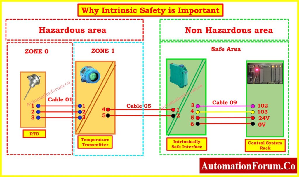
Functional safety is a must in businesses that process things, like oil and gas, petrochemicals, medicines, and mining. In dangerous places, electrical tools and equipment must not create sparks, heat, or energy levels that can ignite flammable gasses or dust. Intrinsic safety (IS) is one of the most widely accepted ways to protect people.
An intrinsically safe loop keeps energy levels below the point where they can start a fire, even when things go wrong. As a result, IS systems are an important part of engineering in dangerous areas. But bad design or implementation can make things less safe, which can cause expensive downtime, breaking the law, and even life-threatening accidents.
The following article goes over the most common reasons why IS loops fail and gives practical tips on how to avoid them. This will help EPC engineers, QA/QC teams, and commissioning specialists set up intrinsically safe systems that are reliable and meet all safety standards.
IS vs Explosion-Proof Explained: Difference Between Intrinsically Safe and Explosion-Proof
Regulatory Framework for Intrinsic Safety
Global Standards Governing IS Systems
Before talking about failures, it’s vital to know what the rules are for intrinsic safety. Every safe IS loop is built on a robust set of rules:
- IECEx Certification Scheme: This scheme gives global recognition to the testing and certification of explosion-proof equipment. It helps manufacturers and end users confidence that the equipment is safe to use in other countries.
- IEC 60079 Series is the main international standard for electrical installations in explosive environments. It covers everything from wiring to safety measures.
- The U.S. National Electrical Code (NFPA 70 or NEC) establishes precise rules on how to install intrinsically safe circuits in Class I, II, and III hazardous areas.
- CSA C22 is a Canadian safety standard that makes sure that electrical installations in dangerous areas satisfy the same strict standards as IEC and NEC.
Refer the below link for the Installation Checklist for Intrinsically Safe Instrument (Apparatus)
Global Standards Governing IS Systems
Intrinsic safety is mostly achieved at the circuit and energy control level by:
- Zener barriers are passive devices that use Zener diodes, resistors, and fuses to limit energy, voltage, and current so that circuits in dangerous areas can’t reach ignition levels, even if there are problems.
- Galvanic isolators use transformers, optical couplers, or capacitive couplers to send signals safely. They not only keep people safe from dangerous places, but they also get rid of ground loops and protect sensitive electronics from voltage spikes.
Top Causes of Intrinsically Safe Loop Failure
1. Not Providing a Dedicated Ground Connection
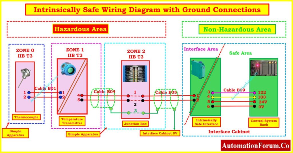
One of the main reasons why IS loops fail is because Zener barriers aren’t grounded properly.
- Zener barriers use a low-resistance grounding method to securely move extra energy away from hazardous places. The barrier’s protective function fails if grounding isn’t reliable.
- Industry guidelines say that the resistance between the barrier’s ground and the farthest reference point should not be more than 1 Ohm. This makes sure that there is always a path for fault current.
- If this isn’t done, a single surge or fault might cause hazardous voltages to build up in the circuit in the hazardous location.
Best Practice:
- Set up a separate grounding conductor just for IS barriers, and don’t use it for structural or lightning protection grounds.
- To avoid ground potential variances, connect the ground conductor at one clear reference point.
- To make sure that resistance levels stay below limits, test and do preventative maintenance on grounding systems on a regular basis.
2. Not Maintaining Distances Between Intrinsically Safe Circuits
It’s important to keep IS circuits separate so that they don’t interact with each other and cause harmful short circuits.
- To make sure that higher-energy circuits don’t mistakenly energize IS loops, IS wire must be kept separate from non-IS cabling.
- Regulatory standards like EN 60079-14 say that IS terminals and conductors must be at least 50 mm apart from circuits that are not IS.
- If there is no isolation, short circuits or wiring problems could get around safety parts, making a dangerous source of ignition.
Best Practice:
- Follow the IEC/EN standards for the required creepage and clearance distances.
- To stop unintentional crossing, use physical barriers or dividers inside panels and junction boxes.
- Train technicians who install things how to spot and obey IS segregation rules.
3. Failure to Identify Ex Enclosures
Another common reason for IS loop difficulties is not properly identifying or not identifying Ex enclosures at all.
- To avoid mistakes while using or maintaining ex enclosures that hold inherently safe circuits, they must be properly and permanently identified.
- Using light blue labels or nameplates to tell IS enclosures apart from non-IS ones is standard practice in the industry.
- Marking is not optional according to EN 60079-14; it is a necessary aspect of an intrinsically safe installation.
Best Practice:
- Put blue caution labels on all IS enclosures, junction boxes, and terminal housings.
- Use engraved or permanent labels instead of stickers that might come off or fade over time.
- Put enclosure numbers, loop IDs, and safety recommendations right on the enclosure to make it easier to fix and keep up with.
NAMUR Sensors: Safety Edge:Why NAMUR Sensors are Essential in Explosive and Hazardous Areas ?
4. Failure to Identify Intrinsically Safe Cables
People often forget to identify cables, yet it’s an important part of keeping the system safe.
- Light blue sheathing or insulation is only used for IS cables, according to custom. This visual indication stops people from getting confused when they are installing or fixing something.
- Using bright blue wires for things other than IS is against EN 60079-14 rules and makes things dangerous.
- Cable insulation can also get worse if the cables are routed incorrectly, if they bend too sharply, or if they are stressed at the glands.
Refer the below link for the Intrinsically Safe Cables for ATEX Zones – Complete Checklist for EPC Engineers
Best Practice:
- To keep global awareness and compliance with the rules, only use light blue wires for IS circuits.
- Place junction boxes so that cables can leave with a bend radius that is big enough to prevent putting stress on glands and terminations.
- Use protective conduit or cable tray routing in places where cables could be damaged by physical or environmental stress.
Pick the Right Cable Gland: Cable Gland Selection for Hazardous Area Installations
5. Incorrect Cable Gland Selection or Installation
Even if you choose the right cable, choosing the wrong cable gland can still cause IS loop failures.
- You need to use the right type and size of cable for the cable glands to work. If you don’t, the seal won’t work.
- If the gland isn’t rated for explosions, outside strain or twisting can go straight to the conductors, which can cause problems.
- Always seal unused entries; otherwise, the integrity of the explosion protection will be undermined.
Best Practice:
- Choose certified cable glands that are rated for IS circuits and can handle the circumstances in the environment (dust, moisture, chemicals).
- To make sure the cable is compressed correctly without breaking, follow the manufacturer’s torque guidelines during installation.
- Use blind plugs or line bushings that are safe for hazardous regions to seal off any entry that aren’t being used.
- Include regular checks of glands during shutdowns or maintenance that is done to prevent problems.
IS or Non-IS Cables?Difference Between Intrinsically Safe (IS) and Non-IS Cables
6. Missing Descriptive Documentation
Incomplete or absent documentation is a surprisingly prevalent point of failure.
- IS loops need very detailed records that show how each part, cable, and enclosure is connected to its certification.
- When auditing or fixing problems, it is almost impossible to check system safety without loop drawings and compliance data.
- IEC 61508 and IEC 61511 also require that there be documentation for functional safety compliance.
Best Practice:
- Keep all of your documents, such as loop diagrams, datasheets, certificates of conformity, and calculation reports, in one place.
- Make sure that all of the installed equipment is exactly what the design says it should be.
- As soon as you change, add to, or replace something, update the documentation.
- Store records in a centralized, easily accessible system for use by EPC, QA/QC, and commissioning engineers.
Refer the below link for the 82 Essential Drawings and Documents for Instrumentation and Control Engineers
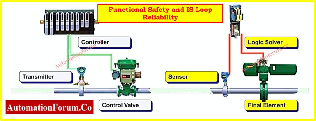
Functional Safety and IS Loop Reliability
Key Considerations for Engineers
Intrinsic safety is more than just following installation regulations; it is a key aspect of the functional safety lifecycle.
- SIL (Safety Integrity Level): Safety instrumented systems have a lot of IS loops. Any damage to the loop’s integrity could lower the SIL rating and make it harder to manage risk at the facility.
- Testing for proof: Testing IS barriers, isolators, and cabling on a regular basis makes ensuring they still work as they should.
- Diagnostics and Redundancy: Advanced galvanic isolators with built-in diagnostics and extra IS channels make loops more reliable and shut down on false trips.
Plants can get the most reliability, compliance, and safety assurance by including IS design and maintenance in their functional safety strategy.
Why IS Systems Really Matter: What is intrinsically safe system and what is its importance?
Practical Checklist to Avoid IS Loop Failures
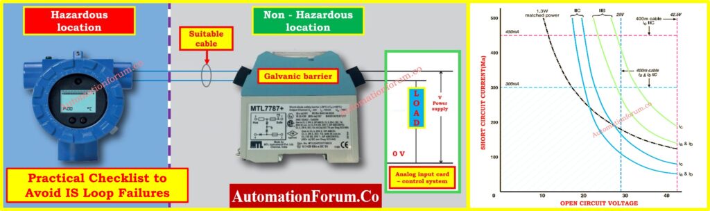
To make sure that intrinsically safe loops are built, installed, and kept up, a thorough verification approach is needed. The following checklist goes into further detail about the six stages that every engineer should take.
| Step | What to Verify | Detailed Explanation | Standard / Best Practice |
| 1 | Ensure Zener barrier ground resistance is less than 1 Ohm | There must be a separate ground for each Zener barrier that has a resistance of less than 1 Ohm. This makes sure that if there is a problem, too much current is securely sent to the ground without creating dangerous voltages in the dangerous area. Grounding should not depend on structural steel or lightning systems. To find rust, loose lugs, or broken ground conductors, it is important to check them regularly. | IEC 60079 / EN 60079 |
| 2 | Keep IS and non-IS circuits at least 50 mm apart from each other. | Wiring, terminals, and devices that are intrinsically safe must be at least 50 mm away from non-IS circuits or separated by barriers. This stops electrical problems or wiring mistakes from sending dangerous energy into IS loops. Long-term dependability and compliance depend on proper separation in junction boxes, panels, and cable trays. | EN 60079-14 |
| 3 | Label all Ex enclosures with light blue identification | Permanent light blue labels, plates, or tags must be used to clearly indicate all enclosures that hold IS circuits. This stops people from accidentally changing things, mixing things up, or doing risky maintenance. Using engraved or long-lasting labels that can handle tough industrial settings is standard practice. For simple recognition, blue color coding must be the same across the building. | IEC/EN labeling rules |
| 4 | Use only light blue-sheathed cables for IS circuits | Light blue sheathing or insulation must be used to wire intrinsically safe circuits so that they can be easily seen. To avoid confusion, these wires should not be used for anything other than IS. To prevent wires from mechanical stress and gland damage, junction boxes should be placed so that the bend radius is correct. In places where the weather is bad, it’s best to use protective conduit or tray routing. | EN 60079-14 |
| 5 | Select and install certified cable glands, seal unused entries | Cable glands must be able to handle explosions, fit the cable’s diameter, and be put in according to the manufacturer’s torque specifications. This makes sure that the seal is still good and that there is less mechanical stress. All empty enclosure entries must be sealed with certified blind plugs or bushings. Regular checks should make sure that the glands are still intact, tight, and undamaged. | IEC 60079 / Manufacturer guidelines |
| 6 | Keep full descriptive documentation for all IS loops | All documentation must be complete, including loop diagrams, certificates of conformity, datasheets, and calculation reports. This makes guarantee that each installed IS loop is the same as the approved design and can be checked during audits or maintenance. After changes are made, records should be updated and kept in a central system that EPC, QA/QC, and commissioning teams can all access. | IECEx / IEC 61508 / IEC 61511 |
A system that is essentially secure is only as powerful as its weakest part. A little mistake, such not separating circuits, not keeping records, or using the wrong cable gland, might make the loop less safe.
Engineers can: By knowing and staying away from these six main reasons why IS loops fail,
- Make sure that functional safety is followed more closely
- Lower the chance of expensive breakdowns and downtime
- Protect people, property, and procedures in dangerous fields
Intrinsic safety isn’t only about the tools; it’s also about following rules, doing things the right way, and being disciplined in your engineering. A proactive strategy makes sure that IS loops stay safe, dependable, and compliant during their whole life.
Test your Knowledge on Intrinsic Safety Instrumentation Circuits in Oil & Gas Process Industries
Refer the below link to test your Knowledge with out TAdvanced Quiz on Intrinsic Safety Instrumentation Circuits in Oil & Gas Process Industries
Frequently Asked Questions (FAQ) on Intrinsic Safety
What happens if intrinsically safe barriers fail?
If an intrinsically safe barrier breaks, it can let too much energy, voltage, or current into the circuit in the dangerous area. This goes against the idea of inherent safety and could make combustible gasses or particles catch fire. To stop this from happening, barriers are made using extra parts (such fuses, resistors, and Zener diodes) and need to be tested, checked, and grounded on a regular basis.
What is the concept of intrinsically safe?
The idea behind intrinsic safety is to make electrical equipment and circuits so that they can’t release enough electrical or thermal energy to start an explosion, even when anything goes wrong. Barriers, isolators, and certified IS parts are used to limit voltage, current, and energy in this way.
What is another word for intrinsically safe?
IS is a common short form for “intrinsically safe.” Ex i (used in IEC standards) and explosion-proof via energy limitation are two other terms that are similar. But “intrinsically safe” is the phrase that most people in hazardous area engineering know.
Choose IS for Safer Plants: Why Choose Intrinsic Safety (IS) for Hazardous Area Instrumentation?
What is an IS loop?
An IS loop is a whole electrical circuit in a dangerous region that has been made to meet intrinsic safety standards. It usually has a field device (such a sensor or transmitter), an inherently safe barrier or galvanic isolator, and the input and output for the control system. The loop makes sure that any fault energy stays below the amount that would start a fire.
What is the limit of intrinsically safe power?
In an intrinsically safe circuit, the maximum power is limited so that ignition can’t happen, even if there is a problem. In most cases, IS circuits can only handle 30 V and 100 mA, and they usually only use 1.3 W of power. The exact restrictions depend on the gas group, zone classification, and IEC 60079 criteria for equipment certification.
 loop failure and how to avoid them with best practices, standards, and compliance tips.)