- What Is a Cable Gland?
- Why Cable Gland Selection Is Critical in Hazardous Areas
- Cable Gland Selection Criteria
- Explosion Protection Types and Gland Compatibility
- When to Use Barrier Glands (Ex d, Ex e, Ex nR)
- Environmental Considerations
- EMC Protection and Shielded Cables
- Certification and Documentation
- Hybrid Zones / Mixed Gas and Dust Environments
- Installation & Inspection Considerations
- Long-Term Maintenance and Lifecycle Management of Cable Glands
- Cable Gland Selection Checklist for Hazardous Area Installations (Excel Download
Cable glands are very important for keeping electrical systems safe and preventing explosions in places where there are flammable gasses, vapors, or dust. For safety and dependability, it is important to choose the right parts and install them according to IEC 60079 standards.
This full guide explains how to choose the right type of cable gland depending on the type of cable, the classification of the hazardous area, the method of protection (Ex d, Ex e, Ex nR), the environment, and the criteria that need to be checked.
This 2025 guide also includes the latest best practices, IEC 60079-0/-1/-14/-31, ATEX, and IECEx recommendations. This helps EPC engineers, project designers, and inspectors make choices that are both technically sound and in compliance with the rules.
What Is a Cable Gland?
A cable gland is a mechanical device that:
- Keeps gas, dust, and moisture from getting into the cable entry
- Gives mechanical strain a reduction
- Makes sure that grounding and earthing stay connected (for armored cables)
- Keeps the enclosure’s ingress protection (IP) and explosive protection in place.
The cable gland must keep combustible materials from getting in through the cable entrance point in places that are dangerous, like refineries, petrochemical factories, offshore rigs, and grain silos.
Top Cable Tray Accessories to Solve Common Cable Management Problems: How to Fix Common Cable Management Issues using Cable Tray Accessories
Why Cable Gland Selection Is Critical in Hazardous Areas
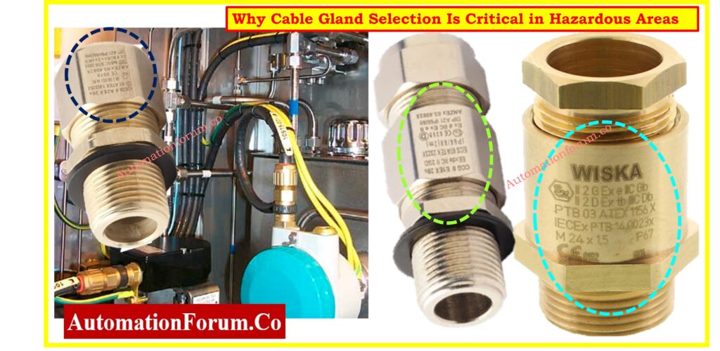
In hazardous locations (Zones 0, 1, and 2 for gas and Zones 20, 21, and 22 for dust), choosing the wrong gland may let in explosive gasses or dust, which raises the risk of ignition inside the enclosure.
- Loss of explosion protection integrity, which could make approved equipment standards no longer valid.
- Ignition because of a frayed cable, especially when there is too much load or a problem in the field.
- Not following IEC 60079-14, which could lead to legal and operational problems.
- Explosion containment is less effective (particularly in Ex d enclosures)
- Allow gas move into flameproof housings
- Make ignite sources by connecting things loosely.
- Lead to not following IEC 60079-14:2022, which has an effect on insurance and legal liabilities
Cable Gland Selection Criteria
Choosing the right cable gland depends on a number of technical and environmental factors:
Cable Type and Construction
The type of gland and sealing method depend on the cable’s interior structure, such as whether it is armored or unarmored, has bedding, or fillers. When choosing, you can use cable designations like WA, SWA, AWA, ZYA, and XYZ.
| Cable Type | Description |
| W | Single Wire Armour (SWA), commonly used in underground or heavy-duty applications |
| AWA | Aluminium Wire Armour, suitable for single-core cables in magnetic environments |
| Z | Double Steel Tape Armour, offers moderate protection in dry and light-duty applications |
| Y | Aluminium Strip Armour, lighter than steel and ideal for non-magnetic areas |
| T | Pliable Wire Armour, used for flexible conduits or mobile industrial connections |
| X | Braid, mainly used in instrumentation or small-diameter flexible cable applications |
| Unarmoured | No armour; requires proper sealing for Ex applications to maintain IP and safety |
Gland Types and Functions (A/B/C/D/E, E1/E2)
Glands are put into groups according on the sealing zones they work on:
| Gland Type | Function |
| A | Single seal only; for simple unarmoured cable installations needing IP protection |
| B | Armour clamp only; provides mechanical retention without sealing on cable sheath |
| C | Clamp + outer seal; used when only the outer sheath needs sealing for ingress |
| D | Clamp + inner seal; preferred for cables without adequate outer sheath sealing |
| E | Clamp + inner and outer seal; ensures maximum integrity for hazardous environments |
Variants such as E1, E2 include enhanced sealing and bonding:
- E1 and E2 are examples of variants that have better sealing and bonding:
- E1: IP66 sealing on the inner and exterior sheaths for extra protection against water getting in
- E2: The same as E1, but with an electrical bond for metallic inner sheath cables (like lead).
Gland Sizing and Fitment Best Practices
As per IEC 60079-14 Clause 10.2, cable glands must fit the actual cable diameter perfectly.
- Don’t use sealing tape, heat shrink, or anything else that isn’t yours to make things fit better.
- Glands that are too big or too little can make sealing less effective, which can let gas in and cause failure.
- You can’t use tape, fillers, or heat shrink sleeves to change the fit.
- Before installing, check the manufacturer’s sizing charts and use a micrometer to double-check.
Instrument Cable Schedule Format and Best Practices: Instrument Cable schedule
Explosion Protection Types and Gland Compatibility
The way your cable gland protects itself must be the same as or better than the way the device it connects to protects itself.
| Equipment Protection | Acceptable Gland Protection |
| Ex d | Ex d only; ensures flameproof sealing under explosive conditions |
| Ex e | Ex d or Ex e; increased safety, but no flame propagation allowed |
| Ex nR | Ex d, Ex e, Ex nR; restricted breathing for Zone 2 applications |
| Ex i | Ex d, Ex e, Ex nR; suitable for intrinsically safe circuit entries |
| Ex p | Ex d, Ex e, Ex nR; pressurization protects internal components from gas ingress |
Never use Ex e glands on Ex d equipment unless certified for Ex d.
Refer the below link for the Complete Cable Glanding & Termination Checklist for Hazardous Areas: Checklist for Cable Glanding & Termination
When to Use Barrier Glands (Ex d, Ex e, Ex nR)
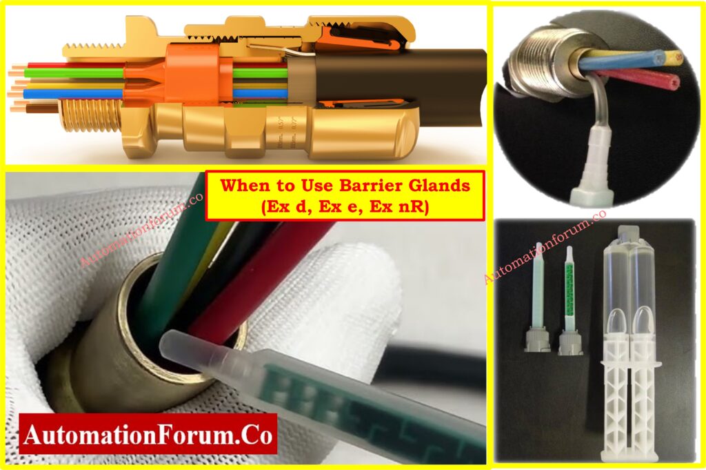
Barrier Gland in Ex d Environment- Mandatory Cases
To seal each conductor separately, barrier glands need to use compound or resin.
Use barrier glands when:
- when the cable isn’t spherical, which makes it more likely that the compound won’t seal well and gas will flow through.
- There is no extruded bedding, which lets gas move into the equipment enclosure.
- Fillers are hygroscopic, which means they soak up water and can move explosive gasses.
- The inner sheath is missing, therefore the insulation around the conductor is open and unsealed.
IEC 60079-14: When Barrier Glands are Not Required
IEC 60079-14 gives a clear way to use barrier glands in Ex d:
Barrier Gland Required Unless:
- Gland is certified to meet the most recent IEC requirements for Ex d.
- The cable is round and small, and the bedding is smooth and extruded.
- Cable is at least 3 meters long, which makes it less likely that gas will go down it.
- Gland has passed Ex d type testing with the cable it was meant to work with.
Barrier Gland in Ex e / Ex nR
Use barrier glands also in:
- Barrier glands should also be used in Ex e situations where there is a chance that gas could move through cable strands or gaps in insulation.
- Ex nR applications when cable seals don’t keep gas in or aren’t certified for limited breathing.
Tip: Always opt for a barrier gland when there is doubt. It’s safer and compliant.
Environmental Considerations
Temperature Rating
The equipment nameplate says what the ambient temperature range is, and cable glands must work reliably within that range.
- Cable glands don’t get a precise “T” rating as motors or enclosures do.
- But they must be able to handle temperatures that are equal to or higher than what the equipment needs.
- Check that the sealing gaskets and glands are tested as a whole unit under high temperatures.
- The sealing compound and gland material (brass, stainless) must be qualified for heat.
- IEC 60079-0 says that the assembly must be tested, which includes the cable, gland, and enclosure.
Ingress Protection (IP Rating)
For IP66/IP68, ensure:
- Use approved sealing washers with matching glands to keep IP66/IP68.
- Clause 10.2 of IEC 60079-14 says that thread washers must be part of the tested assembly.
- Do not use generic washers; only use the ones that come with the certification.
- Getting the right amount of torque on gland threads and washers
- Field check for continuity and gasket compression
Dissimilar Metals and Bi-Metallic Corrosion
- When the metal of the gland and the metal of the enclosure come into contact with each other, they can produce a lot of corrosion.
- When you can, use materials that match, such a brass gland with a brass enclosure.
- Nickel-plated brass is the best at resisting corrosion and is commonly used in industry.
- Don’t mix brass glands with aluminum enclosures.
- Use brass with nickel plating or 316L stainless steel.
- Make sure the nickel plating is at least 10 μm thick (IEC 60079-1 allows 8 μm but higher is better).
Refer the below link for the Cable Tray Fill Percentage Calculator – Accurate Sizing for Project Engineers
Corrosive Environments
Corrosive agents like:
- Salt spray on offshore platforms or in marine areas is an example of a corrosive agent.
- Ammonia or SO₂ in factories that make chemicals or fertilizers
- High humidity environments speed up the breakdown of metals.
Recommended materials:
- Brass glands with nickel coating that is at least 10 microns thick
- 316L stainless steel for the best resistance
- Coated glands that are suited for tough industrial settings
In these situations, use glands made of stainless steel or PTFE.
Please keep in mind that IEC 60079-1:2014 says that plating should be at least 8 µm, while the recommended practice is 10–12 µm.
EMC Protection and Shielded Cables
EMC gland types work with instrumentation or VFD cable that has foil or braided shields:
- Provides 360° grounding of the shield
- Gives the shield a full 360° grounding
- Needed for Ex i or functional safety uses with narrow signal margins
- Must not lower the IP rating or Ex classification
Cable Tray Size Calculation Made Easy – Guide for EPC Project Engineers: Cable Tray Size Calculation for Project Engineers
Certification and Documentation
Required Documentation
- IECEx/ATEX certificate from the gland maker
- Installation guide and drawing IP test findings (IP66/IP68)
- Certificate of material traceability (MTC)
Tagging and Markings
Per IEC 60079-0, glands must be marked with:
- Ex marking (e.g., Ex d IIC Gb)
- IP rating
- Operating temperature range
- Certification number and manufacturer name
Hybrid Zones / Mixed Gas and Dust Environments
In a lot of factories, especially chemical plants, offshore platforms, and food processing plants, the equipment is sometimes put in places where there are both flammable gasses and dust that can catch fire. These areas are called hybrid zones, and you need to pay extra attention to them while choosing a cable gland.
What is a Hybrid Zone?
A hybrid zone is a place where gas and dust dangers are present at the same time or in distinct operational situations. For instance, a motor might work in a place where combustible fumes are present all the time, yet dust might build up when the engine is turned off or cleaned.
This means that any cable gland that goes in this region has to be certified to guard against both gas (like Ex d or Ex e) and dust (like Ex t).
Cable Gland Requirements for Hybrid Zones
Always utilize cable glands that are rated for both gas and dust conditions. There will be indications on these, such as Ex d IIC Gb or Ex t IIIC Db.
To keep gas and dust from getting into the enclosure, the gland must have a high ingress protection level, usually IP66 or IP68.
If you’re not sure if the region is gas, dust, or a mix of the two, the best thing to do is to pick a gland that can handle both. This keeps the installation safe for a long time and avoids problems with compliance.
Instrumentation Cable and Wiring Inspection – EPC Engineer’s Essential Procedure: Instrumentation Cable and Wiring Inspection Procedure: Essential checklist for Project Engineers
Installation & Inspection Considerations
Best Practices for Installation
- To avoid mistakes when putting things together in the field, pick cable glands with pieces that are easy to see.
- Don’t buy glands that have small or loose pieces that could be lost during installation.
- Choose barrier glands with a liquid resin component since they are safer and easier to install.
- To make sure the IP seal is tight, make sure the washer is in the right spot and is appropriately compressed.
Inspection-Friendly Features
To facilitate easier maintenance and audits:
- Choose glands that have clear inspection windows or compression rings that are easy to see.
- Use glands that can’t be turned around, so that the assembly can’t be put together the wrong way.
- Make sure that all accessories, such as washers and gaskets, are listed in the certification papers.
- Put glands in places where you can easily get to them to tighten them again for future inspections.
Long-Term Maintenance and Lifecycle Management of Cable Glands
Cable glands are typically thought of as passive parts, but their performance gets worse over time because of exposure to the environment, mechanical stress, and temperature cycling, especially in tough industrial areas. IEC 60079-17, which sets rules for inspecting and maintaining electrical equipment in dangerous situations, is always followed when there is good long-term planning.
Periodic Inspection Recommendations
- You should check the torque every year in places where there is a lot of vibration, including offshore platforms, rotating machinery, or big compressors.
- As part of the preventive maintenance plan, you should visually check for rust, seal wear, or gland loosening.
- More frequent inspections are recommended in Zone 1/21 and Zone 0, depending on the risk assessment of the location.
Spare Parts and Retrofit Planning
- When you replace equipment, be sure that the new cable’s OD and construction still match the gland that was initially placed.
- If changes are made, check the assembly’s Ex certification again, including the type of gland, the enclosure, and the IP rating.
Record-Keeping and Documentation
Keep a record of inspections for each gland, including the date of installation, the amount of torque used, and any problems that came up.
Keep all Ex certifications and installation drawings with revision tracking to help with audits and following the rules.
By using these lifecycle tactics, EPC engineers and site maintainers may make equipment last longer, do less rework, and stay in complete compliance with worldwide explosion protection regulations.
Instrumentation Cable Tray Installation & Inspection Checklist [IEC 60079 Compliant]: Instrumentation Cable Tray Installation Checklist and Inspection Procedure
Cable Gland Selection Checklist for Hazardous Area Installations (Excel Download
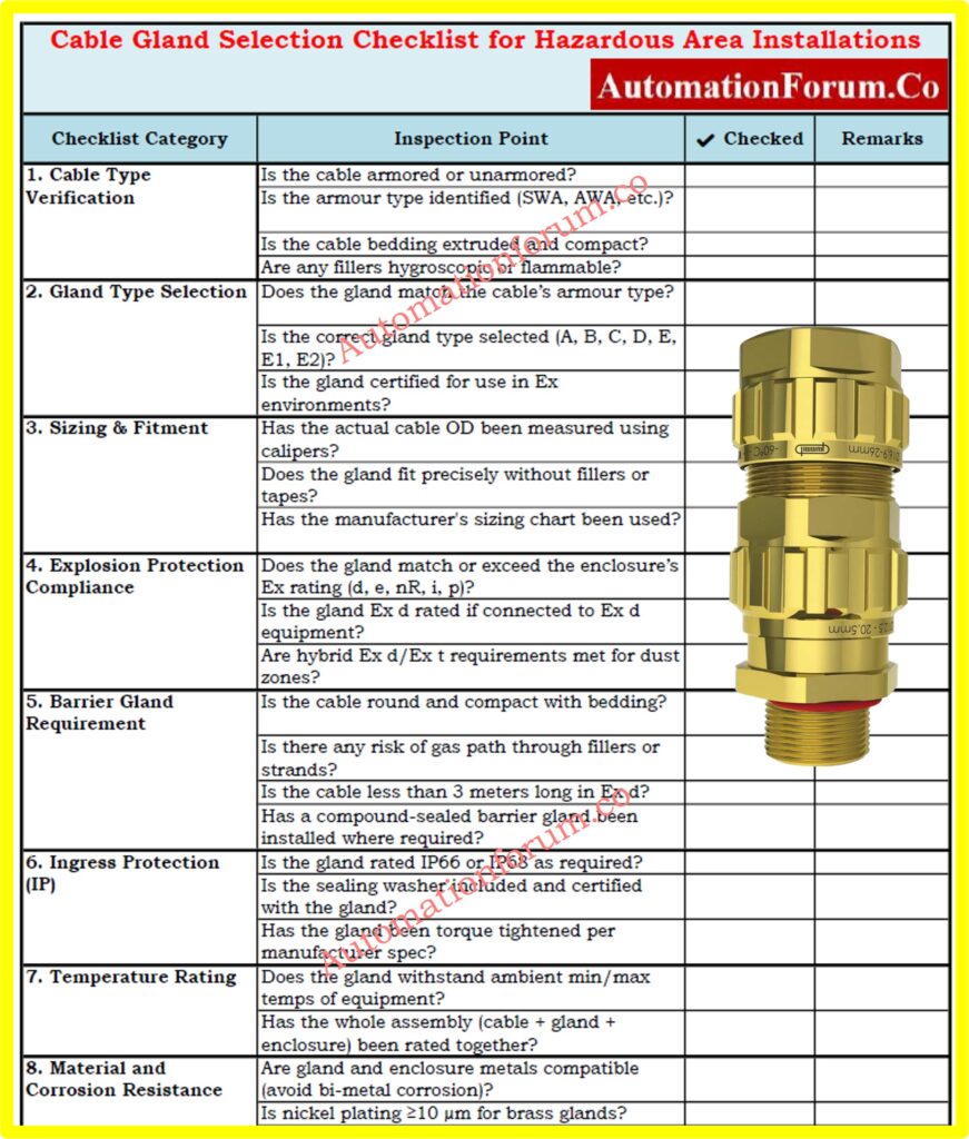
This Excel checklist will help you make sure that you choose the right cable glands, install them correctly, and follow all the rules in hazardous areas (Zone 0/1/2 and Zone 20/21/22). This checklist is based on IEC 60079-0/-1/-14/-31 and includes things like the kind of cable, the size of the gland, the method of Ex protection, the use of barrier glands, corrosion resistance, compatibility with hybrid zones, and procedures that make the equipment suitable for inspection. This is great for EPC engineers, inspectors, and project designers that are working on installations that are shielded from explosions.
Review certification data (ATEX, IECEx) for gland, accessories, and cable assemblies.
If unsure about the cable structure or installation environment, choose a barrier gland.
Design for long-term maintainability, using glands that support inspection and retightening.