- What is Foundation Fieldbus?
- Core Characteristics of Foundation Fieldbus
- Types of Foundation Fieldbus
- Significance of Foundation Fieldbus in Industrial Automation
- What is the Architecture of the Foundation Fieldbus?
- Advantages of Foundation Fieldbus over Conventional Analog and Discrete Field Instruments:
- Comparison Between Conventional Wiring and Foundation Fieldbus Network
- Conventional Wiring vs Foundation Fieldbus Network
- Various Terminologies used in Foundation Fieldbus Network System
- What is the Standard for Foundation Fieldbus?
- What are the Typical Components of a Fieldbus Segment?
- What is the Speed of Foundation Fieldbus?
What is Foundation Fieldbus?
- FOUNDATION Fieldbus (FF) has emerged as a crucial standard for digital field instrumentation in industrial automation.
- Unlike typical communication buses, FF not only allows for digital communication between instruments, but it also enables them to execute complicated control algorithms directly.
- This introduces the idea of a distributed control system (DCS) to the field units themselves, starting the next phase of control and measurement systems.
- Despite its modest adoption rate, particularly in retrofit projects, it is increasingly popular in construction projects.
- For greenfield installations, FF is the preferred technology due to its lower installation times.
Core Characteristics of Foundation Fieldbus
What are the Characteristics of Foundation Fieldbus?
- Foundation Fieldbus is an all-digital, serial, two-way communication technology that serves as the basic network for plant and factory automation.
- It is managed by FieldComm Group and operates on an open architecture, establishing itself as a dynamic solution for simple and advanced regulatory control applications. While FF is largely used in process sectors, it has recently found applications in power plants.
- FF’s open architecture assures compatibility and versatility, allowing for simple interaction with a variety of control functions.
- This versatility makes it an excellent choice for both basic regulatory control and discrete control applications.
Types of Foundation Fieldbus
What are the different types of Foundation Fieldbus?
- Foundation Fieldbus (FF) is a digital communication protocol widely utilized in process control and automation systems.
- It facilitates seamless communication among various field devices, including sensors, actuators, and controllers, contributing to the efficiency and intelligence of industrial processes.
- There are distinct types of Foundation Fieldbus, each tailored to meet specific requirements:
Foundation Fieldbus H1: Bridging Field Devices and Host Systems
- Operating at 31.25 kbit/s, connects field devices to host systems.
- Delivers both communication and power over standard twisted-pair wiring.
- Versatile for use in conventional and intrinsic safety scenarios.
- Most commonly adopted FF implementation.
- Ensures reliable interaction between components in the automation network.
HSE (High-speed Ethernet): Accelerating Connectivity
- Operates at higher speeds (100/1000 Mbit/s).
- Links input/output subsystems, host systems, linking devices, and gateways.
- Introduces high-speed data exchange within the automation ecosystem.
- Currently does not provide power over the cable.
- Ongoing efforts to leverage IEEE802.3af Power over Ethernet (PoE) standard.
Wireless FF: Extending Possibilities
- Utilizes wireless protocols for communication.
- Eliminates the need for extensive cabling.
- Provides flexibility in deployment.
- Particularly valuable in hard-to-reach areas.
- Overcomes physical constraints where wired connectivity is impractical.
Combination of Foundation Fieldbus H1, HSE, and Wireless FF
- The combination of Foundation Fieldbus H1, HSE, and Wireless FF offers a comprehensive framework to meet diverse industrial communication needs.
- H1 ensures reliability and power efficiency, HSE accelerates high-speed data exchange, and Wireless FF adds flexibility in challenging environments.
- Together, these implementations contribute to the evolution of industrial communication, aligning with the dynamic requirements of modern automation systems.
Significance of Foundation Fieldbus in Industrial Automation
What is the Significance of Foundation Fieldbus in Industrial automation?
Reduced Cabling and Installation Costs
- Single segment replaces numerous point-to-point wires.
- Streamlines wiring infrastructure, reducing complexity.
- Minimizes installation time and labor costs.
Improved Data Acquisition and Control
- Real-time data exchange facilitates better process optimization.
- Enables faster response to changes in the production environment.
- Enhances overall system efficiency and control.
Enhanced Asset Management
- Advanced diagnostics provide insights into the health of field devices.
- Predictive maintenance capabilities help prevent unexpected failures.
- Optimizes asset performance, extending equipment lifespan.
Increased Safety and Reliability
- Robust communication ensures reliable data transfer.
- Intrinsic safety features enhance the overall safety of the system.
- Reduces the risk of equipment failures and operational disruptions.
What is the Architecture of the Foundation Fieldbus?
Open Architecture
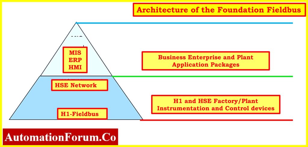
- Promotes interoperability between devices from different manufacturers.
- Allows for the integration of diverse components within the automation ecosystem.
- Facilitates a more flexible and adaptable automation infrastructure.
- By way of the Data Servers, Management Information Systems (MIS), Enterprise Resource Planning (ERP), and Human Machine Interface (HMI) are able to have access to the information contained inside the H1 Fieldbus.
- The Fieldbus extends the operators’ vision to include the entire process.
Advantages of Foundation Fieldbus over Conventional Analog and Discrete Field Instruments:
Multidrop Wiring
- Foundation Fieldbus supports up to 32 devices on a single pair of wires (segment), potentially more with repeaters.
- Practical considerations often lead to 4 to 16 devices per H1 segment, offering significant wiring and installation savings.
- With 1000 devices, traditional technology would require 1000 wire pairs, while Foundation Fieldbus needs only 60 to 250 wire pairs.
Multivariable Instruments
- A single wire pair in Foundation Fieldbus can handle multiple variables from one field device.
- Fieldbus facilitates the integration of “multiple variables” from individual devices into the control system for various purposes such as trend analysis, asset management, predictive maintenance, reporting, archiving, and process optimization.
- MVT Devices: DP Transmitter, Magnetic Flowmeter, Vortex Flowmeter, Ph Transmitter, Coriolis Flowmeter, Valve Positioner
- For example, one temperature transmitter can communicate inputs from multiple sensors, reducing both wiring and instrument costs.
Two-way Communication
- Foundation Fieldbus enables two-way communication, allowing devices to accept control outputs and send back real-time feedback.
- Traditional analog systems would require additional wire pairs for such communication.
New Type of Information
- Foundation Fieldbus devices provide information about their operating status and the validity of the data they transmit.
- Eliminates the need for extensive device verification checks, improving efficiency and detecting potential issues before they become major problems.
Predictive Diagnostics
- Predictive diagnostics in Foundation Fieldbus devices help increase plant uptime and performance.
- Detects or predicts deteriorating performance and failure conditions before they cause operational problems.
- Fieldbus devices’ self-diagnostic and communication features boost asset utilization, which lowers downtime.
- When maintenance and plant employees are notified corrective action can be done quickly.
- Process control is no longer the only aspect of process management. Asset management is now included, utilizing a multitude of data from your assets.
Control in the Field
- Foundation Fieldbus offers the option of executing control algorithms in field devices rather than a central host system.
- Enhances performance and reduces costs, enabling automatic control to continue in case of host-related issues.
Control Strategy
- Utilizing Standard Function Blocks, the Control Strategy is implemented into practice.
- These standard function blocks allow the field device to perform many control system operations, including AI, PID, and AO.
- Control can be distributed among field devices, which can minimize the required hardware and cabinet space.
Safe and Effective Process Control (H1)
- Developed specifically for the process industry, Foundation Fieldbus H1 is designed to withstand harsh and hazardous environments.
- Delivers both power and communications over the same pair of wires, utilizing existing plant wiring.
- Supports intrinsic safety, ensuring safe operation in potentially explosive atmospheres.
Deterministic Process Control (H1)
- Foundation Fieldbus provides deterministic process control, ensuring control communication happens on schedule without delays caused by bus traffic.
- If a message doesn’t get through, the system makes additional attempts, enhancing overall control reliability.
Continuous Control Reliability
- Even if Fieldbus devices lose connection to the host system, they can maintain safe and effective control across the bus, ensuring continuous reliability.
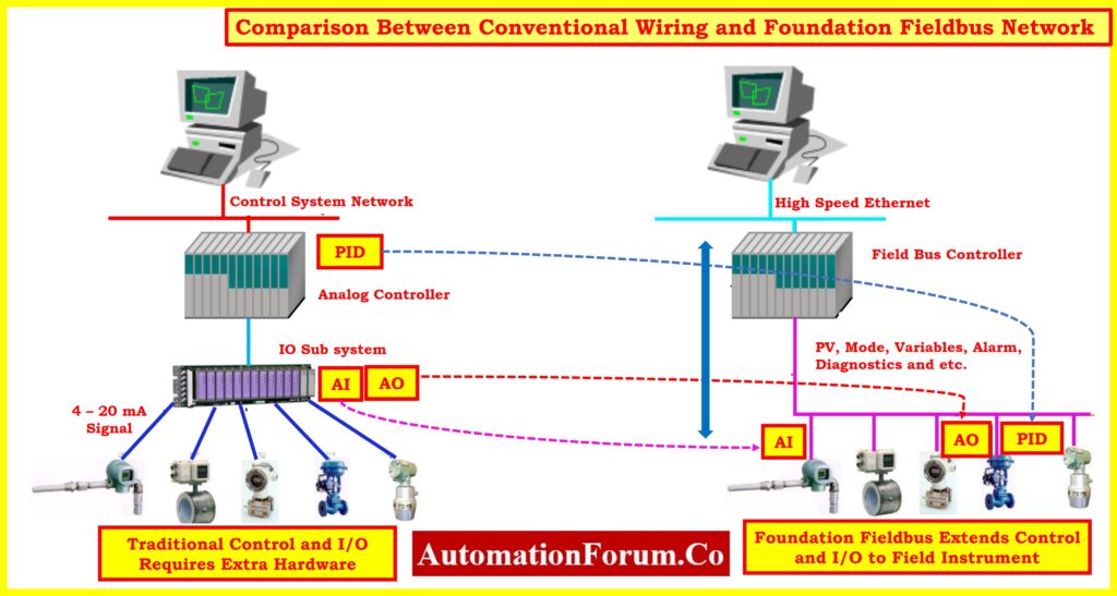
Comparison Between Conventional Wiring and Foundation Fieldbus Network
A traditional Distributed Control System uses two wires to connect to a field instrument. The wires provide electrical power to a device. The device communicates its measured data to the DCS controller by changing the current from 4 to 20 mAmps. The controller collects data from several devices, does computations, and transmits commands to the actuator by altering the current. Refer below Figure.
Figures depict traditional DCS wiring in a panel versus Foundation Fieldbus network.
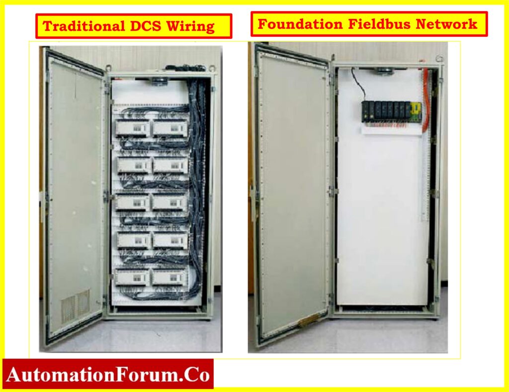
Using Foundation Fieldbus reduces the need for terminations, I/O cards, home run wiring, and control room panel space compared to standard DCS installations.
Below table summarizing the comparison between Conventional Wiring and Foundation Fieldbus Network:
Conventional Wiring vs Foundation Fieldbus Network
| Aspect | Conventional Wiring | Foundation Fieldbus |
| Power and Communication | Two wires for power and signal transmission | Two wires for power; shared communication bus |
| Termination Points | 240 terminations | 60 terminations |
| Topology | One-to-One | Multi-drop |
| Transmission Method | 4 to 20 mA DC analog signal | Digital Signal |
| Transmission Direction | One-way | Bidirectional |
| Type of Signal | Single signal | Multiplex signal |
| Multivariable Detection | Requires separate cables for each variable | Supports Multivariable transmission |
| Errors in Data Transmission | Prone to errors due to analog-digital conversion | Rarely occurs in digital signal transmission |
| Interoperability | Difficult between devices of different manufacturers | Allows digital data exchange between devices from different manufacturers |
Various Terminologies used in Foundation Fieldbus Network System
Trunk:
- The link between the Host controller (or H1 card in the controller) and the megablock in the field, consisting of a twisted pair cable.
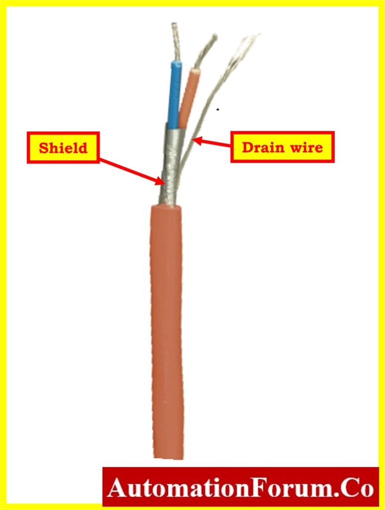
- Cable Types: A, B, C, D with different characteristics.
- Cable Description: Varying in shielding and conductor configurations.
| Cable Type | Distance (meters/feet) | Characteristic Impedance (Ohms) | Resistance (Ohms/Km) | Attenuation (DB/Km) | Description |
| Type A | 1900/6270 | 100 | 22 | 3 | Each twisted pair has shield |
| Type B | 1200/3960 | 100 | 56 | 5 | Multiple twisted pair with overall shield |
| Type C | 400/1320 | Unknown | 132 | 8 | Multiple twisted pairs, no shield |
| Type D | 200/660 | Unknown | 20 | 8 | Multiple conductor cable, no pairing of wires |
Spur:
- Similar to the trunk cable, it connects the megablock to field devices.
- Special Case: A spur cable less than 1 meter (3.28 ft.) is termed as a splice.
Megablock:
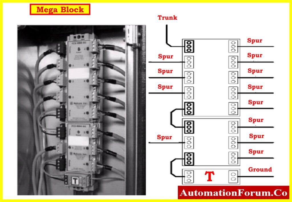
- A wiring connection block allowing termination of two trunk cables and multiple spurs to devices.
- Cascading: Multiple mega bloks can be connected by linking the trunks.
Terminator:
- An impedance-matching module used at or near each end of a transmission line in the Fieldbus network.
- Placement: Generally located at the control room end and in the junction box in the field.
Fieldbus Power Supply (Power Conditioner):
- Required for powering a Fieldbus, providing a filter between the network and power source.
- Voltage Range: Typically between 9 and 32 Volts, with about 24 Volts provided by Fieldbus power supplies.
- Current Rating: A 16 x 20 = 320 mAmp current rating is sufficient for most applications.
Surge Protectors:
- Devices diverting surge currents to earth, protecting connected equipment.
- Operation: Allows signals to pass with minimal attenuation while safeguarding against surges.
Current to Fieldbus Converter:
- Converts a standard 4 to 20 mAmps field transmitter signal into a Fieldbus-compatible signal.
Foundation Fieldbus Host:
- The Host or H1 device located in the control room, overseeing the operation of devices connected via the Fieldbus network.
Current Limiter:
- Prevents total breakdown of a segment due to spur shorts, limiting current for each device.
Repeaters:
- Optional components extending the length of a fieldbus segment or increasing the number of devices.
- Function: Provide power and a clean communication signal for the extended segment.
Intrinsic Safety Barriers:
- Supports intrinsic safety with flexibility and lower cost compared to traditional analog intrinsic safety.
- Barrier Configuration: Single barrier serving multiple devices on a single fieldbus segment.
- Note: Existing analog barriers need replacement when converting to Foundation fieldbus wiring. A combined repeater barrier with intrinsic safety functions is available.
What is the Standard for Foundation Fieldbus?
IEC 61158 Standard:
- The International Electrotechnical Commission (IEC) standard for field bus, encompassing Foundation Fieldbus, is IEC 61158.
- It defines different types of fieldbuses, with Type 1 representing Foundation Fieldbus H1, and Type 5 representing Foundation Fieldbus HSE.
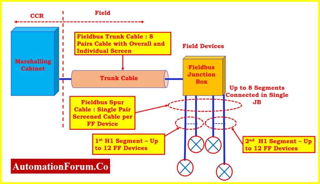
What are the Typical Components of a Fieldbus Segment?
Typical Fieldbus Segment Components:
A typical fieldbus segment, adhering to the IEC 61158 standard, consists of the following components:
Host System:
- The central controller or host system manages and controls the field devices connected through the fieldbus network.
Field Devices:
- Various field instruments and devices, such as sensors, actuators, and controllers, are connected to the fieldbus network. These devices communicate digitally using the Foundation Fieldbus protocol.
Fieldbus Junction Box:
- The fieldbus junction box is responsible for connecting multiple field devices to the fieldbus segment. It serves as a distribution point for the network.
Segment Coupler (For H1 Segment):
- In Foundation Fieldbus H1, a segment coupler may be used to link multiple segments, allowing devices on different segments to communicate.
Terminators:
- Impedance-matching terminators are placed at each end of the fieldbus segment to minimize signal reflections and ensure proper signal quality.
Power Supply (For H1 Segment):
- A power supply provides the necessary electrical power to the field devices on the Foundation Fieldbus H1 segment.
Linking Device (For HSE Segment):
- In Foundation Fieldbus HSE, a linking device may be used to connect the HSE segment to the H1 segments, facilitating communication between different types of segments.
Foundation Fieldbus Cable:
- The communication medium for the fieldbus network, usually a twisted pair cable, connects all the components within the segment.
Fieldbus Power Conditioner (For H1 Segment):
- Required for H1 segments, the power conditioner filters the power source to prevent interference with the signals on the network.
Fieldbus Terminator (For HSE Segment):
- Terminators may also be used in HSE segments to ensure proper termination of the network.
What is the Speed of Foundation Fieldbus?
- Foundation Fieldbus H1, a variant of the FOUNDATION Fieldbus protocol, operates at 31.25 kbit/s, offering bi-directional communication between field devices and the control system.