- What is an Intrinsically Safe (IS) Cable?
- Why Intrinsically Safe Cables are used in Hazardous Areas ?
- Key Features of Intrinsically Safe Cables
- What is a Non-Intrinsically Safe (Non-IS) Cable?
- Why Non-IS Cables are Unsafe in Hazardous Areas ?
- Key Differences Between Intrinsically Safe (IS) and Non-Intrinsically Safe (Non-IS) Cables
- Why Intrinsically Safe (IS) Cables Require Entity Parameter Verification
- Construction and Specification Differences
- IS Cable Loop Design – 3 Key Safety Conditions
- Typical use Scenarios
- Where Intrinsically Safe (IS) Cables are used: Industry Applications
- Why Correct Cable Selection Important
In hazardous environments, especially in industries like oil and gas, petrochemical, and pharmaceuticals, electrical safety is paramount. The risk of sparks, overheating, or arcing from electrical circuits can cause catastrophic explosions. To mitigate this, Intrinsically Safe (IS) design is implemented, and part of that design includes using the correct type of IS cable. However, not all environments require such precautions this is where Non-Intrinsically Safe (Non-IS) cables are sufficient.
Though they may look identical externally, IS and Non-IS cables serve vastly different purposes in terms of safety, compliance, and electrical performance.
What is an Intrinsically Safe (IS) Cable?
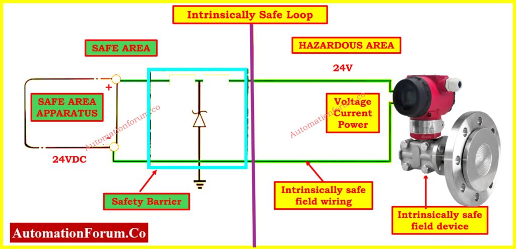
An Intrinsically Safe cable is a special type of electrical cable designed to be used in hazardous environments, where explosive gases, vapors, or combustible dusts may be present. Its purpose is to prevent any possibility of ignition from electrical faults such as short circuits, sparks, or excessive heating.
In an IS system, energy levels both voltage and current are strictly limited, so even in the event of a wiring fault or equipment malfunction, there is insufficient energy to ignite the surrounding hazardous atmosphere.
Why Intrinsically Safe Cables are used in Hazardous Areas ?
In explosive atmospheres such as:
- Oil refineries
- Chemical processing plants
- Pharmaceutical cleanrooms
- Mining operations
- Paint booths and flammable storage areas
even a tiny electrical spark could lead to a major explosion. That’s why IS-rated systems, including cables, must be installed to eliminate ignition sources entirely.
Explore why Intrinsic Safety is essential: Why Choose Intrinsic Safety (IS) for Hazardous Area Instrumentation?
Key Features of Intrinsically Safe Cables
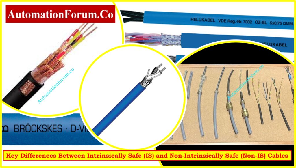
- Color Identification: IS cables are usually coated in a blue outer sheath, making them easy to identify in the field and during maintenance activities.
- Mechanical Protection: The cables are often sheathed in tough materials like polyurethane, providing excellent abrasion and chemical resistance, which is essential for industrial environments.
Electrical Parameters:
IS cables must have:
- Low capacitance (C) per meter
- Low inductance (L) per meter
- These values are critical for verifying IS compliance during loop calculations.
Compliance & Certification:
- Must conform to IEC 60079-14, ATEX, NEC 504, or CSA standards
- Suitable for Ex i certified loops (intrinsic safety protection type)
Used With:
- Transmitters
- Solenoid valves
- Temperature sensors
- Limit switches
- Other Ex i-certified instrumentation
Understand what Intrinsically Safe systems are: What is intrinsically safe system and what is its importance?
Intrinsically Safe (IS) Cable use in Instrumentation
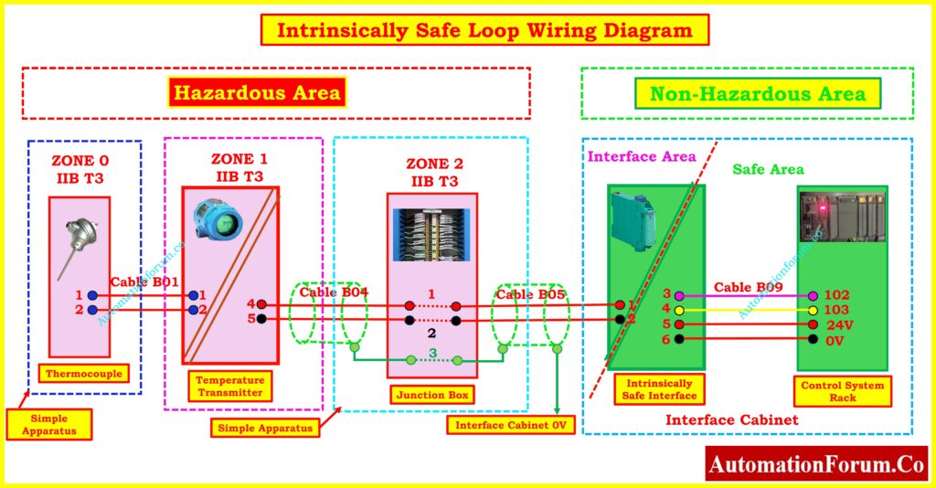
In typical IS instrumentation loops:
- The field instruments (transmitters, RTDs, etc.) are located in hazardous areas.
- The associated apparatus (barriers or isolators) are installed in safe zones, such as control rooms.
- IS cables connect these components, ensuring that any electrical energy transmitted to the field is below ignition thresholds.
Even standard instrumentation cables can be used as IS cables only if their capacitance and inductance values are verified and included in entity calculations.
Find out why NAMUR sensors are vital: Why NAMUR Sensors are Essential in Explosive and Hazardous Areas ?
What is a Non-Intrinsically Safe (Non-IS) Cable?
Non-Intrinsically Safe cables are standard electrical or instrumentation cables that are not rated for use in hazardous environments. These cables do not restrict energy and can potentially become a source of ignition if exposed to flammable gases or dust.
Discover how Safety Barriers function effectively: What is a Safety Barrier? & how does Safety Barrier work?
Why Non-IS Cables are Unsafe in Hazardous Areas ?
- These cables are not designed to prevent sparks during electrical faults.
- Overloading, short circuits, or insulation breakdowns can lead to:
- Excessive heat generation
- Arcing
- Ignition of surrounding explosive gases
- Using such cables in hazardous zones violates safety codes and can result in equipment damage, explosions, or loss of life.
Where can Non-IS Cables be used Safely?
Non-IS cables are suitable in:
- General-purpose environments (non-classified areas)
- Electrical rooms and control panels
- Office spaces, power rooms, HVAC systems
- Any location where flammable vapors or dusts are not present
These cables can carry standard voltage and current without restriction but lack protective features such as low capacitance or Ex i compliance.
Refer the below link to understand Difference Between Intrinsically Safe and Explosion-Proof
Key Differences Between Intrinsically Safe (IS) and Non-Intrinsically Safe (Non-IS) Cables
| Feature | Intrinsically Safe (IS) Cable | Non-Intrinsically Safe (Non-IS) Cable |
| Application Area | Used in hazardous (explosive) zones such as Zone 0, Zone 1, and sometimes Zone 2 | Used in safe or general-purpose areas, such as Zone 2 or unclassified locations |
| Energy Limitation | Specifically designed to limit voltage and current to levels below ignition thresholds, even under fault conditions | No such limitation; the circuit can carry full electrical potential which can result in sparking in hazardous environments |
| Entity Parameters (Ca, La, Vmax, Imax) | Mandatory to calculate during loop design; used in verifying IS loop compliance with safety standards | Not required; entity parameters are ignored since no ignition protection concept is applied |
| Color Code (Outer Sheath) | Commonly has a blue outer sheath to indicate intrinsic safety and simplify field identification and maintenance | Usually has black, grey, or standard industrial colors, with no special identification for hazard protection |
| Terminal Color Coding | Uses blue-colored terminals in junction boxes and control panels to mark IS circuits | Uses standard grey or neutral terminals with no safety-specific identification |
| Cable Segregation Requirements | Must be physically separated from Non-IS or high-power circuits in cable trays, as per project specifications and standards like IEC 60079-14 | No segregation requirements; can be routed with general-purpose cables in mixed-use trays |
| Compliance and Certification Standards | Must comply with ATEX, IEC 60079-14, NEC 504, ISA RP12.6, and other hazardous area installation standards | Complies with general wiring codes (e.g., NEC, IEC 60364), but not suitable for hazardous zones |
| System Design Complexity | Involves detailed loop validation, including barrier/isolator selection, and entity matching between field devices and associated apparatus | Simpler design process, as no intrinsic safety calculations or matching is required |
| Installation Cost | Slightly higher due to the need for validated components, segregated routing, and more rigorous documentation | Lower cost due to easier cable routing, no special loop validation, and fewer design constraints |
| Protection Method Type | Used with Ex i (intrinsic safety) protection method; designed to prevent sparks by limiting energy | May be used with Ex d (flameproof) or non-hazardous equipment; offers no energy-limiting features |
| Explosion Risk if Misused | Very low risk when properly implemented; even fault conditions won’t result in ignition | High explosion risk if used improperly in hazardous areas; cables can spark or overheat under fault conditions |
| Usage Scope | For use in instrumentation and control systems involving pressure transmitters, RTDs, level switches, solenoids in classified hazardous areas | For general electrical and instrumentation use in safe areas like control rooms, MCC panels, and offices |
| Field Identification | Easily identifiable by blue sheath and blue terminals in junction boxes | No unique visual identifiers related to safety classification |
| Entity Verification Needed? | Yes – Mandatory for IS circuit validation and approval | No entity verification or loop limitation required |
| Cable Property Verification (C, L per meter) | Yes – Cable capacitance and inductance must be considered in IS loop calculation | Not needed – Cable electrical properties are not safety-limiting factors |
Note: Using a Non-IS cable in an IS loop invalidates the intrinsic safety rating even if all other components are compliant.
Refer to the complete IEC Standards chart: IEC Standards Chart for Instrumentation and Control
Why Intrinsically Safe (IS) Cables Require Entity Parameter Verification
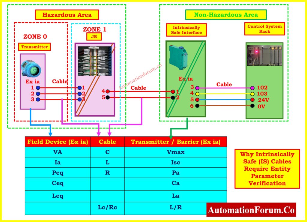
Important Parameters:
- Vmax = Max voltage the device can tolerate safely
- Isc = Max short-circuit current allowed into the loop
- Ca = Maximum allowed external capacitance at terminals
- La = Maximum allowed external inductance at terminals
These values are checked against the associated barrier or isolator specifications. If the cable’s C and L values exceed the allowance, it could store enough energy to ignite gases, defeating the purpose of intrinsic safety.
Construction and Specification Differences
IS and Non-IS cables may appear identical in terms of:
- Number of pairs (1P, 2P, multipair)
- Shielding (individual and overall)
- Armoring (steel wire, aluminum tape)
- Jacket types (PVC, LSZH, XLPE)
However, the dielectric strength, capacitance per meter, and inductance may vary significantly. IS cables are tightly specified to maintain low C and L values, ensuring they don’t store excessive energy.
Always request the manufacturer’s datasheet to verify IS compliance when selecting cables for hazardous zones.
IS Cable Loop Design – 3 Key Safety Conditions
Intrinsically Safe (IS) circuits are designed to prevent ignition of flammable atmospheres by limiting the electrical energy under both normal and fault conditions. To ensure compliance, three safety conditions must be validated during IS loop design. These conditions revolve around voltage/current limits, stored energy, and inductive behavior of cables.
Condition 1: Voltage and Current Compliance
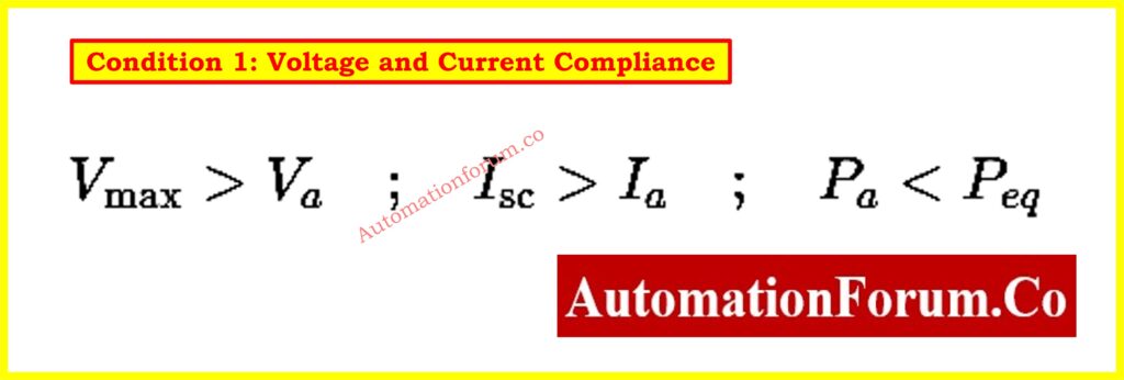
Where:
- Vmax = Maximum voltage rating of the field device (intrinsically safe apparatus)
- Va = Maximum voltage output of the associated apparatus (barrier or isolator)
- Isc = Short-circuit current rating of the field device
- Ia = Maximum current output from the associated apparatus
- Pa = Maximum power allowed into the IS device
- Peq = Maximum equivalent power that the barrier/isolator can deliver
Purpose: This ensures the device won’t be damaged or become an ignition source even during a worst-case scenario such as a line short or surge. The IS field device must be able to absorb or withstand the voltage and current that may be present under fault conditions.
Condition 2: Capacitance and Inductance Limits

Where:
- Ceq = Internal capacitance of the field device
- Ccable = Capacitance introduced by the connecting cable (μF/km)
- Ca = Maximum allowed external capacitance at device terminals
- Leq = Internal inductance of the field device
- Lcable = Inductance introduced by the cable (mH/km)
- La = Maximum allowed external inductance at device terminals
Purpose: This condition limits the total stored electrical energy in the circuit. If the combined capacitance and inductance exceed the device’s limits, even a small current interruption could generate a high-energy spark, leading to ignition in hazardous areas.
Tip: Cable specifications typically include C and L per meter. Multiply by total length and compare against the allowable values.
Condition 3: L/R Ratio Validation (Loop Reactance Check)
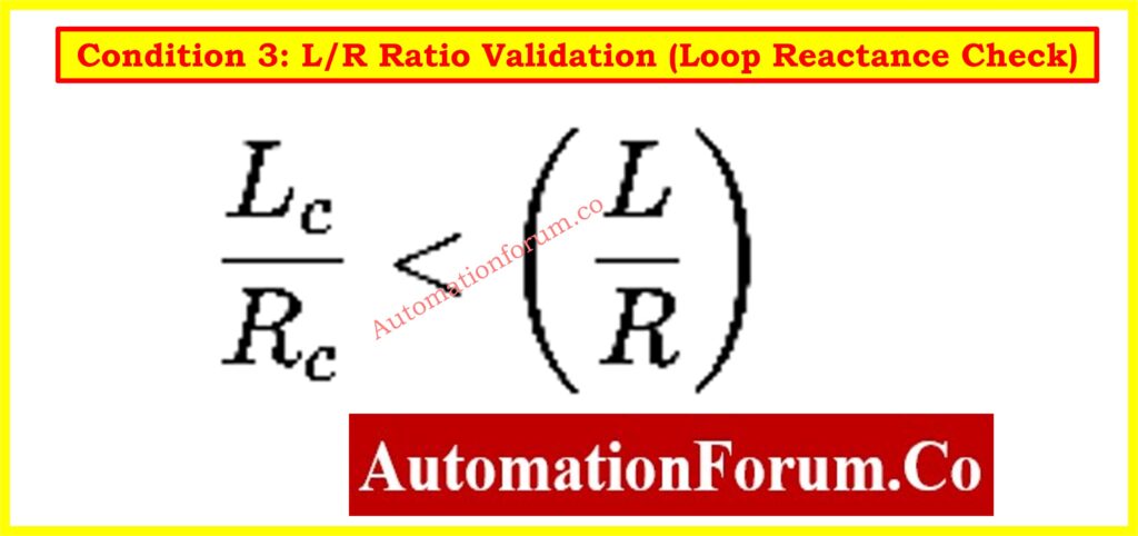
Where:
- Lc = Inductance of the cable (mH)
- Rc = Resistance of the cable (Ω)
- L/Rallowed = Maximum L/R ratio permitted by the associated apparatus (barrier/isolator)
The L/R ratio represents the time constant (τ) of the cable’s inductive circuit. A high L/R value means the circuit can store and release energy over a longer time, increasing the chance of producing dangerous sparks during open-circuit or switching conditions.
In other words, lower L/R = faster energy dissipation, which is safer.
This validation step compares the actual cable’s inductive behavior against the threshold defined in the Ex i approval data of the associated apparatus.
How this Affects Cable Selection
If your cable’s L/R ratio is below the allowed L/R of the barrier:
- You don’t need to worry about detailed L and C values
- The inductance of the cable can be ignored in calculations
- Longer cable runs are possible
If L/R exceeds the allowed limit:
- You must go back and check Condition 2 in full
- Cable length may need to be reduced, or a different cable type selected
Example:
Suppose:
Barrier allows max L/R = 150 μH/Ω
Selected cable:
- Lc = 0.75 mH
- Rc = 10 Ω
Then:
Lc / Rc=0.75/10=0.075 mH/Ω =75 μH/Ω
Since 75 < 150 μH/Ω, Condition 3 is satisfied, and you can ignore the inductance in further IS loop calculations.
Summary of Condition 3 Benefits
- Simplifies loop validation if passed
- Enables longer cable runs in the field
- Reduces need for expensive low-capacitance cable
- Improves flexibility during installation and expansion
Remember: L/R checks are not always mandatory but passing this condition makes the IS design significantly easier.
Typical use Scenarios
IS Circuit – Zone 0/1
- Devices: Ex i certified transmitters, limit switches, RTDs
- Barrier: Zener or Galvanic isolator installed in safe area
- Cable: IS-rated, blue sheath
- Routing: Physically separated from high-voltage and non-IS cables
Designed for high-risk explosive zones, where even minor energy faults could cause ignition.
Non-IS Circuit – Safe Area or Ex d Zones
- Devices: Flameproof or general-purpose transmitters
- No barrier needed
- Cable: Standard instrumentation cable
- Routing: Can be mixed with other circuits
Ideal for safe or lightly hazardous zones where Ex d or other protection methods are used.
Refer the below link to Learn how to perform Intrinsic Safe Calculation for Instrumentation Design Engineers
Where Intrinsically Safe (IS) Cables are used: Industry Applications
| Industry | Typical Hazardous Areas | IS Cable Usage |
| Oil & Gas | Refining units, offshore rigs | Pressure, flow, and level transmitters |
| Petrochemicals | Reactor zones, storage tanks | IS temperature sensors, solenoid valves |
| Pharmaceuticals | Solvent mixing areas | Ex i weighing and dosing systems |
| Paint Shops | Spray booths, curing ovens | Position sensors, switches |
| Mining | Underground operations | Alarm systems, gas sensors |
In these sectors, failure to comply with IS cable specs can result in legal violations, insurance issues, or catastrophic failures.
Why Correct Cable Selection Important
The choice between an IS cable and a Non-IS cable isn’t just a matter of installation preference it’s a matter of safety, compliance, and liability. In hazardous locations, only IS-certified systems, including the correct cabling, should be used to prevent fires or explosions.
Always:
- Review the hazardous area classification
- Select Ex i-approved devices and IS-rated cables
- Perform entity parameter calculations
- Maintain physical segregation of IS and Non-IS cable
- IS cables are mandatory for intrinsic safety compliance in hazardous zones
- Cable capacitance and inductance must be within specified limits
- Color codes (Blue for IS) are critical for field identification and troubleshooting
- Must be used with approved barriers and IS devices
Using a Non-IS cable in an IS loop voids the protection and can lead to catastrophic failure. Always verify cable specifications before installation.
 and Non-Intrinsically Safe (Non-IS) cables. Understand their uses, compliance standards, safety features, and why choosing the right cable is vital in hazardous environments.)