Table of Contents
- Purpose and scope:
- Tools required for maintenance on struck control valve:
- Safety
- To solve any control valve-related issues, use the advice in this article.
- If Valve not operating
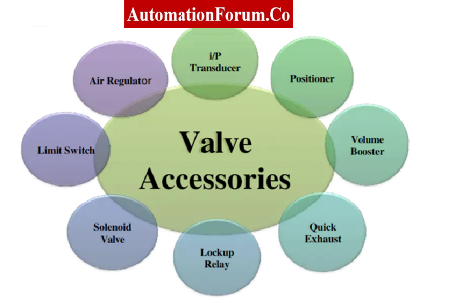
- What are major parts of control valve?
- Critical Components of the Control Valve are Subjected to Inspection
- If Valve has Stiction
- Sign and Symptom
- How to repair a control valve with stiction issue
- Ways to prevent stiction in a control valve
- Recording Stroke checking of the installed control valve after overhauling
- Sample stroke check report
Purpose and scope:
The maintenance and troubleshooting of struck control valves are covered in detail with guidelines in this content.

Tools required for maintenance on struck control valve:
- Necessary hand tools.
- Multimeter.
- HART communicator of handheld configurable communicator if it is an electronic smart positioner.
- Loop calibrator / multipurpose calibrator for feeding 4 to 20 mA signal.
- Soft Cloth for cleaning.
- Standard fittings with tubing setup for checking actuator movement.
Safety
- For basic safety and general rules, as well as information on calibrating/troubleshooting operations in process industries, please refer to the link provided below.
- Request that the panel operator set the controller to manual mode for the control loop and MOS for the ESD loop.
- Verify the isolation of the control valve from the process.
To solve any control valve-related issues, use the advice in this article.
If Valve not operating
- The first step is to do a visual inspection of the control valve as well as all of its associated accessories.
- Perform a thorough inspection for any physical damage or air leaks. If there were any problems detected, then fix them.

- Make sure the constancy of the air supply to the control valve.
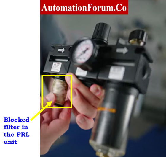
- Check the air supply leading from the air filter regulator (FRL unit) to the valve positioner or solenoid valve, depending on which one is available.
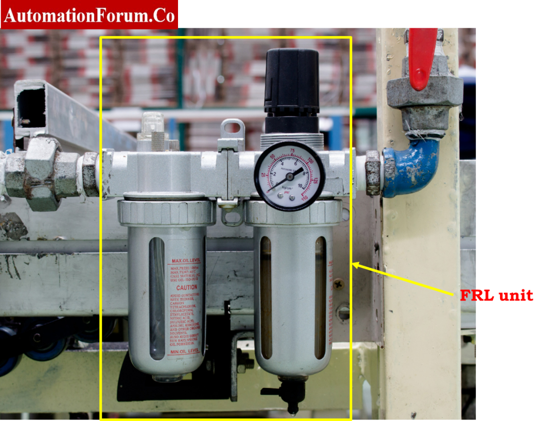
- Now check the FRL unit set pressure; it must match the value specified in the datasheet for the control valve.
- The valve will move very slowly if the air supply pressure is less than the advised value.
- The actuator may be damaged if the air supply pressure is higher than the advised pressure.
- Therefore, adjust the air pressure to the required levels.
- If there is no air supply, then examine the condition of the isolation valve that is located in the air supply header.
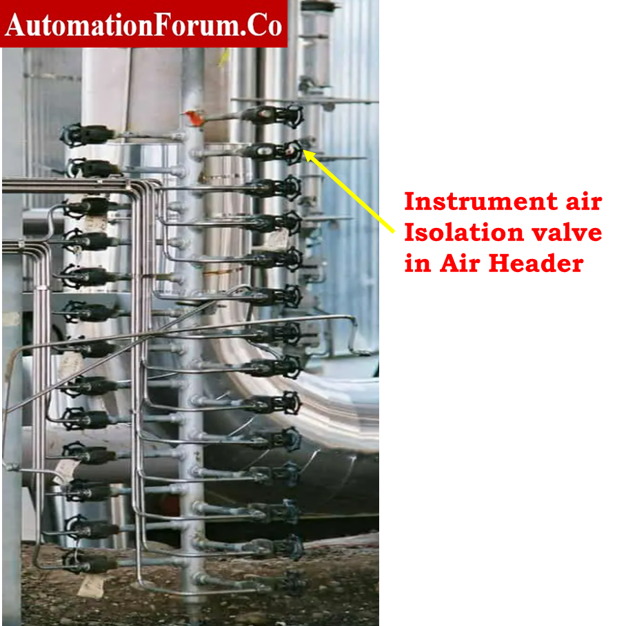
- If the isolation valve is confirmed to be closed, open it.
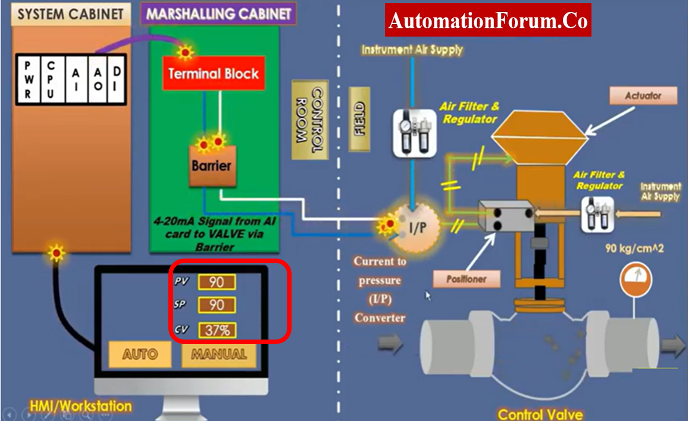
- From the control room, issue the order to open or shut the control valve depending on the field circumstances.
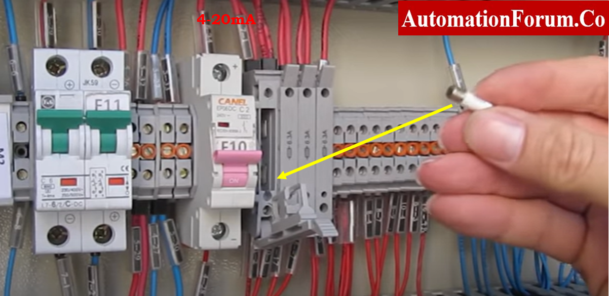
- In the event that the valve remains stationary, verify the current signal on the electro pneumatic positioner or I to P convertor.
- If the current signal is absent, carefully examine the cable connections by referencing the loop drawing on the field side and marshalling cabinet side.
- Additionally, inspect the marshalling cabinet‘s fuse condition. Replace the fuse if it is confirmed to be blown with one of equal rating. Check the cable condition if the issue is still present.
- Checking the cable’s resistance will help you figure out what is wrong with it.
- If the cable pair is determined to have a problem, a new, good cable pair should be used in its stead.
- This action will assist in getting the control valve’s signal.
- To operate the control valve and perform the valve stroke checking test, provide a 0 to 100% instruction from the control system. Additionally, when doing the stroke test, check the control valve feedback on the displays.
- If the system command says that the valve stroke is fine, but the feedback is not fine, then the feedback setting or configuration needs to be changed.
- There are two different kinds of valve feedback concepts here. One has open feedback and closed feedback, while the other has full analogue feedback from 0% to 100%. (depends on your control valve design). Control valve calibration will often resolve a problem with analogue feedback if it exists.
- Check for interlocks, forced analog output signals in the program and permissive conditions from the control system, since the control system may not transmit the order to the valve if the logic is not correct, and control valve does not make any stem movement.
- Performing the calibration will address any problems with the control valve stroke.
- Check the stroke one again after calibrating. Check the mA to the valve positioner’s input if there is still a problem with the stroke.
- Give many commands to the control system, then check the field mA in I to P converter or electro pneumatic positioner
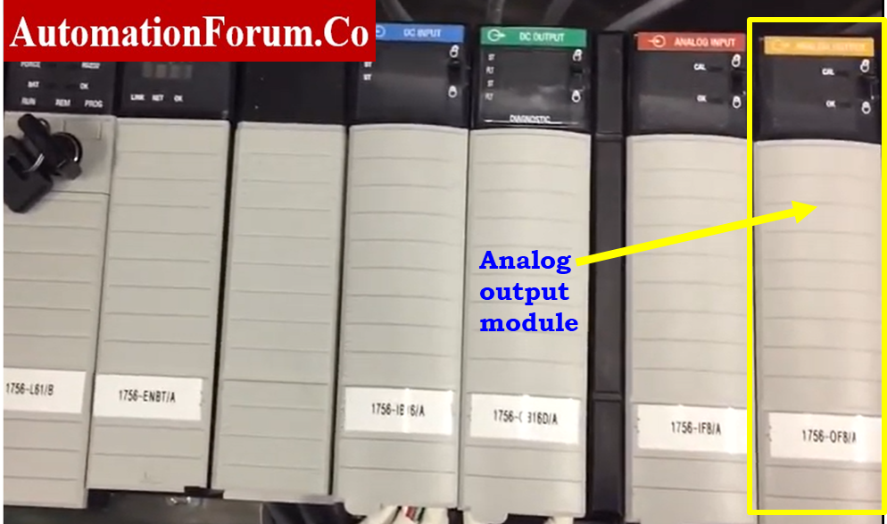
- The control system analogue output channel can have a problem. Then address the problem and replace the faulty analog I/O module.
- Conduct a test to determine the operational condition of the air filter regulator.
- Determine the condition of the volume booster, airlock relay, trip valve, vent port and solenoid valve if any of these were added subsequently.
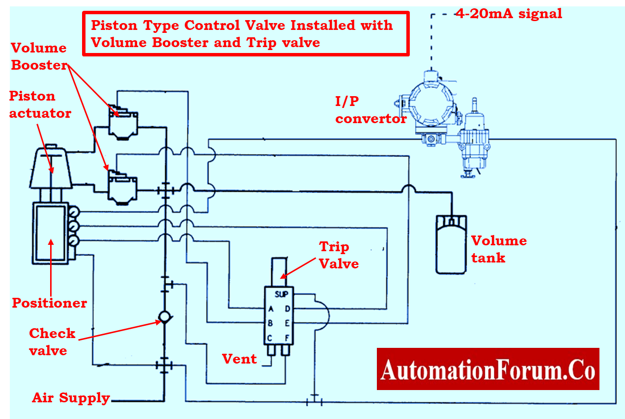
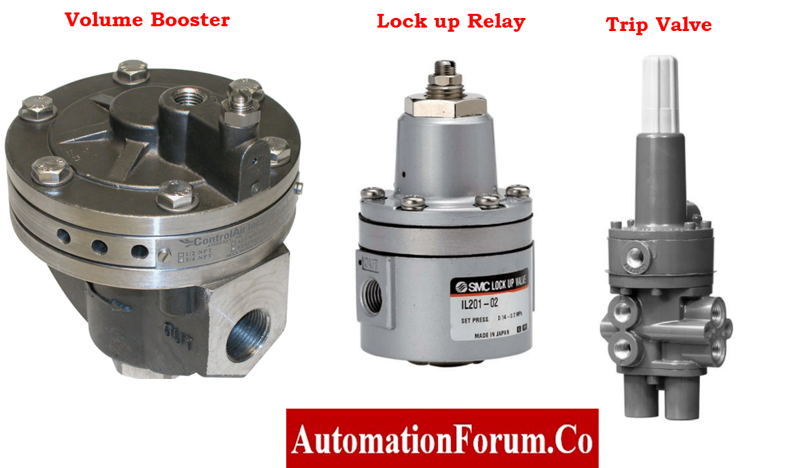
- Check to see that there shouldn’t be any issues with their being blocked. Additionally, replace them if any significant problems were identified.
- Make sure the whole tube line is clear of the choke.
- Check to make sure there is no obstruction in them. Replace them if any major issues are identified.
- Verify the I/P converter’s state of operation.
- Verify the output of the positioner.
- If the output is not arriving from the positioner, calibrate and repair the positioner.
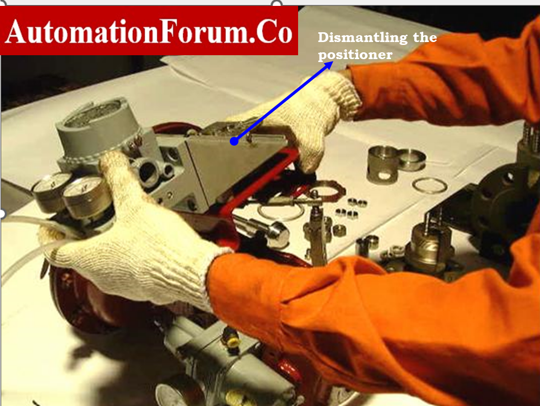
- Every time a control valve is refurbished, a positioner calibration is performed. Every model may have different procedures. Before doing any calibration operation, it is required to inspect the following:
- O-rings, moving components (cam, lever, spring, etc.)
- Gauges for diaphragm pressure
- Cracks
- Flapper and nozzle
- Air leaks from the supply outlets, signal, and output.
- Electric coils and electronic cards in I/P positioners must always be kept dry and free from moisture.
- If there is any doubt about the functionality of the valve positioner, then the positioner should be replaced and the calibration should be performed. After the calibration is complete, you should check the control valve’s stroke once again.
- If none of the above possibilities are true, the issue will be on the actuator or valve body side.
- If the functioning of the control valve is still problematic, remove all of the tubing and test the movement of the control valve by supplying external air directly to the actuator. This should be done only if the problems continue.
- To relieve the stuck state, manually operate the valve.
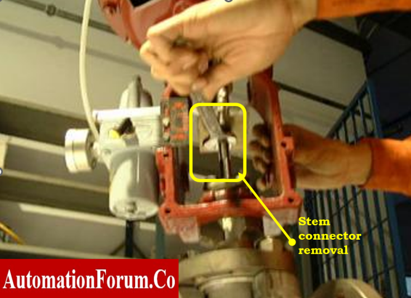
- To determine the source of the issue, remove the actuator stem and valve stem connection and assess how the actuator functions.
- Verify whether or not the actuator is passing. The majority of control values include an air-passing port that may be used to check for diaphragm deterioration.
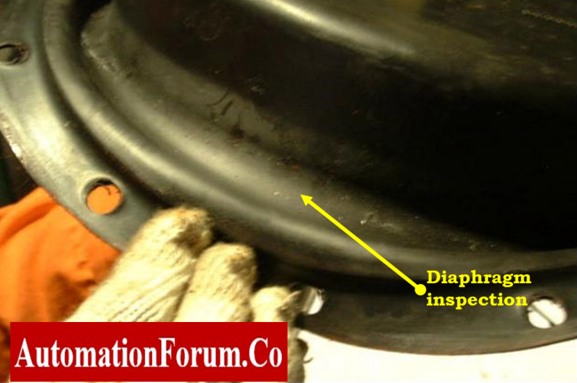
- Perform an overhaul on the actuator if it is experiencing passing problems.
- Remove the cap and examine the plate, spring, and other components within the actuator control value if the actuator is not functioning normally.
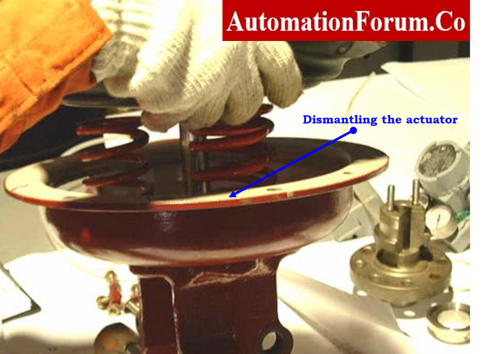
- Inspect all the components inside the actuator.
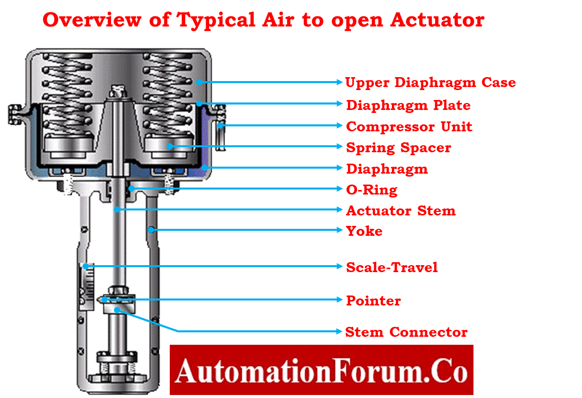
What are major parts of control valve?
Critical Components of the Control Valve are Subjected to Inspection
- Actuator Diaphragm
- Actuator Shaft
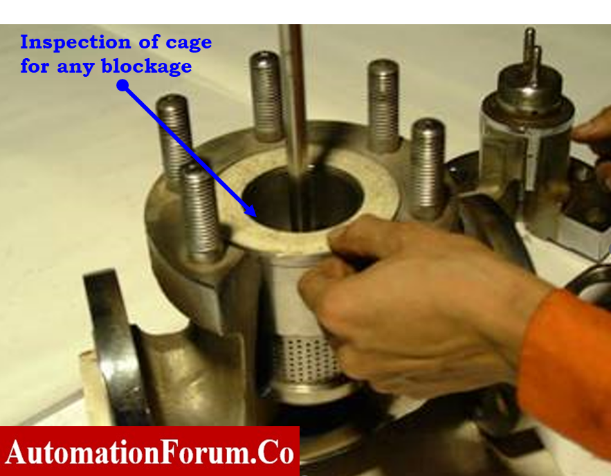
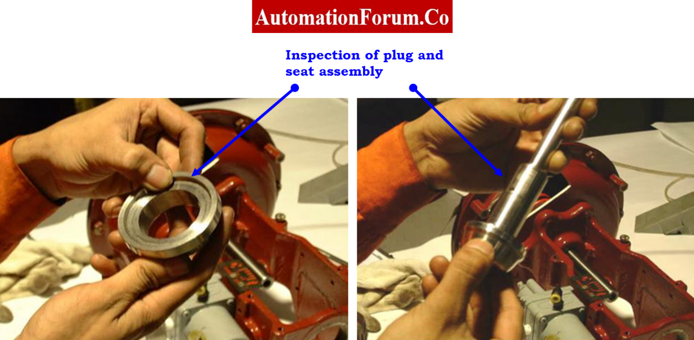
- Trim Components (Plug, Seat, Cage and Stem)
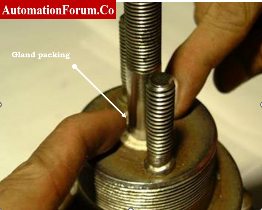
- Gland packing Box on Bonnet
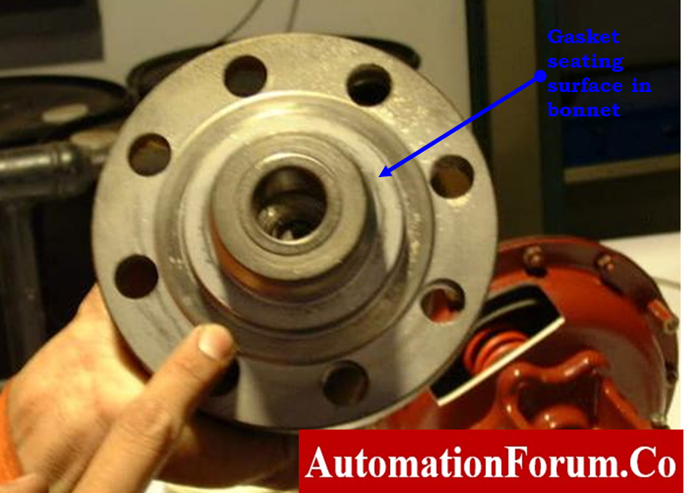
- Gasket Seating Surface
- NDT Test for Body Wall
- Valve Positioner Condition
- Valve body Stud Bolts and Nuts
- Actuator Spring
- Hand-Wheel (if installed)
- Flange Gasket Surfaces
- After overhauling the actuator, apply the air pressure now in accordance with the bench set specified on the control valve’s nameplate or datasheet. The control valve should operate smoothly.

- Check the control valve’s fail action to make sure it’s working properly.
- If the valve movement is still slow or becomes stuck, disconnect the actuator from the valve body.
- Recheck the actuator’s reaction. If everything is confirmed to be in order, the valve body side will have a problem.
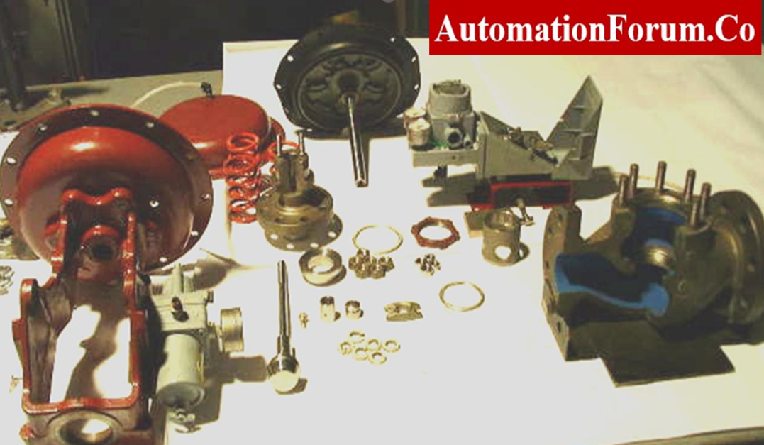
- To examine and overhaul the valve body, remove it.

- If the control valve has linear movement. Mark the control valve appropriately before dropping it.
- By the way, take the valve body off and examine the inside components for damage. In the event that there is any damage, you should replace it.

- Reinstall the control valve after overhauling of valve body and do another stroke check after the overhaul.
Why does a control valve get stuck?
If Valve has Stiction
- Another issue that often shows itself in the control valve loop is referred to as “stiction is a combination word that combines the words “stick” and “friction.”
- “This is a condition that retains the valve in its constant positions and does not let it to travel about freely like a Dead band.
- When a stiction problem exists, the movement of the valve requires greater effort.
- This increased force may also cause the valve to overshoot its position and its process setpoint like the Dead band, which causes the valve to get stuck in a new or incorrect position.
- Stiction is often seen in control loops that are in preset mode and exhibit a continuous cycle pattern in controller output and a square wave pattern in process variables, resulting in process disruption and valve tears.
Sign and Symptom
- There might be an issue with the internal valve becoming sticky.
- Actuators of an inadequate size.
- The Viscosity of the Medium.
- A Very Harsh Shutoff.
- In stiction, the control valve will never reach the desired set point that was intended for it.
- The valve continues to stick in various positions.
- The controller output was set to reverse the direction, and the whole process runs in the opposite way.
- Stiction causes a loop cycle; the output movement of the control valve will resemble a saw-tooth wave, while the process may resemble a square wave or irregular sine wave.
How to repair a control valve with stiction issue
- The valve actuator and positioner must be correctly sized to change the force necessary to move the valve in order to address issues with stiction in the valve.
- Determining if the valve’s air pressure is within the range specified by the control valve’s manufacturer.
- Examine the valve packing gland’s torque.. Inspect the gland packing.
- The internals of the valve should also be visually inspected for signs of scaling, scarring, or general wear and tear, and the valve should be replaced as required.
- Examination of the seating surface of the gasket on the valve bonnet
- Check to see if there is any fouling on the valve stem plug and seat assembly. If you are unsure about anything, you should get a new one and replace the old one.
- Locating the valve, verifying its orientation, and determining if the valve is less susceptible to stickiness as a replacement alternative for high-performance butterfly valves may help reduce the issue of stiction caused by the use of viscous or sticky process fluid.
Ways to prevent stiction in a control valve
- A few issues that need to be solved in order to prevent frequent valve sticking are what create the stiction or binding problem in valves.
- Stiction is mostly caused by packing that is either too tight or broken; This packing must be changed out with a fresh set, and the packing’s flange must be tightened with only one turn of the wrench until it is hand tight.
- Also inspect the surface wall of the gland packing wall.
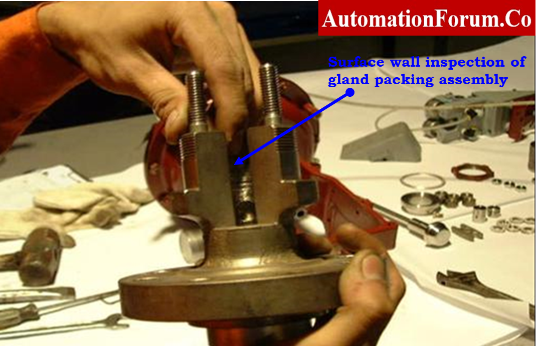
- By passing your hand over the whole surface, you may check for any scratches or rough surfaces and determine whether it is straight.
- The valve should be properly cleaned, smoothed with fine grinding paste, and installed if there are any suspected regions of uneven alterations.
Recording Stroke checking of the installed control valve after overhauling
- Apply input corresponding to 0 %, 25 %, 50 %, 75 % and 100 % according to the control valve in the upscale and downscale direction from the test standards.
- Calibration must be done if the output value does not fall within an acceptable range. All the output values are within acceptable limits (+/- %), then further calibration is not required.
- Record the resultant output values in the as found / as left column of blank stroke check report.
- Verify the function of the condition of the volume booster, airlock relay, trip valve and solenoid valve if any of these were added subsequently.
Sample stroke check report
The image that follows demonstrates that the control valve’s sample report of calibration/stroke check was performed using loop calibrator as the reference.
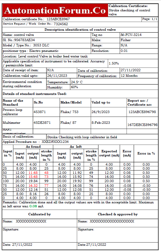
The following link provides access to a downloaded file of the excel template used in the preparation of the stroke check report for control valve.