- What is Stroke Checking of Control Valves?
- Purpose and Scope of Control Valve Stroke Checking
- Tools Required for Control Valve Stroke Checking
- Safety Precautions Before Stroke Testing
- Control Valve Stroke Checking Setup
- Control Valve Stroke Checking Procedure (Step-by-Step Guide)
- Stroke Checking Procedure for SMART Positioner (Using HART)
- Common Errors Encountered During Control Valve Stroke Checking
- Recording and Reporting Stroke Check Results
- Sample Stroke Check Report Template
- Common Symptoms That Indicate a Control Valve Needs Stroke Checking
- FAQ – Control Valve Stroke Testing, Diagnostics, and Functionality
What is Stroke Checking of Control Valves?
All control valves need to be stroked after some time in service. This is due to the fact that the valve is a mechanical mechanism that has physical components. These components must constantly be in excellent functioning condition in order to prevent the valve from failing.
Stroking the valve is the term used to describe the process of determining whether or not a control valve is functioning properly.
With the use of this exercise, the valve’s parts may be tested for functionality, allowing for quick identification and prompt correction of any issues.
The frequency of proof tests is mandated by SIS requirements for the final control element of a safety system. During the stroke checking, a part of the valve’s full range of motion is used to make sure it isn’t stuck and to find other dangerous problems. It tests the control valve to make sure that it will work and move to its safe position if safety appears to require it.
Purpose and Scope of Control Valve Stroke Checking
This procedure provides stroke check instructions for control valves calibrated with standard reference weights in the workshop.
Tools Required for Control Valve Stroke Checking

- Necessary hand tools.
- Multimeter.
- Hart communicator of handheld configurable communicator if it is an electronic smart positioner.
- Loop calibrator / multipurpose calibrator for feeding 4 to 20 mA signal.
- Soft Cloth for cleaning.
Safety Precautions Before Stroke Testing
- For basic safety and general rules, as well as information on calibrating operations in process industries, please refer to the link provided below.
- Request that the panel operator set the controller to manual mode for the control loop and MOS for the ESD loop.
- Verify the isolation of the control valve from the process.
Control Valve Stroke Checking Setup
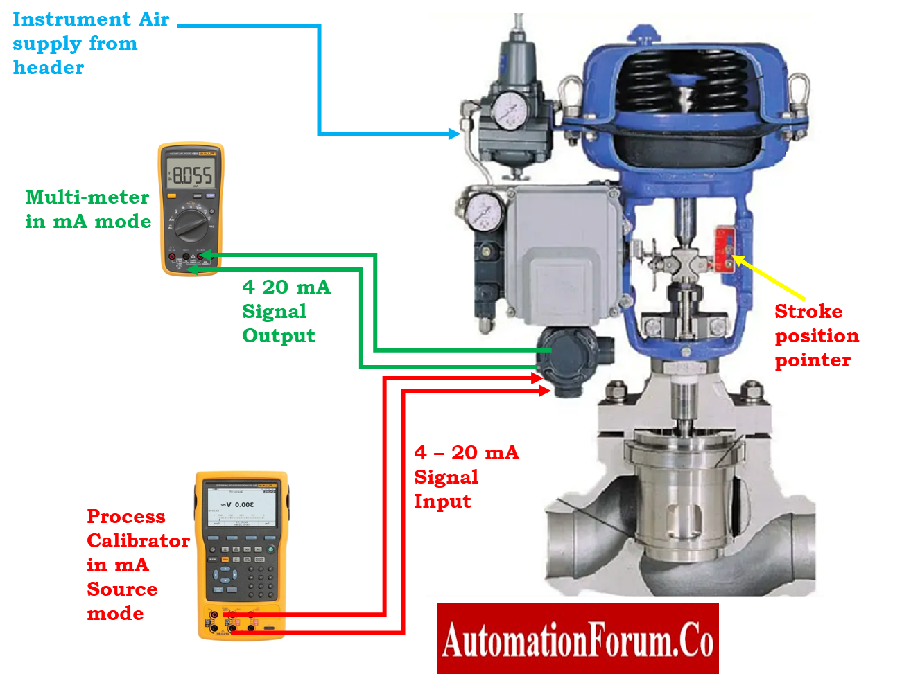
- Assume that the valve is a pneumatic one that is actuated by 4-20mA.
- Additionally, it features a valve position feedback output that is a 4-20mA signal.
- Connect the control valve as well as all of its components according to the connection diagram.
Learn the Complete Control Valve Calibration Procedure: Control Valve Calibration Procedure
Control Valve Stroke Checking Procedure (Step-by-Step Guide)
- Ensure that the air supply pressure can be reached by the Regulator at all times.

- Adjust the regulator until the pressure meets the specifications shown in the datasheet for the Valve positioner.
- Remove and insulate the analog signal output wire and analog signal input from the control terminal box.
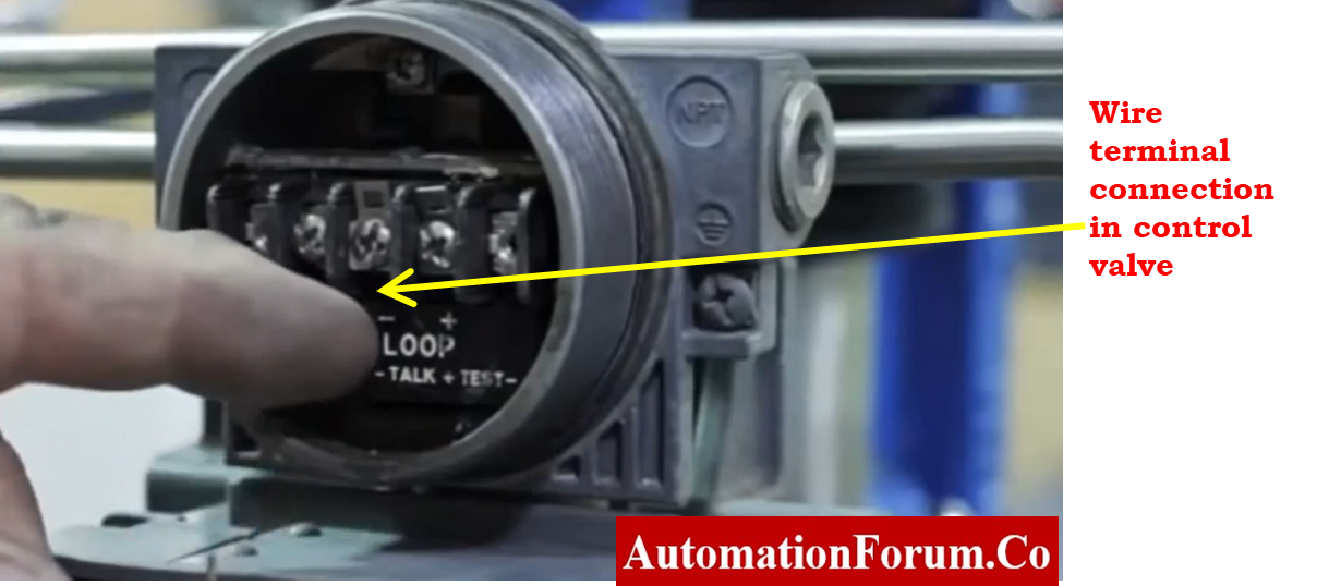
- Connect the loop calibrator (mA source) to the control valve terminal.
- Connect the multimeter to the control valve’s output line for valve position feedback in the mA mode.
- Select the mode in the Loop Calibrator (mA source mode) such that it supplies the positioner with the current input signal (4-20mA).
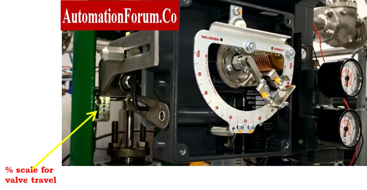
- Set the calibrator at 4mA. The control valve will indicate that it is in the 0% position. May use the scale on the control valve to check the valve’s position.
- The valve also includes a 4 to 20 mA output that shows valve position feedback.
- In order to determine this valve position feedback, we attached a multimeter.
- The valve position feedback range is 0 to 100%, which corresponds to 4 to 20mA. The multimeter in this situation will display 4mA.
- Examine the movement of the stem. It should be smooth and has to be in the minimum position.
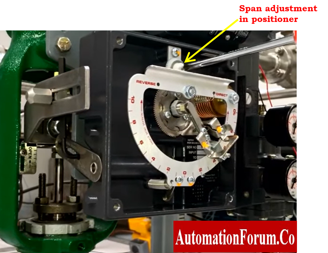
- Carefully release the locknut for zero and span adjustment if there is any error.
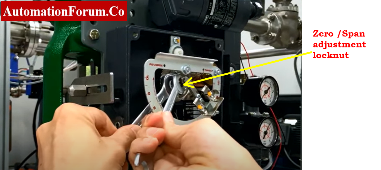
- Then zero calibrating screw in the positioner needs to be adjusted.

- Now raise the current (mA) in the calibrator all the way up to 20mA from its previous setting of 4mA.
- Check the position of the control valve stem. It should be at the 100% mark on the control valve scale. If there is any deviation from this, adjust the span screw on the positioner.
- Confirming the linearity of the control valve by applying 0%, 25%, 50%, 75%, and 100% of the 4 – 20mA signal and noting the corresponding stroke of the valve at each of these percentages.
- Now, we tested the control valve in an upward direction from 4 to 20 milliamps. Now repeat the procedure in reverse, decreasing in stages from 20 mA to 4 mA.
- The calibration locknut should be carefully tightened.
- Normalize the field wire connection of both analog input and output signal of control valve.
Stroke Checking Procedure for SMART Positioner (Using HART)
- We are able to calibrate the SMART Control Valve using a HART communicator.

- Provide the supply pressure in accordance with the valve’s nameplate specifications.
- Connect the valve positioner and the HART communicator, then type 0% in the valve simulation command and watch the valve position.
- Enter 25%, 50%, 75%, and 100% in the HART communicator in a similar manner, then watch the valve stem travel position as needed.
- To confirm the valve travel position, look for a manual scale (0% to 100%) with a pointer on the valve.
- Verify the signal’s state and remove any simulations and forces that were applied before the release the control to operation.
Explore Step-by-Step Calibration Procedure for Motorized Control Valves: Calibration Procedure for Motorized Control Valve
Common Errors Encountered During Control Valve Stroke Checking
Hysteresis
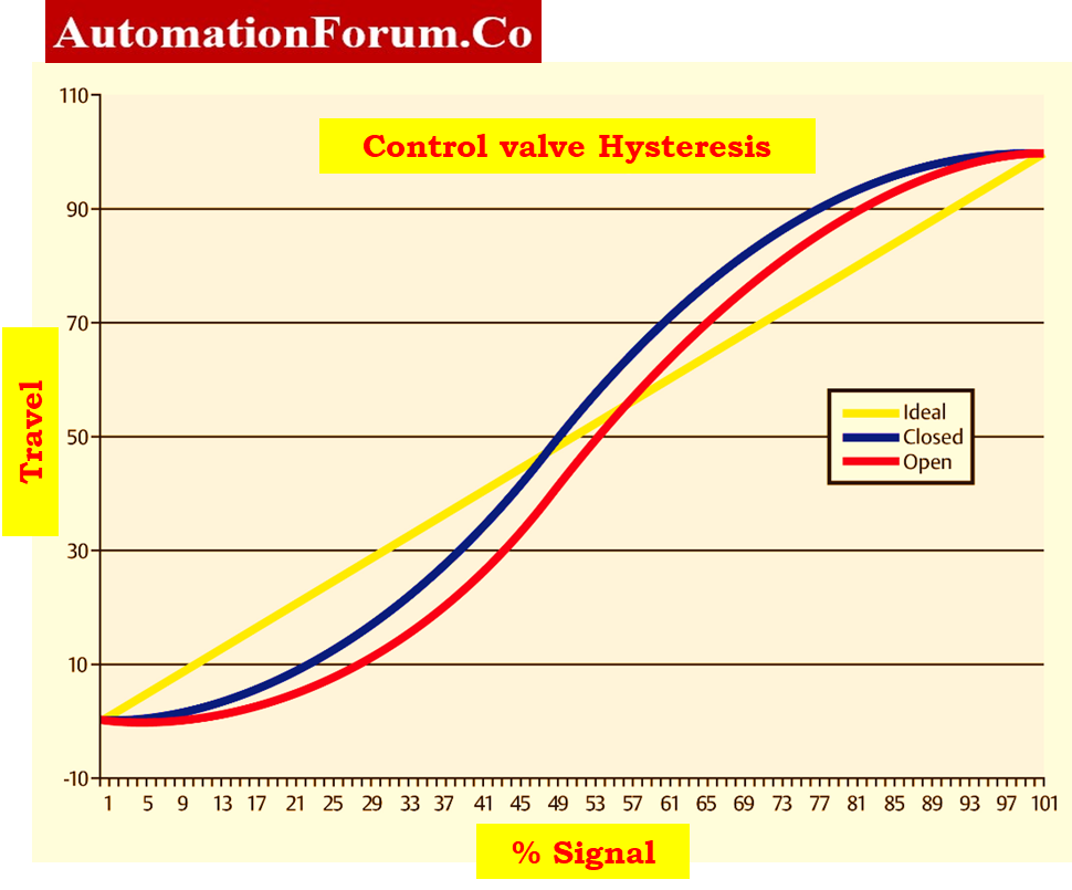
- Hysteresis, as it relates to valves, is the difference between the position of the valve during the upstroke and the position during the down stroke for any given input signal.
- In order for it to be real hysteresis, the valve must always be in motion. The most frequent source of hysteresis in valves is a high level of static friction.
Deadband
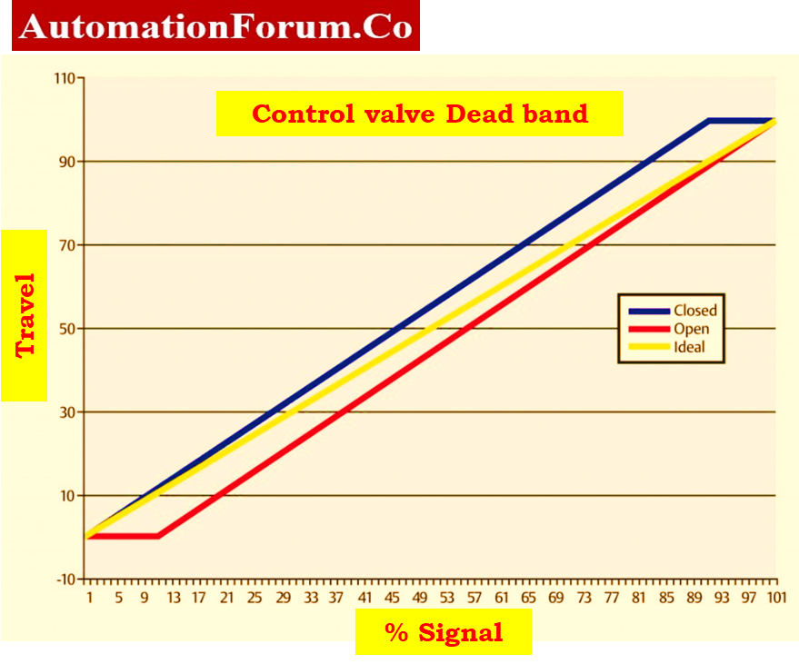
- On the other side, a deadband is a period of complete immobility that often follows a valve direction shift.
- If you can visualize a pin and slotted linkage.
- The pin is forced against the side of the slot when the actuator moves in one direction, moving the valve.
- Prior to the valve changing direction when the actuator does, the pin must push against the opposing side of the slot.
- If there is a lot of play in the slot, there will be a time when the valve does not move.
Linearity Issues
The linearity of a valve is proportional to the degree to which the graph of travel Vs signal is similar to a straight line.
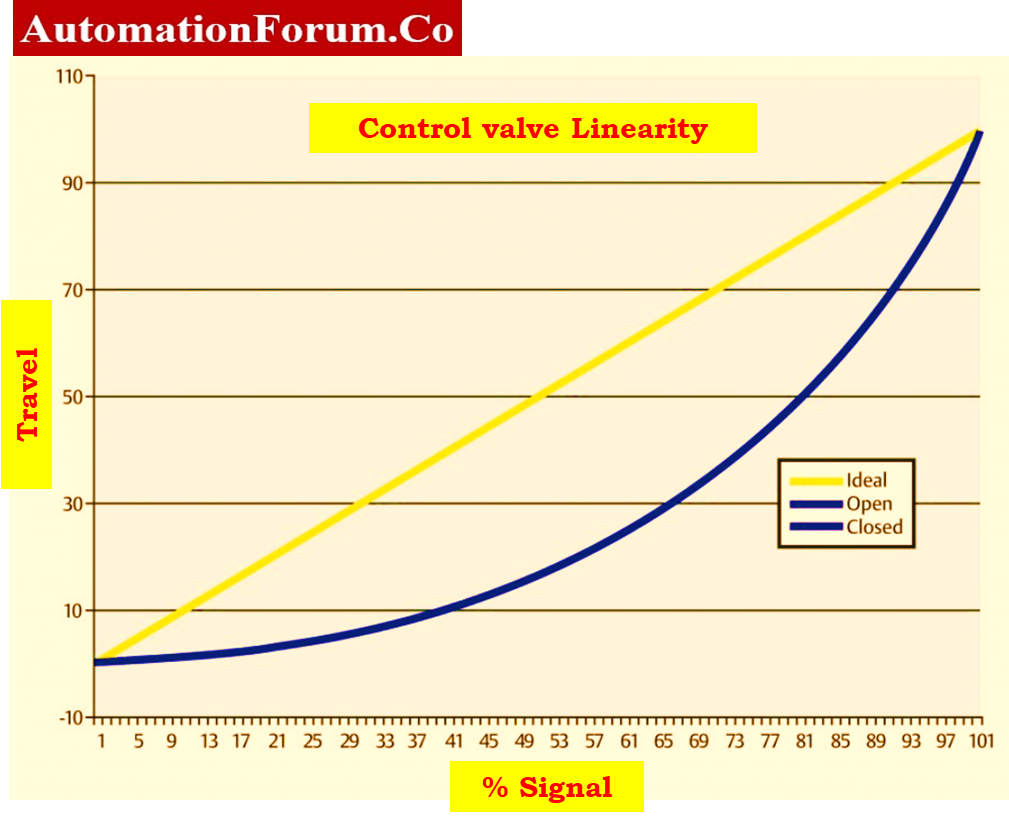
- To maintain process control, the control valve must respond to commands in a linear way.
- The controller output becomes disorganized as a result of the valve stem’s erratic movement.
- The potential reasons are listed below.
- It is possible to remove or loosen the location transmitter link. It caused the positioner to get the incorrect signal.
- This issue could be resolved by calibrating the positioner.
- Check the I/P converter’s accuracy. Replace it even if the issue is not resolved.
Follow the Loop Checking Procedure for Motor Operated Valves (MOVs): Loop Checking Procedure for Motor Operated Valve(MOV)
Recording and Reporting Stroke Check Results
- Apply input corresponding to 0 %, 25 %, 50 %, 75 % and 100 % according to the control valve in the upscale and downscale direction from the test standards.
- If the result of the output value is not within an acceptable limit, then calibration must be performed. All the output values are within acceptable limits (+/- %), then further calibration is not required.
- Record the resultant output values in the as found / as left column of blank stroke check report.
Understand the Safety Valve Testing and Calibration Procedure in Detail: Safety Valve Testing and Calibration Procedure
Sample Stroke Check Report Template
The image that follows demonstrates that the control valve’s sample report of calibration was performed using loop calibrator as the reference.
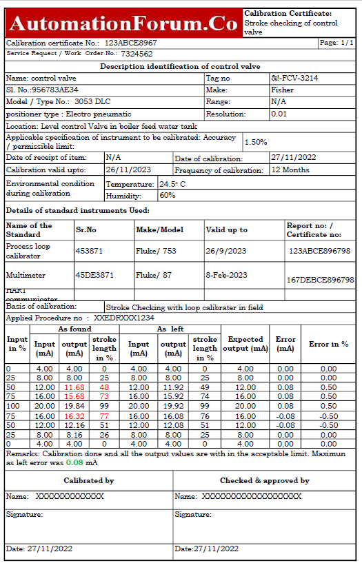
The following link provides access to a downloaded file of the excel template used in the preparation of the stroke check report for control valve.
Master the Calibration Procedure of a Control Valve Positioner: Calibration Procedure of Control Valve Positioner
Common Symptoms That Indicate a Control Valve Needs Stroke Checking
Control valves present various warning indications before failure, and identifying them early helps to avoid downtime.
Common Symptoms:
- The valve does not respond instantly when a 4-20mA signal is applied.
- Jerky or jumpy stem movement suggests stiction or friction.
- Slow opening/closing time relative to the nameplate values.
- Valve stops moving at specific travel percentages.
- Excessive air consumption from diaphragm or actuator leakage.
- Hunting or oscillation in the control loop.
- Mismatch of setpoint and actual location feedback
- Noisy actuator movement due to mechanical wear.
These symptoms indicate that the valve is no longer functioning properly and requires a stroke check before further usage.
FAQ – Control Valve Stroke Testing, Diagnostics, and Functionality
What is the stroking time for a control valve?
Stroking time is the amount of time it takes for a control valve to go from one extreme position to the other in response to a control signal. This usually means going from fully closed to fully open or the other way around. This is a key factor that shows how rapidly a valve can respond to changes in the process, which affects the overall accuracy and responsiveness of the control system.
How do you test a control valve?
We inspect control valves to make sure they work properly and keep process conditions exactly where they need to be. Testing that is done as a matter of course includes:
- Visual Inspection – Looking for damage, wear, corrosion, or leaks..
- Pressure Testing – Verifying the valve can withstand design pressure without failure.
- Functional Testing – Checking the valve’s operation by manually or automatically moving it to check its movement, control accuracy, and stroke behavior.
These tests help find problems with performance early on, which lowers the chance of downtime that wasn’t planned.
What does stroking a valve mean?
To stroke a valve, you have to move it all the way from fully closed to fully open and back again to make sure it works right. This approach helps prove:
- Correct response from the actuator
- Range of valve travel
- Finding mechanical binding or stickiness
- How accurate feedback from limit switches or positioners is.
Stroking is an important part of commissioning, preventive maintenance, and troubleshooting.
What is stroke length in a control valve?
The stroke length is the total distance in a straight line that the valve plug, disc, or actuator rod moves while it is working. In pneumatic control systems, the stroke length is determined by the design of the actuator or cylinder and is very important for:
- Making sure that the size of the valve fits the needs of the process
- Making sure the valve opens or closes all the way
- Getting the flow characteristics you want
Choosing the right stroke length has a direct effect on how accurately and quickly you can control something.
What is a stroke test in valve diagnostics?
A stroke test is a way to check that the actuator can move the valve through its full range of motion. The valve is told to go from fully open to fully closed and back again. People often use this exam to:
- Check that the actuator works
- Check how long it takes to respond and how accurate it is as it travels.
- Find problems with performance including sticking, lagging, or leaking air
- Help with strategies for predictive maintenance
Stroke tests are commonly done by hand during field checks or automatically in systems with enhanced valve diagnostics.
What is Full Stroke Testing (FST)?
Full Stroke Testing (FST) is a way to check that an Emergency Shutdown (ESD) valve can move all the way up or down. This kind of testing is very important to make sure that the valve will work properly in an emergency.
When is Full Stroke Testing Performed?
Full Stroke Testing is typically carried out during:
- Planned shutdowns or turnarounds
- During planned shutdowns or turnarounds
- Before installation or commissioning
- Acceptance Tests at the Factory (FAT)
- Routine safety proof testing
FST is commonly needed as part of the Safety Instrumented System (SIS) compliance under standards like IEC 61511 in industries where safety is very important, such oil and gas, petrochemicals, or power.
Why is Full Stroke Testing Important?
FST makes sure that the valve:
- Works over the whole range of its stroke
- Fully closes in an emergency
- Responds correctly to inputs from the control system
- Meets the requirements for safety integrity level (SIL)
How is Full Stroke Testing Conducted?
The test sends a control signal to the valve actuator, which moves it from its normal position to either fully open or fully closed. We check the motion to make sure:
- Timing and travel of the valve
- Full engagement at the ends
- Consistency of response
Advanced testing setups may include:
- Feedback on digital position
- Signature study of the stroke, including the time and profile of the open and close
- Data logging for planning audits and maintenance
Benefits of Full Stroke Testing
- Checks to see if the valve can work in an emergency
- Finds mechanical problems such sticking or not fully closing
- Improves the safety and reliability of the system
- Gives you documents that can be traced for compliance with rules