- Introduction to Control Valve Hunting Due to PID Controller in Industrial Process Control Systems
- What Is Control Valve Hunting in a Process Control System?
- Difference Between Normal Control Valve Modulation and Control Valve Hunting
- Practical Example of Control Valve Hunting in a Heat Exchanger Temperature Control Loop
- Why Control Valve Hunting Is a Critical Problem in Process Industries
- How PID Controller Settings Cause Control Valve Hunting and Loop Instability
- Preventing PID-Induced Control Valve Hunting
- Common Signs of Control Valve Hunting Due to Improper PID Tuning
- Root Causes of PID Tuning Problems Leading to Valve Oscillation
- Industrial Consequences of Continuous Valve Hunting
- Step-by-Step Troubleshooting Guide to Stop Control Valve Hunting
- Practical PID Tuning Methods to Eliminate Control Valve Hunting
- How to Prevent Control Valve Hunting in New Installations and Commissioning
- Real World Case Study of Control Valve Hunting Due to Improper PID Tuning in a Petrochemical Reactor
- Frequently Asked Questions About Control Valve Hunting and PID Tuning Problems
- How to Achieve Long-Term Loop Stability and Eliminate Control Valve Hunting in Industrial Automation Systems
Introduction to Control Valve Hunting Due to PID Controller in Industrial Process Control Systems
Why Troubleshooting Control Valve Hunting Is Critical for Instrumentation, Control and Maintenance Engineers in Oil and Gas, Petrochemical and Power Plants
In industrial process control systems, control valve hunting caused by PID controllers is a frequent yet serious issue. It happens when a control valve doesn’t smoothly stabilize but instead oscillates around the setpoint continuously. This repeated oscillation is typically caused by improper PID tuning, excessive controller gain, process dead time, valve mechanical issues, or loop interaction.
In oil and gas, petrochemical, and power plant industries, unstable loops directly affect product quality, energy efficiency, equipment life, and operational safety. Instrumentation engineers and technicians in charge of plant dependability and process stability must comprehend the underlying reasons of control valve hunting caused by PID controllers and employ a systematic troubleshooting method.
How to Use This Step-by-Step PID Tuning and Control Valve Hunting Troubleshooting Guide to Restore Loop Stability and Prevent Valve Oscillation
In any closed loop control system, the objective is simple. Maintain the process variable at the desired setpoint with minimal deviation and smooth actuator movement. When the PID parameters are incorrectly adjusted, the controller may react too aggressively or too slowly, causing the loop to become unstable.
Instead of correcting disturbances smoothly, the system overshoots, reverses, and repeats the cycle. The valve continuously moves back and forth, creating a condition known as hunting. This tendency eventually leads to operator annoyance, increased actuator stress, and damage to valve components.
Field cross-check steps for accuracy: Process Value Cross Check – Practical Field Procedures for Accurate Transmitter Validation
What Is Control Valve Hunting in a Process Control System?
Technical Definition of Control Valve Hunting in PID-Based Closed Loop Systems
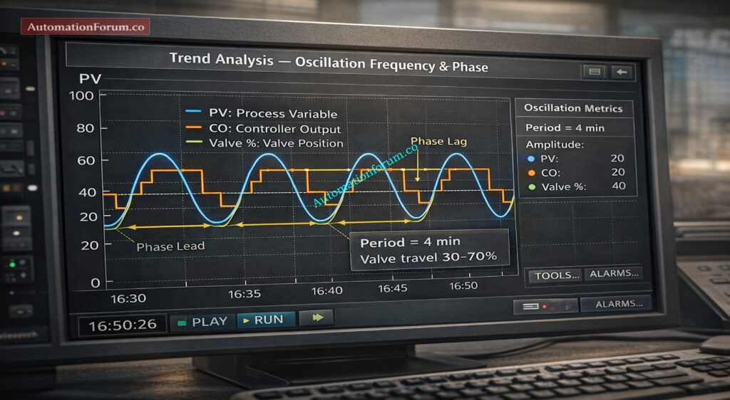
One frequent instability issue in industrial process control systems is control valve hunting. It describes a control valve’s prolonged cyclic movement combined with the process variable’s (PV) ongoing oscillation. The method overshoots and undershoots the desired value because the valve continually opens and closes in a rhythmic manner rather than gradually regulating to maintain setpoint.
How Control Valve Hunting Appears in DCS and PLC Trend Analysis
One frequent instability issue in industrial process control systems is control valve hunting. It describes a control valve’s prolonged cyclic movement combined with the process variable’s (PV) ongoing oscillation. The method overshoots and undershoots the desired value because the valve continually opens and closes in a rhythmic manner rather than gradually regulating to maintain setpoint.
Hunting is a sign of an improperly balanced feedback control loop from the standpoint of instrumentation and control. Poor PID tuning, high controller gain, integral windup, dead time, valve stiction, actuator problems, or signal noise could all be contributing factors. Control valve hunting must be recognized and addressed in order to preserve dependable plant operation and increase valve service life.
Root causes of valve oscillation: What are the main causes of control valve hunting?
Difference Between Normal Control Valve Modulation and Control Valve Hunting
Field engineers, loop tuning experts, and maintenance teams must be able to distinguish between healthy control action and unstable oscillation.
Characteristics of Stable Control Valve Modulation in Properly Tuned PID Loops
The valve exhibits predictable behavior in a control loop that is steady and appropriately adjusted:
- Small, smooth valve movement
- Quick settling after a disturbance
- Minimal overshoot
- Stable process variable
- Damped response over time
- Gradual correction toward setpoint
In this case, the process variable converges toward the setpoint without constant cycling while the controller output gradually changes. This indicates good loop tuning and proper interaction between controller, final control element, and process dynamics.
Size valves with confidence: Understanding Rangeability vs Turndown Ratio in Control Valve Sizing
Warning Signs and Oscillation Patterns of Control Valve Hunting in Industrial Automation Systems
On the other hand, there are obvious indications of instability in control valve hunting:
- Repetitive oscillation
- Noticeable overshoot and undershoot
- Regular periodic waveform on trend
- No natural damping
- Continuous valve travel swings
- Increased mechanical stress on actuator and trim
In the DCS or PLC trend, the oscillations usually happen at regular intervals and produce a sinusoidal or repeating pattern. If corrective action is not taken, the amplitude can stay the same or even rise.
Stop positioner-induced hunting: Control Valve Hunting due to Valve Positioner: Troubleshooting
Practical Example of Control Valve Hunting in a Heat Exchanger Temperature Control Loop
Oscillation Pattern, Valve Travel Fluctuation and Process Impact
Consider a heat exchanger temperature control loop in a process plant. If the outlet temperature oscillates every three minutes and the valve travel swings repeatedly between 40 percent and 65 percent, the loop is clearly unstable.
Operational and Maintenance Consequences of Sustained Valve Oscillation
Instead of stabilizing near the setpoint, the controller continuously overcorrects. In an established cycle, the temperature rises over the setpoint and subsequently falls below it. This state speeds up wear on the actuator diaphragm, stem, and control valve packing while also increasing energy consumption and decreasing heat transfer efficiency.
Persistent hunting can result in production losses, subpar products, and higher maintenance costs in major process sectors including petrochemical, oil and gas, and power generation facilities.
Metrics for reliable valve selection: Essential Control Valve Performance Parameters
Why Control Valve Hunting Is a Critical Problem in Process Industries
Impact on Process Stability, Product Quality and Energy Efficiency
Hunting for control valves is not only a tuning problem; it has a direct impact on:
- Process stability
- Equipment reliability
- Product quality
- Energy efficiency
- Maintenance frequency
- Overall plant safety
Early hunting detection through trend analysis and loop performance monitoring is crucial for instrumentation engineers and control system specialists. Oscillations can be avoided and steady performance restored with the aid of proper PID tuning, valve maintenance, and signal integrity checks.
Decode cascade loop diagrams: How to Read a DCS Cascade Control Loop Diagram: A Complete Guide with Example
How PID Controller Settings Cause Control Valve Hunting and Loop Instability
The most popular control algorithm in industrial process control systems is a PID (Proportional Integral Derivative) controller. Control valve hunting can be directly caused by aggressive tuning parameters or faulty configuration, even if it offers precise and reliable control when adjusted correctly.
Understanding Proportional, Integral and Derivative Action in Process Control
Three control terms are used by the PID controller to determine its output:
- Proportional reacts to present error
- Integral reacts to accumulated past error
- Derivative reacts to rate of change
The feedback control loop becomes unstable when these three terms are not appropriately balanced. This instability manifests as hunting, which is the recurrent movement of the control valve and prolonged oscillation of the process variable.
Inadequate PID tuning causes the control system to oscillate continuously, disrupts loop balance, and decreases stability margins.
Effect of Excessive Proportional Gain on Valve Oscillation
The controller’s response to the present error between the setpoint and process variable is determined by proportional gain.
When the proportionate gain is excessively high:
- Small error produces large output change
- Process overshoots setpoint
- Error reverses sign
- Controller reacts strongly again
- Continuous oscillation develops
Control valves exhibit fluctuating behavior as a result of this frequent error reversal. The valve keeps moving back and forth instead of settling at a stable position.
In processes with significant dead time, such as temperature loops in heat exchangers or long pipeline flow systems, high proportional gain drastically reduces phase margin. When phase margin decreases, loop stability is compromised, and sustained oscillation begins. Excessive gain makes the controller overly sensitive, turning minor disturbances into major control actions.
Integral Windup and Aggressive Integral Action as a Cause of Hunting
Integral action eliminates steady state error by accumulating error over time. This is necessary for precise control, but aggressive integral values can quickly make the loop unstable.
If integral time is too short:
- Integral accumulates too quickly
- Overshoot increases
- Integral windup occurs
- Oscillation continues without damping
Aggressive integral action is a big cause of PID tuning issues in sluggish processes like level control in tanks or big thermal systems. The controller keeps adding error even after the valve has reached its maximum, which means that corrective action takes longer and is too much.
The integral term can push the valve well beyond of the stable functioning range if it doesn’t have the right anti-windup protection, which can cause hunting to happen all the time.
Derivative Action and Noise Amplification in Industrial Signals
By predicting the future trend of error, derivative action creates damping. It responds to how quickly the process variable is changing, and when used effectively, it can make things more stable.
But derivative action also makes measurement noise worse.
If there is electrical noise or process problems in the transmitter signal:
- Derivative term creates output jitter
- Valve moves rapidly in small increments
- Small oscillations grow over time
- Mechanical wear increases
In real-world industrial settings, signals that are too loud are typical because of grounding problems, interference, or sensor wear. If you don’t filter properly, using derivative action can make valve oscillations worse instead of better.
You should only use derivative control when the signal quality is high and the signal is adequately filtered.
Prevent noise with correct earthing: Grounding and Bonding in Instrumentation and Control Systems
Wrong PID Mode Selection (Direct vs Reverse Acting) and Configuration Errors
If you set up the PID wrong, it might turn a stable loop into an unstable one right away.
Choosing the wrong control action is a common mistake:
- Direct acting instead of reverse acting
- Reverse acting instead of direct acting
This design mistake makes positive feedback instead of negative feedback, which makes things unstable right away and leads the control valve to hunt quickly.
Some such mistakes in the configuration are:
- Disabled anti-windup protection
- Incorrect output limits
- Improper cascade tuning
- Wrong sampling time
- Incorrect scaling of input signal
These misconfigurations directly cause oscillations in process control systems that are caused by PID controllers.
Loop Interaction and Cascade Control Instability
Control loops in factories don’t usually work on their own. It’s common for multiple loops to affect each other, and instability in one loop might spread to another.
For instance:
- Flow loop aggressively tuned
- Temperature loop depends on flow
- Flow oscillation transfers instability
- Temperature valve begins hunting
When diagnosing valve oscillation, you should always check loop interaction. Bad tuning of the cascade, response times that don’t match, or control mechanisms that don’t agree with each other can make the system more unstable.
Understanding process dynamics and ensuring proper coordination between loops is essential to prevent control valve hunting.
Advanced loop troubleshooting quiz: Advanced Control Valve Hunting Troubleshooting Quiz – Test Your Control Loop Expertise
Preventing PID-Induced Control Valve Hunting
Poorly tuned PID controllers frequently trigger control valve hunting by introducing excessive corrective action and reducing phase margin. To prevent oscillation, engineers should follow systematic PID tuning procedures, verify process dead time, and start with conservative gain settings.
Recommended practices include:
- Implementing anti-windup protection
- Applying derivative filtering
- Setting proper output limits
- Performing loop performance analysis
- Checking valve stiction and actuator response
- Verifying transmitter signal quality
Before making changes to live processes, simulation tools, loop tuning software, and performance monitoring systems can help find safe tuning settings.
In industrial automation systems, keeping the signal clean, making sure the valves are working properly, and using balanced PID tuning all make the loop more stable, decrease wear and tear on the machinery, improve the quality of the products, and make the whole process more efficient.
Know your DCS layers: Understanding the Difference Between DCS Components: ES, OS, and AS
Common Signs of Control Valve Hunting Due to Improper PID Tuning
You can find control valve hunting caused by bad PID tuning by carefully looking at trends and observing the field. Instrumentation engineers can stop catastrophic process instability and equipment damage by spotting these warning indicators early.
- Persistent sinusoidal trend pattern
- Valve position oscillates regularly
- Controller output oscillates at the same frequency
- Process variable does not settle at setpoint
- Frequent operator intervention required
- Audible actuator cycling or repetitive mechanical noise
Understanding trends is important. If the valve position always comes before the process variable, the controller is probably causing the oscillation instead than responding to a process disruption.
DCS trend monitoring and loop performance analysis can help find problems early, which makes control systems more reliable, cuts down on maintenance costs, and keeps industrial processes running smoothly.
DCS valve troubleshooting checklist: Checklist for Troubleshooting Control Valve in DCS Loop
Root Causes of PID Tuning Problems Leading to Valve Oscillation
Some problems in the field make control loops unstable and valves oscillate in industrial process control systems:
- Sensor lag
- Dead time in process
- Valve stiction
- Backlash in linkage
- Oversized control valve
- Noise in feedback signal
- Poor loop design
These things mess up the loop’s dynamics and make it less stable overall.
Process Dead Time and Phase Margin Reduction in Feedback Control Loops
In the control loop, dead time causes a lot of phase lag. More phase lag means less phase margin, and less phase margin means that oscillation will continue.
The PID controller keeps responding to old error data when the process reaction is delayed. Because of this delayed correction, there are recurrent overshoots and undershoots, which leads to constant valve hunting and unstable process variable behavior.
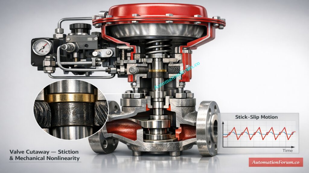
Valve Stiction, Backlash and Mechanical Nonlinearity Effects
One of the most common mechanical reasons for PID tuning issues is valve stiction.
- Valve sticks due to friction
- Controller output increases gradually
- Valve suddenly jumps to a new position
- Overshoot occurs
- Cycle repeats continuously
This stick-slip behavior makes the final control element respond in a way that isn’t linear. Mechanical nonlinearity makes bad PID tuning worse, making loops that are only slightly tuned unstable.
Taking care of the valves, making up for dead time, and tuning the loop in a methodical way all help to prevent valve oscillation and make the process control performance and operational efficiency much better.
Quick temperature loop checks: Troubleshooting of Temperature Controllers
Industrial Consequences of Continuous Valve Hunting
- Reduced valve life
- Seat and packing wear
- Actuator fatigue
- Increased compressed air usage
- Process instability
- Off specification production
- Energy loss
- Increased maintenance cost
In steam control systems, oscillating valves put more stress on turbines and make them less efficient.
Simplify multivariable control design: MIMO Decoupling Matrix Designer for Multivariable Process Control
Step-by-Step Troubleshooting Guide to Stop Control Valve Hunting
Step 1: Analyze High-Resolution Trend Data and Identify Oscillation Frequency
Get data with a lot of detail. Find the period and amplitude of the oscillation. Look at the phase relationship between the valve and the process variable..
Step 2: Verify PID Parameters and Compare with Commissioning Values
Write down the proportionate gain, the integral time, and the derivative time. Look at the original commissioning values.
Step 3: Inspect Control Valve Mechanical Condition and Check for Stiction
Do a stroke test. Look for reaction and stiction. Check how well the positioner works.

Step 4: Perform Bump Test to Measure Process Gain, Time Constant and Dead Time
Make a modest adjustment to the output. How to Measure:
- Process gain
- Time constant
- Dead time
For correct PID parameter modification, these values are needed.
Refer the below link for the What is Partial Stroke Test (PST)? A Complete Guide for Shutdown and Control Valves
Step 5: Apply Appropriate PID Tuning Method (Manual, IMC or Lambda Tuning)
Manual tuning might work for loops with low dead time.
IMC tuning is better for loops with a lot of dead time.
Lambda tuning makes the response smooth and easy to predict.
Step 6: Monitor Loop Stability Under Real Operating Disturbances
Check the loop throughout a number of operating cycles. Make sure that oscillation doesn’t come back when there is a disruption.
Compare PLC and PID roles: What is the difference between PLC and PID controller?
Practical PID Tuning Methods to Eliminate Control Valve Hunting
Manual PID Tuning Method for Low Dead Time Processes
- Start with a modest gain ratio
- Slowly get bigger
- Set the integral time close to the process time constant.
- Add a derivative only if you need to
Ziegler Nichols Tuning Method and Stability Margin Adjustment
- Find the final gain and time period.
- Figure out the parameters
- Lower gain for a safety margin
Lambda Tuning for Smooth and Predictable Closed Loop Response
- Choose the time you want for the closed loop
- Find the values of PID
- Gives a strong response
IMC Tuning for Dead Time Dominant Industrial Processes
- Model process that includes dead time
- Choose a filter factor
- Figure out the conservative controller parameters
When to Reduce Proportional Gain, Increase Integral Time or Disable Derivative Action
- If the frequency of oscillation is high
- If overshoot is too high
When to Increase Integral Time
- If you see an integral wind up
- If the oscillation gets bigger after a disruption
Spreadsheet PID testing tool: Excel based PID Loop Simulator
How to Prevent Control Valve Hunting in New Installations and Commissioning
- Proper valve sizing
- Correct actuator selection
- High resolution positioner
- Minimal mechanical backlash
- Accurate transmitter placement
- Signal filtering
- Periodic loop performance audit
Preventive design reduces future PID tuning problems.
See PID on motors: PID controller tuning – With motor and gear example
Real World Case Study of Control Valve Hunting Due to Improper PID Tuning in a Petrochemical Reactor
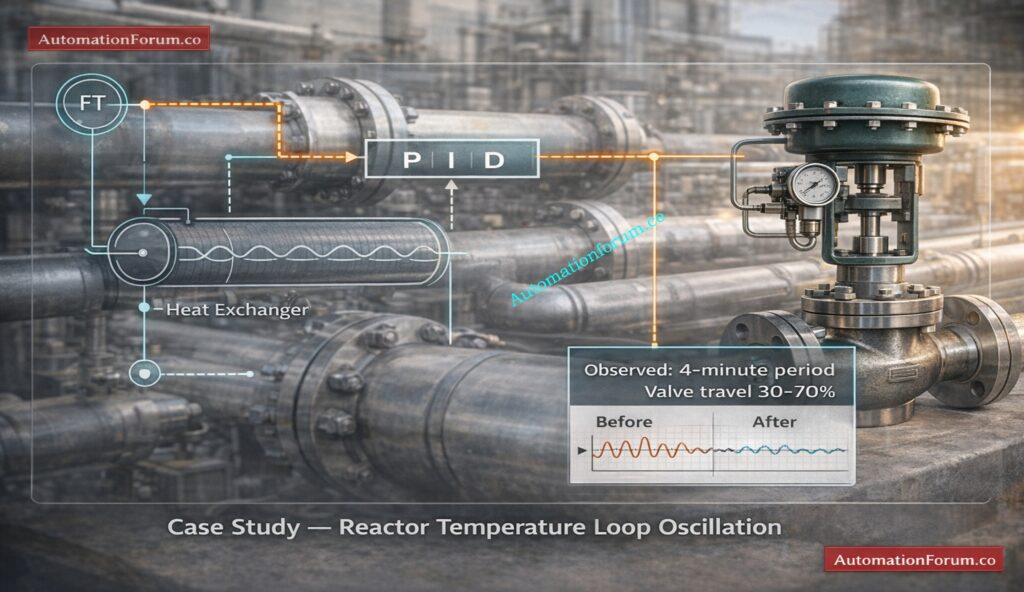
After the feed composition changed, the temperature control loop in a petrochemical reactor started to oscillate. The disturbance altered process dynamics, but the existing PID tuning parameters were not adjusted accordingly. As a result, the control valve started hunting, causing instability and product quality variation.
Observed Oscillation Behavior and Trend Analysis
- Four-minute oscillation cycle
- Valve movement from 30 percent to 70 percent
- Product quality deviation
- Increased operator monitoring
The DCS trend showed a clear sinusoidal waveform, confirming sustained oscillation rather than random disturbance.
Root Cause Diagnosis Including Dead Time and Aggressive PID Parameters
A detailed investigation of the loop showed:
- Dead time: 40 seconds
- Time constant: 150 seconds
- High proportional gain
- Short integral time
- Minor valve stiction
The large proportional gain and short integral time made the phase margin much smaller. Dead time made instability much worse, and slight valve stiction made oscillatory behavior even worse.
Corrective Actions Applied to Restore Loop Stability
A methodical way to fix problems was used:
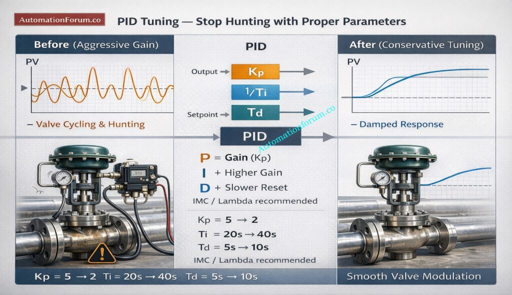
- Reduce proportional gain by 40 percent
- Increase integral time
- Disable derivative action
- Service and lubricate control valve
Measured Improvement in Process Stability and Product Quality
- Oscillation reduced by 90 percent
- Stable reactor temperature
- Improved product quality
- Reduced maintenance frequency
Refer the below link for the Best PID Controller Tuning Simulation Tool for Engineers
Frequently Asked Questions About Control Valve Hunting and PID Tuning Problems
What is the cause of control valve hunting
Improper PID tuning, like high proportional gain or aggressive integral action, is what mostly causes control valve hunting. It can also result from process dead time, valve stiction, signal noise, or loop interaction that makes the controller overcorrect continuously.
What Is the Most Common PID Parameter That Causes Control Valve Hunting
Excessive proportional gain is the most common PID parameter that causes hunting. When gain is too high the controller reacts too aggressively to small errors and creates sustained oscillations in the valve and process variable.
What is hunting in controls
Hunting in controls is a condition where the control system continuously oscillates around the setpoint instead of stabilizing. The process variable repeatedly overshoots and undershoots, forming a regular waveform in trend data.
How Can I Differentiate Between Valve Stiction and PID Tuning Problems
When a valve sticks, the controller output normally has a sawtooth pattern, and the valve position suddenly jumps. PID tuning problems usually show smooth sinusoidal oscillations when the process variable follows the controller output.
Should Derivative Action Be Used to Stop Valve Hunting
Derivative action can help add damping and improve stability in some loops. However it can amplify signal noise, so it should only be used when measurement signals are clean and properly filtered.
Master PID adjustments fast: PID controller tuning
How to Achieve Long-Term Loop Stability and Eliminate Control Valve Hunting in Industrial Automation Systems
Control valve hunting produced by a PID controller is basically a problem with the stability of the control loop. This might happen because the PID tuning is wrong, there is too much dead time, there are mechanical flaws, or the loops interact with each other. A organized troubleshooting procedure that includes trend analysis, bump testing, mechanical inspection, and improved PID tuning makes sure that processes stay stable over time, use less energy, and work reliably in industrial automation.
Proper PID parameter adjustment combined with correct valve sizing and preventive maintenance ensures stable process control, longer equipment life, improved product quality, and enhanced plant reliability.
Post-service sealing diagnostics: How to Troubleshoot a Control Valve Passing Problem after Overhauling: Complete Root Cause Analysis