- What is a Process Value Cross Check in Instrumentation?
- Why Process Value Cross Check is Important for Safety Quality and Compliance
- Process Value Cross Check Methods – Gauge Comparison Portable Calibrator and Manual Calculation
- Local Gauge and Sight Glass Verification Method
- Temporary Reference Instrument Verification Using Portable Calibrator
- Manual Calculation Method for Flow and Level Cross Check
- Step by Step Process Value Cross Check Procedure – Field Checklist for Technicians
- Field Log Template for Process Value Cross Check Documentation
- How to Interpret Cross Check Results – Offset Drift and Scaling Errors
- Decision Rules for Field Troubleshooting During Process Value Cross Check
- Common Root Causes Identified During Process Value Cross Check
- Best Practices, Frequency and Documentation for Audits
- Case Study – Flow Transmitter Validation Using Manual Calculation and Pitot Measurement
- Training and Standard Operating Procedure for Process Value Cross Check
- Digital Documentation and Mobile Data Capture for Process Value Cross Check
- Process Value Cross Check – Field Validation and Transmitter Verification Checklist
- Build a Reliable Process Value Cross Check Culture
What is a Process Value Cross Check in Instrumentation?
Definition and Purpose of Process Value Cross Check
A Process Value Cross Check is a useful way to check if a transmitter is showing the right process value while it is running.
It means checking the transmitter reading against a separate reference, like:
- A local gauge or sight glass
- A temporary reference instrument or portable calibrator
- A manual calculation that uses engineering formulas
The goal is to immediately find out if the instrument is correct or if the problem is caused by drift, a configuration error, a mechanical blockage, electrical noise, or changing process conditions.
A cross check checks performance directly in the running process, which is different from full calibration.
Why Transmitter Reading Verification is Critical in Process Industries
In process industries, transmitter readings control safety systems, product quality, and operational efficiency. An incorrect reading can cause:
- False trips and shutdowns
- Off specification product
- Incorrect control actions
- Safety risks
Even slight mistakes in measurements can have big effects on finances and operations.
Routine Process Value Cross Checks assist find offsets, spot drift early, avoid downtime, and make preventive maintenance plans stronger.
Fix PLC Analog Output Failures Before Startup: Troubleshooting Analog Output Signals in PLC Loops – Advanced Scenario-Based Quiz for Process Industries
Why Process Value Cross Check is Important for Safety Quality and Compliance
Preventing False Trips and Unnecessary Shutdowns
A Process value cross check is not a paperwork exercise it is a frontline defence for safety product quality and regulatory compliance. Field teams that routinely cross check instrument readings identify wrong range incorrect density settings and scaling errors before they cause false trips overfill or off specification product.
Avoiding Off Specification Product and Process Loss
Cross checks reduce unplanned downtime by catching problems early. For example a level transmitter reporting full while a sight glass shows half full may trigger unnecessary shutdowns or emergency valve action. Conversely under reporting flow can lead to product shortfalls that damage customer relationships.
Reducing Maintenance Cost Through Early Drift Detection
Key reasons to cross check include safety quality cost avoidance and preventive maintenance value. A short list follows
- Safety detect runaway conditions or stuck valves before escalation
- Quality and compliance demonstrate measurement verification for audits
- Cost avoidance prevent false trips unnecessary purges and scrapped batches
- Preventive maintenance identify drift and schedule calibration or replacement
Cross checks are particularly useful where fluid density changes with temperature or composition and where instrument range was adjusted during maintenance. A simple comparison between a transmitter and a local gauge often reveals configuration errors that mimic sensor failure.
Stop Control Valve Hunting Before It Destroys Your Process: Control Valve Hunting Troubleshooting – Advanced MCQ Quiz
Process Value Cross Check Methods – Gauge Comparison Portable Calibrator and Manual Calculation
Choose comparison methods that expose different failure modes. Use a local gauge or sight glass for quick visual confirmation. Use a temporary reference instrument such as a portable calibrator for traceable verification. Use a manual calculation as an independent engineering check when other instruments are not available.
Master PLC Permissive Logic or Expect Costly Trips: PLC Permissive Logic Troubleshooting Procedure for Instrumentation Engineers
Local Gauge and Sight Glass Verification Method
When to Use Local Gauge for Pressure Level and Temperature Cross Check
Use local gauges and sight glasses for quick field checks of pressure level and temperature. They are simple to read and require no electronics.
Accuracy Limitations of Mechanical Gauges
Mechanical gauges and sight glasses are robust but coarse in accuracy typically within one to five percent. They are prone to parallax and blocked impulse tubing but are practical for rapid checks.
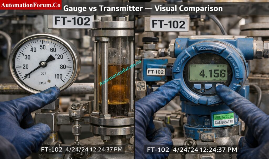
Practical Field Example of Gauge vs Transmitter Comparison
A differential pressure transmitter for level cross checked against a sight glass on the same vessel may show disagreement. If the sight glass shows half full but the transmitter shows full investigate impulse tubing and density compensation in the transmitter.
Control Valve Not Responding Find the Real Field Cause: Field Troubleshooting Guide: Control Valve Not Responding in Process Area
Temporary Reference Instrument Verification Using Portable Calibrator
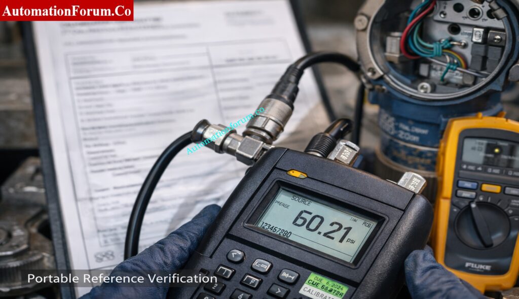
Why Portable Calibrators Provide Traceable Verification
A portable instrument provides a calibrated reference for verification. Common tools include pressure calibrators clamp on ultrasonic meters pitot tubes and portable temperature calibrators. Use these when precise comparison is needed.
Accuracy Expectations and Calibration Certificate Requirements
Portable calibrators often have traceable accuracy better than one percent. Correct connection and stable process conditions are required. Check the calibration certificate before use.
Field Example of Transmitter Output Validation Using Reference Instrument
A portable pressure calibrator applied to the impulse port confirms or rejects the transmitter output. If the calibrated device agrees with the local gauge but not with the transmitter suspect configuration or transmitter failure.
Calibrate Control Valves the Right Way Not by Guesswork: Control Valve Calibration Procedures
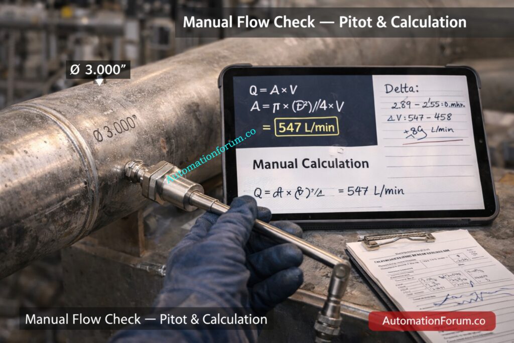
Manual Calculation Method for Flow and Level Cross Check
Purpose and when to use
Manual calculations use fundamental physical relationships to provide an independent check. Use area times velocity for flow checks and hydrostatic head for level checks when other references are not present.
Accuracy and limitations
The accuracy depends on input data quality such as pipe internal diameter velocity measurement and fluid density. Treat manual calculation as a sanity check and record assumptions.
Example
Calculate flow in a three inch pipe using measured velocity and pipe internal diameter then compare with the flow transmitter reading to identify possible span issues or two phase flow.
Motorized Control Valve Calibration Done Wrong Costs Production: Calibration Procedure for Motorized Control Valve
Step by Step Process Value Cross Check Procedure – Field Checklist for Technicians
Follow a methodical sequence. Start with safety and pre checks then record readings and observations. The checklist below is designed to be copied into a field log.
Pre Check Safety and Documentation Requirements
- Record tag and loop identifier instrument model and last calibration date
- Confirm process conditions including temperature pressure and flow state steady or transient
- Follow isolation and lock out procedures and notify operations
- Complete safety permit and ensure personal protective equipment is in place
- Verify that the temporary reference instrument has a current calibration certificate and sufficient battery
Measurement Stabilization and Repeatability Check
- Allow the process to stabilise if safe to do so
- Record three readings for each source transmitter local gauge and temporary reference spacing readings to assess repeatability
- Perform a manual calculation where applicable and note formula and assumptions used
- Record ambient and installation observations such as impulse tubing wetting presence of air in line valve positions and any mechanical vibration
- Mark the readings with timestamp and operator name for traceability
Eliminate 4 to 20 mA Loop Errors Before Commissioning: Live Signal Verification 4 to 20 mA Loop Standard Operating Procedure (SOP)
Field Log Template for Process Value Cross Check Documentation
| Timestamp | Tag | Transmitter value | Local gauge | Temporary reference | Manual calculation | Delta | Condition notes | Action |
| 10 12 | PT 101 | 3.45 bar | 3.40 bar | 3.42 bar | n a | 0.05 bar | Impulse tubing wet | Monitor |
| 10 16 | FT 205 | 547 litres per minute | n a | 552 litres per minute | 547 litres per minute | 5 litres per minute | Pipe vibration | Check flowmeter span |
How to Record Delta and Tolerance
Set site specific tolerance based on criticality. Typical examples are one to two percent for critical control loops three to five percent for monitoring loops and two to five percent for mechanical gauges. Convert percentage tolerances to engineering units at normal operating points and record them.
IEC 61511 Bypass Mistakes That Can Shut Down Your Plant: IEC 61511 Safety Bypass And Override in Instrumentation and Control System Maintenance
How to Interpret Cross Check Results – Offset Drift and Scaling Errors
- Patterns in the data reveal the likely cause. A steady offset where the difference is constant across conditions suggests calibration or configuration error.
- Drift over time suggests sensor ageing moisture ingress or progressive electronics fault. Random scatter points to mechanical or electrical noise such as blocked impulse tubing loose connectors or power supply instability.
- If the offset changes with temperature or composition suspect density compensation or range mismatch. For example a differential pressure transmitter used for level measurement will respond to fluid density changes. If the difference grows with signal amplitude investigate transmitter linearity and span.
PLC Panel Inspection Failures You Should Never Ignore: Running Inspection Checklist of PLC Components in Control Panels
Decision Rules for Field Troubleshooting During Process Value Cross Check
- Constant offset then check transmitter zero span and engineering units
- Offset varies with temperature then verify density compensation and temperature correction values
- Large random scatter then inspect impulse tubing connectors and power wiring and earthing
Partial Stroke Testing Mistakes That Damage Shutdown Valves: What is Partial Stroke Test (PST)? A Complete Guide for Shutdown and Control Valves
Common Root Causes Identified During Process Value Cross Check
Here are common causes with immediate corrective steps to try in the field.
Mechanical Causes Such as Blocked Impulse Tubing
- Blocked impulse tubing or clogged tap
Action isolate depressurise and clean the tubing and fit a blow down valve with filter - Partially closed valve in the impulse line
Action verify valve position open fully and retest
Electrical Causes Including Ground Loop and Power Ripple
- Poor earthing or ground loop
Action inspect earthing points separate signal wiring and measure supply ripple - Loose or corroded connectors
Action tighten clean and reseal connectors
Configuration Errors Such as Wrong Range or Engineering Units
- Incorrect range or units
Action verify tag sheet update transmitter configuration and record change - Wrong fluid density or compensation value
Action update density value in transmitter and verify behaviour
Process Related Issues Including Two Phase Flow
- Air entrainment or layering
Action inspect vessel perform purge or change sampling point - Two phase flow in a single phase sensor line
Action fit a phase separator or relocate sensor
Calibration Errors That Fail Audits and Shutdown Projects: Calibration Guidelines
Human Errors Such as Wrong Scale Reading
- Wrong instrument or scale read
- Action label instruments clearly and train staff on correct reading practice
After corrective steps re run the cross check and log outcomes to build an audit trail.
Cold vs Hot Loop Checking Stop Confusing Them: Cold and Hot Loop Checking in Automation: Key Differences and Step-by-Step Procedures
Best Practices, Frequency and Documentation for Audits
- Define frequency by loop criticality. Critical safety loops may need daily to weekly checks. Important process control loops are often checked weekly to monthly.
- Low risk monitoring loops can be checked quarterly. Use failure history to adjust cadence and focus resources where they reduce risk most.
- Use data historians and statistical analysis to detect slow drift. Set up alarms for persistent offset and trend anomalies so maintenance resources are deployed where they matter most.
- For audits keep a linked record showing who performed the check what temporary reference instrument was used and attach calibration certificate evidence. Use digital forms to reduce transcription mistakes and preserve timestamps and operator identity.
- Include cross check status in shift handovers and maintenance work packs. Use standard forms to ensure consistent recording and escalation paths.
Pressure Transmitter Loop Errors That Cause False Trips: Method Statement for Loop Checking of Pressure Transmitter Loop
Case Study – Flow Transmitter Validation Using Manual Calculation and Pitot Measurement
Field Scenario Description
- Scenario FT 205 a differential pressure based flow transmitter reports five hundred and sixty litres per minute.
- Operations doubt the reading. A pitot temporary reference monitors the speed of a fluid in a three-inch pipe at two meters per second.
- To find volumetric flow, multiply the area by the velocity and compare the results.
Step by Step Flow Calculation
- The pipe’s diameter is three inches, which is seventy-six point two millimeters or zero point zero seven six two meters. To find Area A, multiply pi by the diameter squared and then divide by four.
- The square of the diameter is zero point zero seven six two times zero point zero seven six two, which is zero point zero zero five eight zero six four four.
- To get zero point zero one eight two four one, multiply by pi. Then, to get zero point zero zero four five six zero three seven square metres, divide by four.
- To get zero point zero zero nine one two zero seven four cubic metres per second, multiply the area by the speed of two metres per second. Convert to litres per minute multiply by one thousand then by sixty to obtain approximately five hundred and forty seven litres per minute.
Refer the below link for the Free Instruments Calibration Procedures: 60+ Step-by-Step Methods for Pressure, Temperature, Flow & Level
Delta Analysis and Acceptance Decision
- The calculated flow of approximately five hundred and forty seven litres per minute compared with the transmitter five hundred and sixty litres per minute yields a delta of thirteen litres per minute or two point four percent.
Recommended Corrective Actions for Marginal Results
- For a critical loop with a tolerance of one to two percent this is marginal.
- Actions include repeating the measurements confirming pitot calibration checking pipe internal diameter and verifying there is no two phase flow present.
- Log results attach calibration certificate images and schedule corrective action if required.
MOV Loop Checking Errors That Delay Commissioning: How to do loop checking of Motor operated valve?
Training and Standard Operating Procedure for Process Value Cross Check
- Ensure technicians receive hands on training and shadowing.
- Keep a clear standard operating procedure for cross-checks that includes a step-by-step list of tasks, a way to record measurements, and rules for how to handle problems.
- Use what you learned from cross checks to change your procedures and tolerances.
- Add the status of the cross check to the daily handover notes, and make sure that any remedial action has a maintenance ticket reference so that it can be checked.
Boiler DP Transmitter Commissioning Mistakes to Avoid: Commissioning Procedure for Differential Pressure Transmitters in Pressurized Boiler Steam Drums
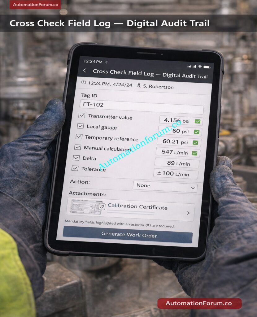
Digital Documentation and Mobile Data Capture for Process Value Cross Check
Benefits of Structured Digital Forms
- Using mobile forms to collect data cuts down on transcribing mistakes and makes it easier to follow the process value cross-check.
- Technicians can now enter values immediately into a structured digital form on a tablet or industrial mobile device instead of writing them down in a notebook and then entering them into a maintenance system.
Mandatory Fields for Traceability and Compliance
This method makes sure that:
- Recording timestamps automatically
- Identifying technicians through login
- Required to fill out important fields
- Directly attaching photos of calibration certificates
- Sharing right away with supervisors or reliability teams
Refer the below link for the 50+ Instrumentation and Control System Troubleshooting Procedure
Attaching Calibration Certificate Evidence
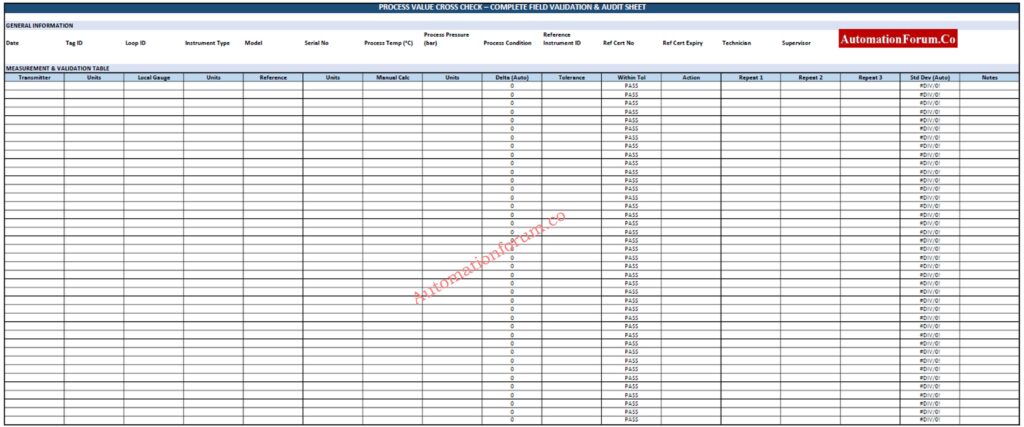
A well designed digital form should include the following fields:
- Tag ID
- Date and time
- Operator name
- Process temperature
- Process pressure
- Transmitter reading with units
- Local gauge reading with units
- Temporary reference reading with units
- Manual calculation result
- Calculated delta
- Allowed tolerance
- Within tolerance Yes or No
- Action taken
- Calibration certificate image attachment
Automatic Work Order Generation When Tolerance Is Exceeded
- Including a picture of the temporary reference instrument and its calibration certificate makes it easier to track audits and shows that the cross-check was done with a properly calibrated equipment.
- If the delta goes over the limit, the form can automatically make a work order when it is linked to a maintenance system. Stored recordings help find problems with drift or mechanics that happen over and over again.
Control Valve Passing After Overhaul Find the Root Cause: How to Troubleshoot a Control Valve Passing Problem after Overhauling: Complete Root Cause Analysis
Process Value Cross Check – Field Validation and Transmitter Verification Checklist
A Process Value Cross Check is a useful way to make sure that a transmitter accurately shows how the process is doing right now. It checks the accuracy of the measurement by comparing the transmitter reading to a nearby gauge, a portable calibrated equipment, or a manual calculation.
With automatic delta calculation, tolerance evaluation, and action logging, this checklist gives you an organized, audit-ready way to do things. It helps find drift, configuration mistakes, and mechanical or electrical problems early, which helps keep people safe, improve product quality, and keep up with maintenance schedules.
Download : Process_Value_Cross_Check_ENTERPRISE
4 to 20 mA Loop Troubleshooting Without Trial and Error: 4-20 mA Loop Troubleshooting with Loop Calibrators : A Practical Guide
Build a Reliable Process Value Cross Check Culture
Loop Check vs Functional Test Know the Critical Difference: Loop Check vs Functional Test in Instrumentation Commissioning