- What is a Loop Calibrator
- Why 4-20 mA Loops are Critical in Process Control
- Mode 1 – Measure Mode (Verifying Loop Current)
- Mode 2 – Source Mode (Testing Controllers and Valves)
- Mode 3: Simulate Mode – Testing Loop Infrastructure
- Choosing the Right Mode – Quick Decision Guide
- Common problems in 4-20 mA loops
- FAQs on 4-20 mA Loop Troubleshooting with Loop Calibrators
What is a Loop Calibrator
The loop calibrator is an important equipment for an industrial process control trained instrument technician to use when fixing 4-20 mA current loop circuits. These handheld instruments can measure current, generate current signals, and act like field transmitters. To fix problems quickly and effectively, you need to know how to use their three different modes: Measure, Source, and Simulate.
In the following article, we’re going to utilize a real-life example: A pressure transmitter that has been set up to read between 0 and 750 inches of water column and sends 4-20 mA to a controller that shows 0 to 750.
4-20 mA Transmitter Output Calculator for Process Values: 4 to 20 mA Transmitter Output Process Value Calculator
Why 4-20 mA Loops are Critical in Process Control
In process control, the 4-20 mA current loop is the common way to send analog signals. It is preferred because:
- Noise resistant: current is unaffected by long cable runs or electrical interference.
- Two-wire simplicity: same pair of wires powers the transmitter and carries the signal.
- Live zero (4 mA start): distinguishes true zero from loop faults (0 mA = failure).
- Universal compatibility: supported by all transmitters, controllers, and PLC/DCS systems.
- Linear and reliable: easy to scale (e.g., 12 mA = 50% of range).
Example: A pressure transmitter scaled 0-750 in. W.C. outputs 4 mA at 0 and 20 mA at 750. At 12 mA, the controller reads 375 simple and accurate.
Mode 1 – Measure Mode (Verifying Loop Current)
When to use Measure Mode
Use measure mode when you need to verify what current is actually flowing in an operating loop when troubleshooting unexpected controller readings, suspected wiring problems, or performing routine calibration checks.
Circuit Configuration in Image – Loop Calibrator Acting as an Electrical Load (Measure Mode)
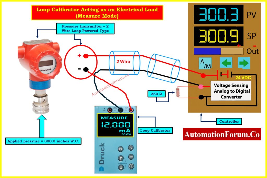
Loop Calibrator acting as an Electrical Load (Measure Mode) Image shows the calibrator in Measure Mode, acting as a passive device. Key elements:
- The Pressure Transmitter (bottom left): Experiencing 300.3 inches W.C. pressure
- Connection Point: The calibrator connects in series at the transmitter’s negative terminal (shown in red circle)
- Calibrator Display: Shows “MEASURE 12.000 mA” (50.0%)
- Field Wiring: Two-wire cable carries signal to the controller
- Controller’s 250Ω Resistor: Converts current to voltage for the analog-to-digital converter
- Controller Display: Shows PV = 300.3, confirming correct signal interpretation
- Power Source: The controller’s 24 VDC supply provides all loop power
Critical Connection Details
Polarity matters: Connect the red (positive) lead to the more positive side and black (negative) lead to the more negative side. The calibrator measures current without providing power it’s like an ammeter inserted in series.
For faster testing, if a test diode is installed in the loop, connect the calibrator in parallel with the diode instead of breaking the wire.
Interpreting Results and Troubleshooting Tips
With 300.3 inches applied (40.4% of 750 range), we had expect approximately 10.5 mA. The measured 12.0 mA suggests possible transmitter miscalibration or sensor drift. Since the controller correctly displays 300.3 for 12 mA, the problem lies in the transmitter, not the controller or wiring.
Refer the below link for Understanding the Difference Between Live Zero and Dead Zero in 4 to 20 mA signal
Mode 2 – Source Mode (Testing Controllers and Valves)
When to use Source Mode
Source mode tests receiving instruments independently perfect for commissioning controllers, testing control valves, measuring valve friction, and verifying alarm setpoints.
Testing a Controller Input
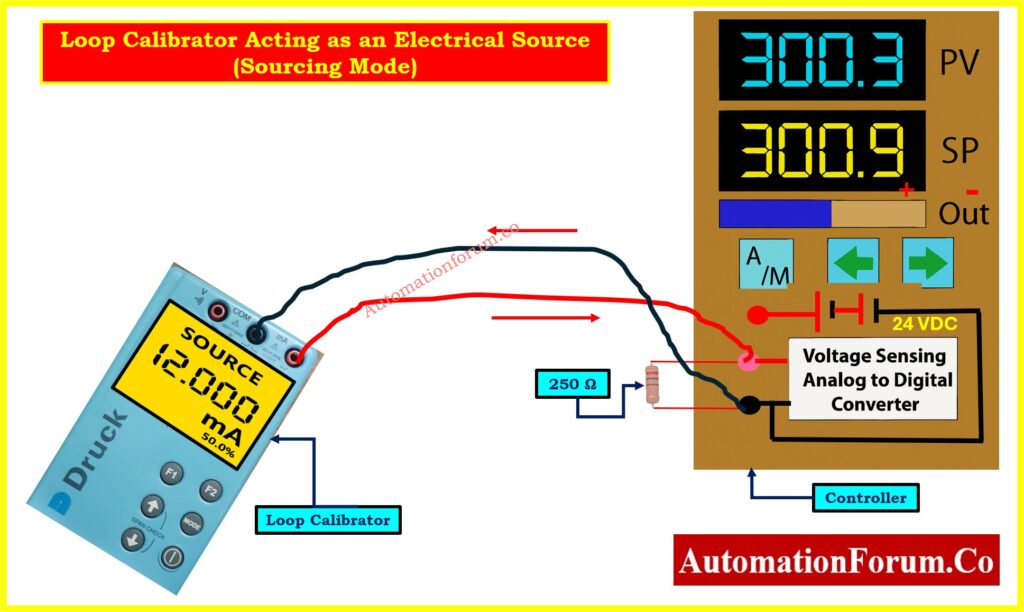
Loop Calibrator Acting as an Electrical Source (Sourcing Mode) Image shows the calibrator in Source Mode with the transmitter completely removed:
- Calibrator Display: Shows “SOURCE 12.000 mA” (50.0%)
- Power Source: The calibrator’s internal battery provides both signal regulation and electrical power
- Controller’s Supply Unused: The 24 VDC supply is present but not providing loop power
- Current Path: Flows from calibrator through the 250Ω resistor and back
- Controller Display: Shows PV = 300.3, confirming correct interpretation
This isolates the controller for independent testing. If the display is wrong, the problem is definitely in the controller, not the transmitter or field wiring.
Calculate Transmitter Span, LRV & URV from 4-20 mA: Transmitter Calibration Span, LRV and URV Value Calculator from Measured 4 to 20 mA
Testing a Control Valve
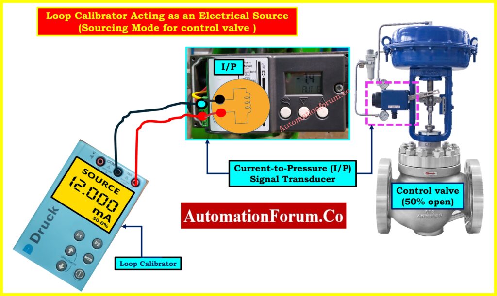
Loop Calibrator Acting as an Electrical Source for Control Valve demonstrates the most common use of source mode: valve testing. The setup shows:
- Control Valve Assembly (right): Includes pneumatic actuator (blue cylinder), positioner (magenta dashed box), and valve body, shown at 50% open
- Calibrator Connection: Displays “SOURCE 12.000 mA” and connects directly to the I/P terminals
- Signal Flow: Calibrator to I/P Transducer to Pneumatic Output (3–15 PSI) to Actuator to Valve Operation movement
Refer the below link for Cold and Hot Loop Checking in Automation: Key Differences and Step-by-Step Procedures
Field Testing Advantage
The technician can stand at the valve with the calibrator, making immediate adjustments while observing valve response far superior to coordinating with a control room operator via radio.
Diagnosing Valve Friction (Step Response)
Source mode is great for finding mechanical problems:
- Set the calibrator to 12.000 mA and check that the valve advances to 50%.
- Take significant action (±4 mA) The healthy valve should respond.
- Try progressively smaller steps: 0.8 mA, 0.4 mA, 0.2 mA, 0.1 mA
- Results:
- Low friction: reacts to steps of 0.2 mA (1.25%)
- Moderate friction: Needs steps of 0.4 to 0.8 mA (2.5 to 5%)
- High friction: Needs steps of 1–2 mA or more (needs maintenance)
Safely Measure mA Current in Instrument Loop: How to Safely Check the mA Current of an Instrument Loop Using a Multimeter
Positioners vs I/P Transducers
The picture shows a positioner, not just a regular I/P transducer. Positioners have sensors that give input on the position and adjust the pressure constantly to make sure the valve gets to the right place, taking into account friction and process forces. This gives you a considerably higher level of precision (usually ±0.5% or better).
Why 4-20 mA Current Signal Beats Voltage: Why 4-20 mA Current Signal is Preferred Over Voltage Signal in Instrumentation?
Mode 3: Simulate Mode – Testing Loop Infrastructure
When to use Simulate Mode
Simulate mode tests the whole system by acting like a true two-wire transmitter. This is important for setting up new installations, checking them before they start up, and making sure that power sources work when they are under load.
Critical Difference: Simulate vs. Source
Source Mode: The calibrator gives you both current regulation and power from its own battery. Tests signal interpretation but NOT the loop’s power supply.
Simulate Mode: Calibrator regulates current but relies on the loop’s 24 VDC supply for power. Tests the COMPLETE system: power supply, wiring, and input circuit.
4-20 mA vs 0-20 mA Explained for Instrumentation: Why not use 0-20mA & 0-15psi instead of 4-20mA & 3-15psi?
Circuit Setup in Simulation Mode
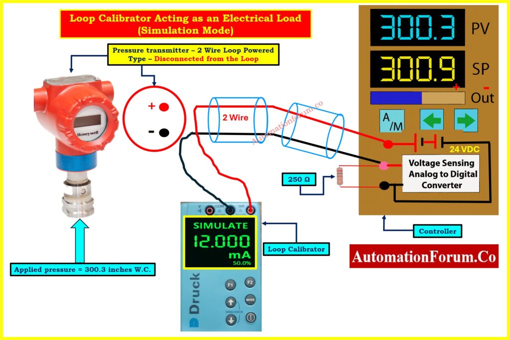
Loop Calibrator Acting as an Electrical Load (Simulation Mode) Image shows simulate mode during commissioning:
- Transmitter Status: Physically present but labeled “Disconnected from the Loop”
- Calibrator Display: Shows “SIMULATE 12.000 mA” (50.0%) in green text
- Power Flow: The controller’s 24 VDC supply now provides loop power
- Current Path: From +24V → through calibrator (which regulates to 12 mA) → through 250Ω resistor → back to supply
- Controller Display: Shows PV = 300.3
What Simulate Mode Reveals
Testing under realistic load conditions reveals:
- Power supply adequacy: Can it provide sufficient current and voltage?
- Voltage drop: When you run a long wire, the voltage at the calibrator terminals goes down.
- Wiring problems: Unexpected resistance shows that the connections are bad.
- Complete loop operation: Problems with ground loops, interference, and shielding become clear
Five-Point Commissioning Check
Two technicians are usually needed in the industry:
Field Technician (with calibrator):
- It can simulate 4 mA (0%), 8 mA (25%), 12 mA (50%), 16 mA (75%), and 20 mA (100%).
- Records voltage at the calibrator terminals
- Looks for problems with the wiring
Control Room Technician (at controller):
- Checks to see if the display is correct: 0, 187.5, 375.0, 562.5, 750.0
- Tests the alarm to see if it goes off at the right times
- Keeps track of all readings
Troubleshooting Examples
Controller shows 325 instead of 375 at 12 mA: The problem is with the controller scaling, not the loop.
Only 18V at calibrator when simulating 20 mA: Too much voltage drop check the size of the wires and the connections.
Cannot simulate 20 mA: The supply voltage is too low for the entire loop resistance.
Role of 250-Ohm Resistor in HART Communication: Why is a 250-Ohm Resistor Important for HART Communication?
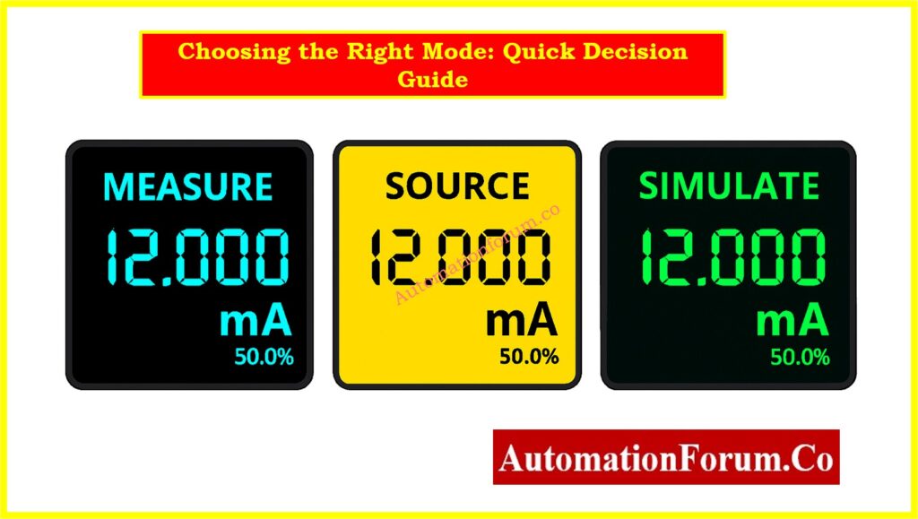
Choosing the Right Mode – Quick Decision Guide
Use Measure Mode when:
- Verifying actual current in operating loop
- Troubleshooting unexpected controller readings
- Checking transmitter output against known conditions
- Diagnosing wiring problems
Use Source Mode when:
- Testing controller independently of transmitter
- Calibrating or stroke-testing control valves
- Diagnosing valve friction
- Verifying alarm setpoints
- Need maximum precision for calibration
Use Simulate Mode when:
- Commissioning new installations
- Testing complete signal path including power supply
- Verifying wiring integrity under load
- Pre-startup system checkout
- Want to test exactly as a real transmitter operates
Effective troubleshooting isn’t just having a loop calibrator it’s knowing which mode to use. Measure mode tells you what’s happening now. Source mode lets you control exactly what signal a device receives. Simulate mode tests your infrastructure as if a real transmitter were connected. Master these three modes, and you’ll diagnose most loop problems in minutes rather than hours.
Simulate 4-20 mA Signal Using Loop Calibrator: How to simulate 4-20ma signal with Loop Calibrator ?
Common problems in 4-20 mA loops
Here are several problems that often come up with 4-20 mA loops:
| Problem | Symptoms | Likely Causes / Fixes |
| 0 mA / No signal | Loop reads nothing | Open circuit, damaged wire, blown fuse, dead power supply, or transmitter failure |
| Stuck at 4 mA or 20 mA | Cannot change signal | Sensor saturation, shorted wiring, calibration limit, wiring error. |
| Erratic / noisy readings | Unstable displayed value | Electrical noise, ground loops, moisture in cables, shielding issues. |
| Offset / scaling error | System reading always some offset | Improper scaling in controller, transmitter drift, leakage current or resistance in wiring. |
| Voltage drop / insufficient loop power | Calibrator cannot drive full current or low loop voltage | Cable length too long, high resistance wiring, weak power supply. |
| Leakage / grounding faults | Unexpected current paths, mismatch between measured and read values | Moisture ingress in junction boxes, improper shield grounding (both ends), insulation breakdown. |
Using a thorough troubleshoot technique (measure, isolate, simulate/source) helps find the problem.
Step-by-Step 4-20 mA Loop Troubleshooting Guide: How to do troubleshooting of a 4-20mA loop?
FAQs on 4-20 mA Loop Troubleshooting with Loop Calibrators
What is the difference between simulate and source mode in a loop calibrator?
In source mode, the loop gets both current and power. In simulation mode, the loop’s external 24 VDC supply controls the current, making it operate like a two-wire transmitter.
Loop Check vs Functional Test Explained for Commissioning: Loop Check vs Functional Test in Instrumentation Commissioning
How do you troubleshoot a 4-20 mA loop with a loop calibrator?
Check the wiring and power, then measure the loop current. Use simulate mode to emulate the transmitter and source mode to test controllers or valves until you find the problem.
Can a loop calibrator test control valves directly?
Yes, in source mode it can send a 4-20 mA signal to the valve’s I/P transducer, letting you check valve movement, friction, and positioner performance.
What are common problems in 4-20 mA loops?
Common problems are open circuits, no loop power, scaling mistakes, loud signals, voltage decreases over long runs, or grounding and shielding problems.
What is the difference between source and simulate mA?
Source mA actively drives current and powers the loop; mimic mA regulates current but relies on the loop’s existing supply voltage.