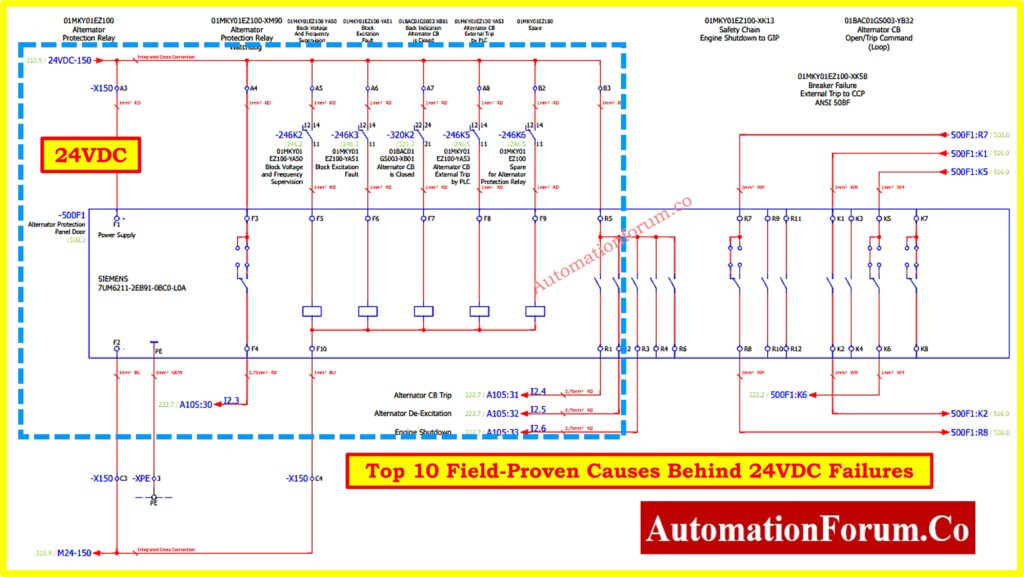
- Top 10 Field-Proven Causes Behind 24VDC Failures
- Cause 1. The Illusion of No-Load Measurements
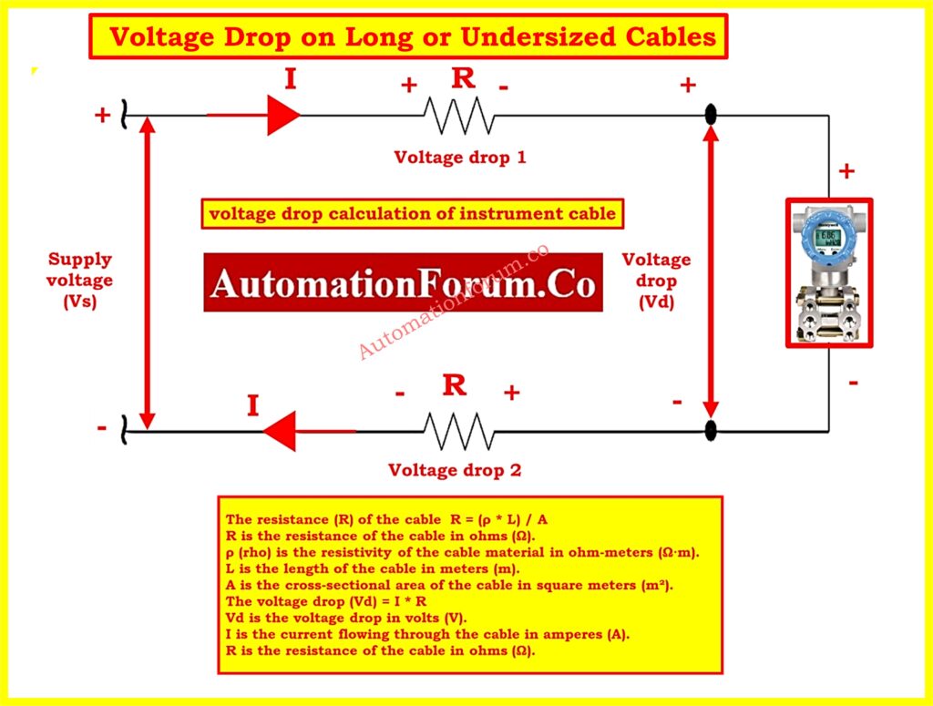
- Cause 2. Voltage Drop on Long or Undersized Cables
- Cause 3. Loose Terminals, Oxidation, and Bad Crimps
- Cause 4. Shared Power Supply Problems – The Domino Effect
- Cause 5. High Inrush or Operating Current Devices
- Cause 6. Analog vs Digital Signal Sensitivities
- Cause 7. Testing the Right Way – Under Load Conditions
- Cause 8. Junction Box Wiring: Project Checklist Essentials
- Cause 9. Advanced Tip: Simulate Load to Diagnose Drops
- Cause 10. From Guesswork to Real Diagnostics
- Suggestions for Engineers and Technicians
- Quick Troubleshooting Checklist for Engineers and Technicians
- Real-World Case Study: Pressure Transmitter Not Responding
- Proactive Design-Phase Measures to Prevent 24VDC Issues
- Final Takeaway for Field Teams and Project Engineers
- Frequently Asked Questions (FAQ) About 24VDC in Industrial Automation
In the field of instrumentation and control systems, 24VDC is the backbone powering everything from analog transmitters and digital sensors to actuators, solenoids, and field I/O modules. In design documents and datasheets, it’s a constant. But in the real world? It can be surprisingly unstable.
One of the most common mistakes during commissioning or fault-finding is assuming that “If my multimeter shows 24VDC, then everything must be working.”
Unfortunately, this is far from true. The presence of voltage does not guarantee performance. A transmitter may still refuse to respond, a digital input may not toggle, or a solenoid may fail to actuate even when the power supply shows 24VDC.
The secret? You must measure under real load conditions.
Top 10 Field-Proven Causes Behind 24VDC Failures
Cause 1. The Illusion of No-Load Measurements
Let’s be clear voltage without current means very little. You can measure 24.2VDC at a terminal with a multimeter, but the instant the device demands power, the voltage can dip sharply. That dip, often invisible to standard checks, is enough to make the equipment malfunction.
This is especially dangerous with smart field devices like HART transmitters, flow meters, or analytical instruments. They might appear powered up, but behave erratically or drop communication if they are underpowered.
Cause 2. Voltage Drop on Long or Undersized Cables
Real-World Symptom:
- Transmitter powers up, but gives unstable or noisy 4-20mA signal.
- Remote I/O modules randomly reset.
Technical Insight:
DC voltage drop = Current (I) × Resistance (R) of the wire. Longer cables or smaller cross-sections (like 0.5 mm²) increase resistance. At just 100 meters, a 20mA signal loop can lose over 1V if improperly sized.
In critical applications, like remote flowmeters in tank farms or water treatment plants, voltage drop becomes a serious issue.
Fix:
Use a voltage drop calculator in the design phase. Always validate that minimum 22VDC reaches the farthest device under full current draw.
Learn the key differences between Live Zero vs Dead Zero in 4-20 mA signal standards: Understanding the Difference Between Live Zero and Dead Zero in 4 to 20 mA Signals
Cause 3. Loose Terminals, Oxidation, and Bad Crimps
Even with the best cable routing and wiring plan, poor terminations kill signal integrity.
Real-World Symptom:
- Signal loss during vibration or thermal cycles.
- Devices power up, then drop offline unpredictably.
Root Cause:
- Stranded wires improperly inserted.
- Over-crimping or under-crimping.
- Screw terminals not tightened to specification.
Poor connections introduce high resistance, which only reveals itself when current flows. The result is voltage sag, heating, or intermittent open circuits.
Fix:
- Always use ferrules on stranded cables.
- Crimp with ratcheting tools.
- Pull-test and torque-check every terminal, especially in JB (Junction Box) terminations.
Cause 4. Shared Power Supply Problems – The Domino Effect
Real-World Symptom:
- Multiple transmitters resetting together.
- HART communication errors across several loops.
Technical Insight:
Connecting 10-15 devices on a single 24VDC power supply may look fine if total current is within specification. But inrush current, ground loops, or switching transients can destabilize the entire supply. One faulty device can pull down the rail, affecting all others.
This problem is compounded in hazardous area applications using isolators and barriers, where voltage clearance is critical.
Fix:
- Isolate power supplies by function (e.g., AI, AO, DI, DO).
- Use buffer modules or decoupling diodes for sensitive signals.
- For analog loops, prefer dedicated loop-powered isolated supplies.
Master the use of loop calibrators for simulating and testing 4-20mA signals in the field: How to simulate 4-20ma signal with Loop Calibrator ?
Cause 5. High Inrush or Operating Current Devices
Some devices may draw very low current when idle but spike dramatically during operation.
Examples:
- Solenoid valves
- On/off motorized valves
- Radar level transmitters during burst mode
- Analytical sensors with heaters or blowers
Symptom:
- Device fails to actuate or resets immediately after triggering.
Cause:
Most general-purpose 24VDC power supplies can’t respond fast enough to inrush current. The result is a voltage dip lasting milliseconds, invisible to a multimeter but enough to reset a microcontroller.
Fix:
- Size power supplies based on dynamic load, not just steady-state.
- Add local buffer capacitors to smooth inrush demands.
- Monitor with an oscilloscope or a fast-sampling data logger to capture transients
Understand why 4-20mA and 3-15psi are still preferred over their 0-based alternatives: Why not use 0-20mA & 0-15psi instead of 4-20mA & 3-15psi?
Cause 6. Analog vs Digital Signal Sensitivities
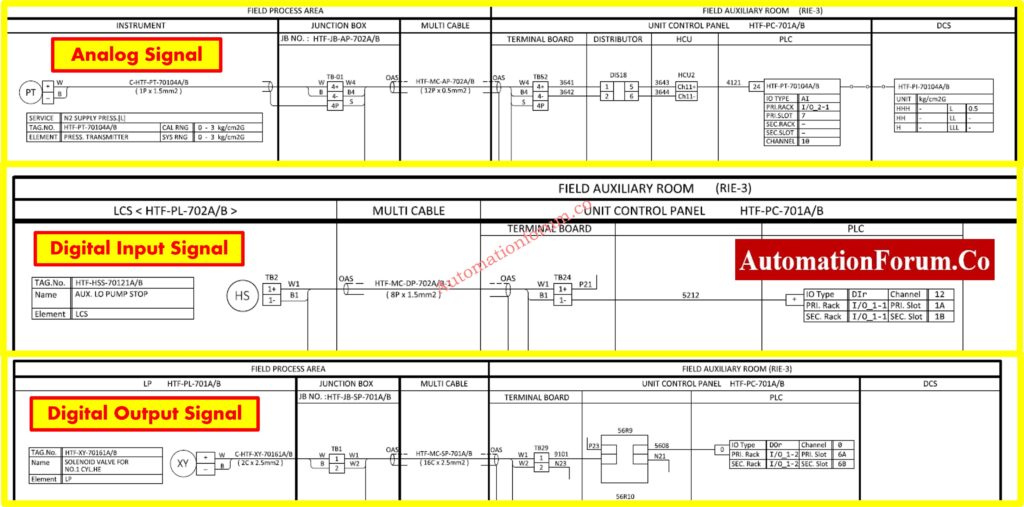
Different I/O types react differently to voltage issues.
Analog (4-20mA):
- Transmitter current accuracy drops with low voltage.
- Some devices stop transmitting entirely below 19VDC.
Digital Inputs:
- Logic level thresholds may not recognize low signals.
- Optical isolators inside DI modules may not activate.
Digital Outputs:
- Output may latch ON, but the load (e.g., solenoid) doesn’t activate due to insufficient voltage.
Pro Tip:
- Use a true RMS multimeter to check voltage ripple.
- For analog signals, ensure loop resistance and voltage remain within device specification (usually >12V at the transmitter terminals).
Refer the below link to Explore why 24VDC is the standard in modern industrial automation systems:
Cause 7. Testing the Right Way – Under Load Conditions
A key shift in mindset: Never test 24VDC open-circuit. You need to see how it behaves when current flows.
Tools:
- Clamp meter (DC current measurement)
- Logging multimeter (voltage over time)
- Oscilloscope (to capture dips and spikes)
- Loop calibrator (to simulate 4-20mA under load)
Test Points:
- Power supply output terminals
- Field device terminals under operation
- Terminal blocks inside JB and marshalling panels
Step-by-step guide to troubleshooting common issues in 4-20mA analog signal loops: How to do troubleshooting of a 4-20mA loop?
Cause 8. Junction Box Wiring: Project Checklist Essentials
In project installations, many 24VDC issues originate in the junction box (JB).
Common Issues:
- No separation between analog and digital cores.
- Inconsistent ferrule usage.
- Improper grounding or shielding causing voltage shifts.
Project Team Best Practice:
| JB Wiring Checklist Item | Why It is Important |
| Separate AI, AO, DI, DO cores | Prevents cross-talk |
| Label wires with terminal tags | Fastens troubleshooting |
| Use gland plates with proper sealing | Prevents moisture that causes oxidation |
| Provide equal potential grounding | Avoids floating voltages |
| Use tie wraps or DIN rail clamps | Prevents tug damage from cable weight |
Cause 9. Advanced Tip: Simulate Load to Diagnose Drops
If a device fails during operation but shows 24VDC at rest, try simulating the load.
Example:
- Place a 10W resistor (1.2kΩ) across the terminals of the suspected supply.
- Monitor voltage.
- If it drops below 22VDC your supply or wiring is the culprit.
This method is useful when devices are not available but you want to validate wiring integrity.
Follow best practices for clean and correct wiring of 4-20mA current loops: How to do the 4-20mA Wiring?
Cause 10. From Guesswork to Real Diagnostics
Here’s a recap of what you must remember when troubleshooting 24VDC instrumentation signals:
Don’t Trust Only a Voltage Number
- Voltage may look fine at rest.
- Measure under actual current draw.
Think Like the Device
- Ask: What voltage is available when it’s working hardest?
Test Like a Pro
- Measure both voltage and current.
- Use logging tools to catch transients.
Respect Cable Length and Quality
- Undersized or long cables are voltage killers.
- Crimps, terminals, and grounds matter just as much.
Separate and Isolate
- Protect sensitive loops with dedicated channels.
Suggestions for Engineers and Technicians
If your instrumentation device isn’t working, but 24VDC appears fine don’t assume.
Test under load. Verify cable drop. Check terminations. Isolate interference.
This level of detail separates guesswork from professional field diagnostics.
When project teams apply these lessons early during design and commissioning, they prevent countless startup delays and service calls later.
Learn the benefits and use cases of loop-powered field instruments in control systems: What is the Purpose of Loop Powered Instruments?
Quick Troubleshooting Checklist for Engineers and Technicians
| Item | Checkpoint | Why it is Important |
| Cable Length & Size | Use calculator to estimate drop | Prevents under-voltage at far ends |
| Terminal Tightness | Tug-test and re-torque all connections | Avoids hidden open circuits |
| Crimp Quality | Inspect visually and with pull test | Bad crimps mimic faults |
| Power Supply Sizing | Compare actual load vs spec | Prevents sag under multiple devices |
| Startup Current | Observe current spike behavior | Some loads draw extra at start |
| Measure Under Load | Keep device active while measuring | True voltage behavior only visible then |
Note: Use a data-logging multimeter or oscilloscope to spot sudden dips in voltage when multiple devices switch.
This technique is gold during plant commissioning or troubleshooting of intermittent faults.
Real-World Case Study: Pressure Transmitter Not Responding
A commissioning team at a refinery reported that a pressure transmitter located near a flare stack was not responding to HART communication. The multimeter at the marshalling panel showed a healthy 24.3VDC, yet the control system showed a flatlined analog input.
Initial assumption: The transmitter is faulty.
Reality: The cable run from the panel to the transmitter was nearly 190 meters, using a 0.75 mm² cable. When measured at the transmitter under load, the voltage dropped to 19.1VDC, below the minimum operating range for the smart transmitter.
Once replaced with a 2.5 mm² cable, the voltage stabilized above 22.5VDC and the transmitter began responding immediately.
Lesson learned: Always verify voltage at the device, during actual operating conditions especially in long cable runs.
Refer the below link to Discover how to calculate and avoid voltage drops in PLC wiring during design and installation
Proactive Design-Phase Measures to Prevent 24VDC Issues
Troubleshooting is essential, but the best engineers prevent issues during design. Here’s how:
- Include voltage drop analysis in cable sizing calculations, especially for field devices >100m away.
- Oversize power supplies by 30% clearance for inrush tolerance.
- Physically separate analog and digital JB wiring to reduce induced noise and voltage shift.
- Distribute multiple smaller power supplies close to device clusters rather than one large centralized unit.
Doing this not only improves reliability but also minimizes startup headaches.
Final Takeaway for Field Teams and Project Engineers
Voltage at the panel ≠ voltage at the device.
The only voltage that matters is what your device receives while doing its job. Never assume, always verify under load, under distance, and under dynamic conditions.
This awareness transforms your troubleshooting from trial-and-error into targeted engineering saving hours of downtime, rework, and misdiagnosis.
Frequently Asked Questions (FAQ) About 24VDC in Industrial Automation
1. Are 24V and 24VDC the same?
Not exactly.
24VDC is 24 volts direct current, while 24VAC is alternating current. Devices like relays are designed specifically for DC or AC using the wrong type can cause malfunction.
2. What does 24VDC mean?
It stands for 24 Volts Direct Current a steady, one-directional voltage commonly used in automation systems, especially for powering PLCs, sensors, and actuators.
3. What is the voltage tolerance for 24VDC?
Typically ±5%, meaning acceptable voltage ranges from 22.8V to 25.2V. Actual tolerance may vary based on device type, cable length, and wire size.
4. Why use 24VDC in confined spaces?
24VDC is safer in wet or tight areas due to lower shock risk. It’s ideal in humid or hot environments where AC lighting or power may not be suitable.
5. Why do PLCs use 24VDC?
Because it’s safe, reliable, and widely compatible with field devices. Most industrial sensors, I/O modules, and actuators are designed to run on 24VDC.
Refer the below link to Understand the technical reasons why current signals outperform voltage in industrial environments