What is the purpose of using a 4-20mA signal in process automation?
Industrial automation is carried out by transmitting signals from field devices to the controller and this signal will be a 4 -20mA analog signal. In order to do the transmission of physical signals such as pressure, temperature, flow, and level we need to convert it to an electrical signal and this can be achieved with the help of a transducer.4-20mA is a standard signal which can be used to do this transmission. So these signals would reach the controller of a control system like the DCS and thus the process can be controlled. The 4-20mA signal which is used for the transmission would represent the percentage of a process variable. In earlier days industrial control was achieved by pneumatic systems and during that time 3psi -15 psi was used as a standard signal. The 3 psi is zero percent and 15 psi is the hundred percent. Less than 3 psi was considered as a fault condition. Later 3-15 psi was replaced by 4-20mA.
How 4-20mA control loop is utilized for industrial process control?
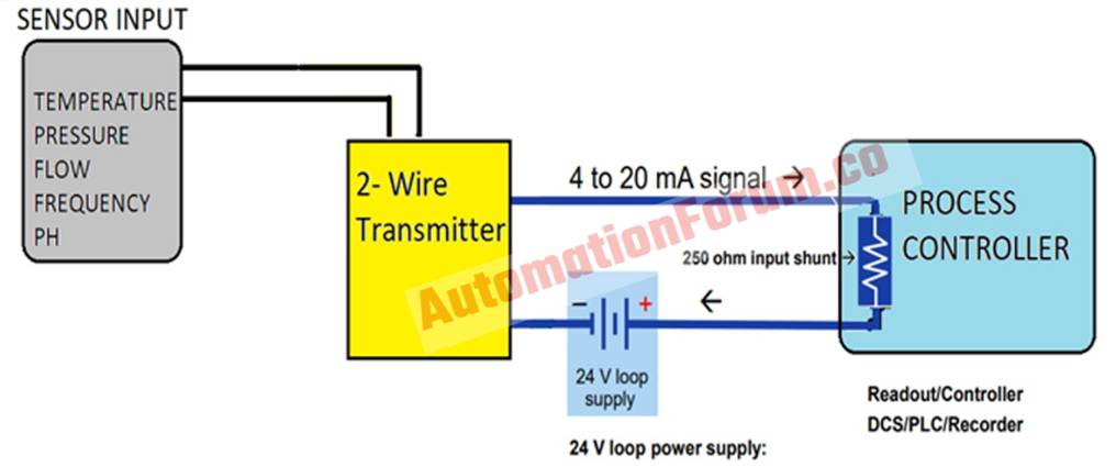
The transmitter would convert the sensor inputs like flow or temperature to a 4-20mA signal. It would take or draw power from an external loop power supply. The transmitter would regulate the 4-20mA signal in the power circuit by drawing the power from the supply. The 4-20mA signal which is transmitted to the controller is an analog current signal and when it reaches the controller it would be converted to a digital signal.
The 4-20mA signal will be interpreted by the controller as the pressure or temperature being measured in the process. So based on the received signal the controller would issue a command signal to the final control element like a valve so that the process pressure and temperature can be controlled.
Why 0 – 20mA is not used instead of 4-20mA?
The problem which is caused while using a 0 -20mA is that we won’t be able to differentiate between the connection break and the minimum field value. So by using a 4-20mA signal the internal circuits would be capable to distinguish between the connection break and the minimum field value. So, if the value is minimum then the transmitter would give 4mA while during the connection break it would give 0mA.
4mA is referred to as Engineering zero
0mA is referred to as dead zero.
Why current signals are used instead of voltage signals for process automation?

The voltage signal is not used for the signal transmission from the field device to the controller is due to the fact that the voltage signal would drop down over long distances. So due to this transmission is done in the current loop. We can transmit information over long distances to a remote location via a current loop. The operation of the current loop is really simple, the output voltage of the sensor would be converted to a proportional current value. This will be transmitted to the receiver section with 4mA representing the zero level output and 20mA representing the full-scale output of the sensor.
The receiver in the control station would convert the current into voltage and this will be further processed by a controller. Transmitting the current over long distances would create voltage drops. These voltage drops can be considered as loop drops and it won’t reduce the 4-20mA current if the transmitter and the loop supply can compensate for these drops. The current magnitude in the loop won’t be affected by the voltage drop in the system. Current in the loop would be equivalent at any point in the loop. There could be a lot of noise in an industrial environment, the low impedance of the current loop system makes it less sensitive to the created noise.
Take away points
- Voltage drop while using voltage signals
- Voltage signals are affected by noise
- Current signals can transmit signals for long-distance
What is the reason for choosing 4-20mA instead of 1 – 5V?
This is due to the fact that the 1 -5V signal would drop due to the line resistance. So if the distance between the field device and the controller is more then, the field value won’t be properly represented by the 1-5V signal. But in the case of the 4-20mA signal there won’t be any problem like this, it can be transmitted over a long distance from the field without dropping the signal value.
Why 4mA is used in the lower range and why 20mA is used in the upper range of 4-20mA signal?

In earlier days the transmitter utilized the pneumatic pressure signal for the transmission and after that, electronic chips replaced it. These chips would require at least 3mA of current to function properly. We are using 4mA as a lower range instead of 0mA and this is due to the fact that if we use 0mA then there won’t be any power to drive the field instrument.
If we use 0mA instead of 4mA then we won’t be able to recognize the zero value of the sensor or the transmission signal problem. Because of the voltage drop problems voltage signals are not transmitted, so the voltage signal in the transducer will be converted to a current signal. The transmitter would convert the voltage signal to the current signal, and then this signal will be transmitted through copper wires to the controller input card. In the controller section, a 250-ohm resistance is used and this is used to convert the 4-20mA into 1-5V. A voltage range of 1-5V is common due to the fact that most of the early microcontrollers utilized a 5V supply. The signal will be converted back to a voltage signal of 1-5V DC and it is done so that the input card can determine the value.
According to Ohm’s law V = IR
Where R is the resistance, I is the current and V is the voltage
1 Ampere = 1000mA
| CURRENT (mA) | RESISTANCE (ohms) | VOLTAGE V = I * R |
| 0 | 250 | 0 |
| 4 | 250 | 1 |
| 8 | 250 | 2 |
| 12 | 250 | 3 |
| 16 | 250 | 4 |
| 20 | 250 | 5 |
So that’s why 20mA is used as the upper range of the 4-20mA signal.
What are the major advantages of the 4-20mA signal?
There are many advantages for the 4-20mA current loop
- They are not sensitive to wire resistance
- Insensitive to multiple receivers (shunts)
- Easy signal filtering
- Low-cost wiring
- Long-distance transmission
- Lower cost than the digital signal transmission
Loop validation
The zero percent of the sensor is transmitted as 4mA, the open circuits in the loop can be detected. If this instrument measures a value that is less than 4mA then the instrument would be able to determine that there is a fault in the loop. If the receiving instrument measures a value higher than 20mA and then also the instrument would be able to determine the problem with the loop.
Loop resistance
The major advantage of the 4-20mA signal is that they are able to function over long-distance cable. So when compared to a voltage signal the loop current signal won’t be affected by the voltage drop till the supply voltage is capable to provide the required loop current.
Immunity to noise
The current loop in a 4-20mA system has less impedance and due to this, the noise immunity of the signal is high when compared to a voltage-driven system.
What are the different types of 4-20mA wiring arrangements?
Loop powered(2 wire)

In this type of arrangement, the sensor would be usually a two-wired device. The two wires would be used to both power the sensor and also receive the signal from the sensor. In this type of wiring arrangement, the transmitter and the sensor are remotely located and a local power supply is not utilized. The input circuitry floats with respect to the loop supply ground.
Advantages of loop-powered wiring
- Power consumption is really low
- Transmitter only requires two cable cores
- No need for local power
Disadvantages of loop-powered wiring
- This type of wiring configuration would draw some current in a fault condition and due to this fault signaling of the transmitter cannot be set at 0mA
- Output options are limited
- This type of arrangement is not suitable for transmitters that utilize more power
Nonisolated (3 wire)

This type of arrangement is the most used for the 4-20mA wiring. So in this wiring arrangement, the transmitter and the control panel would utilize the same power lines. In this wiring arrangement the transmitter would be located close to the power supply and the input is referenced to power supply ground.
Advantages
- We can use a common power supply for the controller and the transmitter
- There are only three cables used for the transmitter
- Lower cost than a four-wire arrangement
Disadvantages
- In case of any electrical interference, then it could be transmitted along the signal line
Field powered (4 wire)

This is used for the field-powered arrangement, the sensor would be mostly a four-wired device. Two wires would be used to power the sensor, the remaining two wires would be utilized to transmit the signal from the sensor to the receiver. The receiver would be composed of the resistor to convert the loop current into voltage.
Advantages of field power wiring
- In case if there is any electrical interference in the voltage supply lines then it won’t be transmitted to the 4-20mA signal line
- There won’t be any voltage drop
Disadvantages of field powered wiring
- Each transmitter would need an additional cable core
- Expensive due to more wiring
- The transmitter and the control panel would need a separate power supply
What are the problems that could happen in a 4-20mA loop?
- Bad termination or insulation corrosion would affect the operation.
- The overloaded power supply would affect the loop operations
- If the controller doesn’t interpret the mA signal properly then there won’t be any process control
- Problems in the transmitter would affect the operation if the transmitter doesn’t convert the mA signal according to the measured sensor input
- Problems in sensor would affect the process operation too