- Real Plant Problems Caused by Improper Grounding in Industrial Systems
- What is Grounding in Instrumentation Systems and Why It Is Critical
- Types of Grounding in Instrumentation: Safety Grounding vs Signal Grounding
- Why Improper Grounding Creates Noise in Instrumentation Signals
- Ground Potential Difference in Industrial Plants Explained
- What is Single Point Grounding in Instrumentation Systems
- Advantages of Single Point Grounding
- Limitations of Single Point Grounding
- Typical Applications of Single Point Grounding
- Practical Understanding of Single Point Grounding for Field Engineers
- What is Multiple Point Grounding in Industrial Systems
- Advantages of Multiple Point Grounding
- Limitations of Multiple Point Grounding
- Practical Understanding for Field Engineers
- Single Point vs Multiple Point Grounding: Key Differences Explained
- What is Ground Loop Problem in Instrumentation Systems
- Real Industrial Case Studies of Ground Loop Issues
- When to Use Single Point Grounding in Process Plants
- When to Use Multiple Point Grounding in Industrial Applications
- Hybrid Grounding Concept in Modern Control Systems
- Best Grounding Practices for Instrumentation Engineers
- Common Grounding Mistakes in Industrial Plants
- Grounding Troubleshooting Checklist for Field Engineers
- Conclusion: Choosing the Right Grounding Method in Instrumentation
Grounding is not just a safety requirement. It is a key factor that determines signal quality, system stability, and communication reliability. Even when all the instruments are set up correctly, a system that isn’t well grounded can act in strange ways.
Real Plant Problems Caused by Improper Grounding in Industrial Systems
- 4 to 20 mA signals keep changing even when the process parameters stay the same.
- Analog input values in a PLC or DCS that fluctuate randomly without any changes in the field
- Sudden spikes or noise showing up in historian trends
- Intermittent loss of connection in Ethernet, Modbus, or fieldbus networks
- Control valves are hunting because the feedback signals are not reliable.
- False alarms or trips caused by loud signals
- Instruments act differently at night and during the day because of load changes.
- Noise only happens when motors or VFDs start up
- Signal distortion in lengthy cable runs caused by wrong return pathways
- Sensitive electrical modules fail because of changes in ground potential.
Grounding has a direct effect on how well a system works because it gives all electrical signals a reference point and a way to get back. You can’t trust any measurement if you don’t have a steady reference.
Stop Shield Noise Fast With This Calculator: Shield Grounding Noise Calculator for Instrumentation: A Practical Engineer Guide
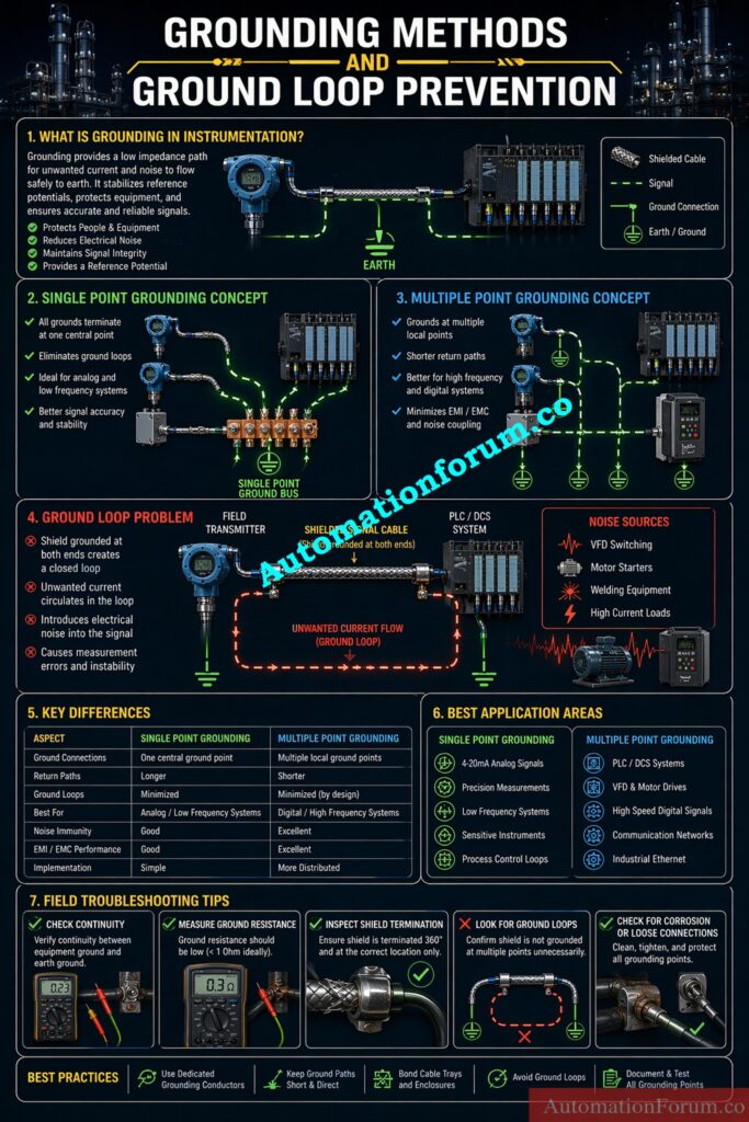
What is Grounding in Instrumentation Systems and Why It Is Critical
Grounding in instrumentation systems is setting a reference potential (zero volts) and making a low-resistance conduit for unwanted current to flow safely.
Core Functions of Grounding in Industrial Automation
- Gives measurement signals a steady reference voltage
- Makes ensuring that signal currents have the right return path
- Lessens noise and electromagnetic interference
- Keeps equipment safe from electrical problems and spikes
- Keeps the signal strong over long distances
- Stops static charge from building up in equipment
- Helps safety devices work properly when there are problems
- Makes ensuring that PLC and DCS systems work the same way every time.
Grounding makes sure that the system is safe and works well.
Types of Grounding in Instrumentation: Safety Grounding vs Signal Grounding
What is Safety Grounding in Industrial Systems
- Links the body of the equipment and the panels to the ground
- Keeps people from getting shocked by electricity
- Gives a way for fault current to flow
- Linked to the plant’s ground grid
- Needed for all electrical devices
- Made to carry a lot of current safely
- Usually connected with wires that have low resistance
What is Signal Grounding in Instrumentation
- Gives a reference for measurement signals
- Used in both digital and analog systems
- Must be free of noise and dirt
- Often cut off from grounding power
- Important for PLC, DCS, and transmitter signals
- Needs careful planning to avoid problems
Refer the below link for the Grounding and Bonding in Instrumentation and Control Systems
https://automationforum.co/grounding-and-bonding-in-instrumentation-control-systems/
Why Improper Grounding Creates Noise in Instrumentation Signals
Noise is generated when unwanted current flows through signal circuits.
- Ground impedance makes the voltage go down.
- Multiple grounding paths create circulating currents
- Cables get voltage from electromagnetic fields.
- Long grounding paths make inductance go up.
- High-frequency signals make grounding problems worse.
- Bad shielding turns cables into antennas.
A good grounding system cuts down on EMI by giving undesired signals a controlled way to go through.
Understand Electrical Grounding Types Without Confusion: What is grounding in electricity and Types of grounding
Ground Potential Difference in Industrial Plants Explained
- The ground voltages in different parts of the plant are variable.
- Because of different load currents and resistance in the ground
- A little variation in voltage can make current flow.
- This current goes through signal circuitry.
- Causes inaccuracies in measurement and instability
- Worse in big factories with systems that are spread out
Ground Cable Screens Correctly And Eliminate Noise: Cable screen, Grounding cable screen
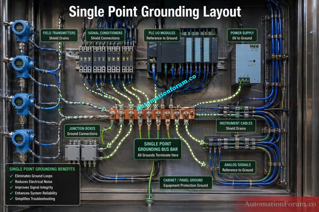
What is Single Point Grounding in Instrumentation Systems
Definition of Single Point Grounding with Practical Example
Single point grounding indicates that all of the grounding connections in a system are connected to one common reference point. This way, the whole installation has one zero volt reference. In simple plant terms, it is a grounding method where all sensitive instruments, signal shields, and reference returns are tied to one approved grounding node instead of being connected at several different locations.
This method is widely used in instrumentation because low level signals are very sensitive to noise, ground potential differences, and circulating currents. When more than one grounding path exists, unwanted current can travel through the signal system and disturb measurement accuracy. Single point grounding avoids this problem by forcing all returns to follow one defined path.
This method is extremely useful for analog systems in process plants, like 4 to 20 mA loops, transmitter signals, and other low-level measurements where even a small amount of electrical noise can change the value.
Calculate IS Earth Faults Before Field Disaster: IS Barrier Earth Fault Current Calculator | Intrinsic Safety Loop Design Tool
Key Characteristics of Single Point Grounding
- One central grounding node is used for the entire circuit or signal group.
- All equipment and signal references are connected to the same grounding point.
- No parallel return paths are allowed, which helps prevent unwanted current circulation.
- The layout is normally set up in a star shape, with each device going back to one main point.
- A grounding bus bar or earth bus is often employed as the point of reference.
- All signals that are coupled stay at the same potential.
- The system is easier to control because the grounding structure is simple and clearly defined.
- It is generally preferred for sensitive instrumentation and low frequency signal circuits.
Refer the below link for the Understanding Zener vs Galvanic Isolation in IS Loops for 4 to 20 mA Systems
Advantages of Single Point Grounding
- When done right, it gets rid of ground loops totally.
- It stops current from flowing between devices, which is one of the main reasons for signal noise.
- It gives measurement signals a stable reference voltage.
- It makes analog measurements like pressure, flow, level, and temperature more accurate.
- It cuts down on noise pickup in low-level communications and shielded cable systems.
- It simplifies grounding design, installation, and documentation for EPC and maintenance teams.
- It makes troubleshooting easier because the grounding path is clear and easy to inspect.
- It helps reduce signal distortion in circuits that measure things very carefully.
- It is ideal for low frequency systems where signal stability is more important than very short grounding paths.
Why Single Point Grounding is Preferred for Analog Signals
In practical terms, single point grounding gives instrumentation engineers a controlled and predictable reference. That is why it is typically used in panels, marshalling cabinets, and transmitter circuits where accuracy is very important.
Single point grounding minimizes noise by eliminating multiple current paths, which reduces the chance of unwanted signal interference.
Check Earthing Resistance Before It Fails: Instrument Earthing Resistance Calculator for Process Industries Complete Engineering Guide
Limitations of Single Point Grounding
- Long grounding paths can make things less effective and more resistant.
- More noise can get into the signal if the grounding path has a higher impedance.
- Voltage drop may occur in long cable runs, especially in large plants.
- It is not suitable for high frequency systems because inductive effects become significant.
- At higher frequencies, grounding conductors can behave less like a simple wire and more like an impedance path.
- It can be difficult to implement in large plants with widely distributed equipment.
- Careful layout planning is required to make sure the single reference point is practical and effective.
The main weakness of single point grounding is that it works best only when the grounding path remains short and the system frequency is low. If the system becomes too large or too fast, the single path may no longer provide the best noise control.
Build Reliable Instrument Earthing The Right Way: Instrument Earthing Systems
Typical Applications of Single Point Grounding
- Pressure transmitters
- Temperature transmitters
- Flow transmitters
- Analyzer systems
- Analog input modules
- Intrinsically safe systems
- Laboratory instruments
Decode Earthing Drawings Without Costly Mistakes: Earthing Drawing
Practical Understanding of Single Point Grounding for Field Engineers
In the field, single point grounding is usually applied where the signal must remain clean and stable. For example, a transmitter sending a 4 to 20 mA signal to a PLC analog input should not have its shield grounded at both ends unless the design specifically requires it. If both ends are grounded, the system can develop a loop and create noise.
This method is especially useful when:
- the signal is low level,
- the cable run is moderate,
- the equipment is sensitive,
- and the process requires accurate measurement.
A good single point grounding system gives the engineer a clean reference and reduces the chance of mysterious signal fluctuations during operation.
Check Home Earthing Properly Before Trouble Starts: How to check if the earthing is properly done in our home?
What is Multiple Point Grounding in Industrial Systems

Definition of Multiple Point Grounding with Industrial Examples
Multiple point grounding means equipment is connected to earth at several different locations instead of one single reference point. In this method, the grounding system is distributed across the plant, panel, or installation so that each section has its own local grounding connection.
People often utilize this method when there are high-frequency communications, circuits that switch quickly, or big distributed systems. In these kinds of systems, a single long grounding line may cause too much impedance. To keep the return path short and effective, it’s better to use more than one grounding point.
In process industries, multiple point grounding is often used in systems where speed, noise suppression, and low impedance are more important than absolute simplicity. It is very popular in digital control systems, power electronics, communication networks, and VFD panels.
Key Characteristics of Distributed Grounding Systems
- Multiple grounding connections are provided across the system instead of one central point.
- A ground grid or mesh structure is commonly employed to help spread out the return current.
- Grounding paths are kept short to reduce impedance and inductive effects.
- The system is designed as a distributed grounding arrangement.
- Parallel return paths are allowed, which helps high frequency currents return more efficiently.
- A ground plane notion is a common feature of control panels, electronic systems, and communication cabinets.
- The method supports wide installations where devices are physically spread out.
- It is generally used where low impedance matters more than avoiding every possible loop.
Stop Shield Noise Fast With This Calculator: Shield Grounding Noise Calculator for Instrumentation: A Practical Engineer Guide
Advantages of Multiple Point Grounding
- It reduces grounding impedance significantly by providing several low resistance paths.
- It provides shorter current return paths, which is very important in high frequency environments.
- It improves high frequency performance because the grounding path remains short and effective.
- It makes EMI suppression better by giving noise a better way to get to the ground.
- It is suitable for digital systems where fast signal transitions are common.
- It works well in switching environments such as VFDs, servo drives, and power electronics.
- It reduces inductive effects in grounding conductors, especially when compared with long single return paths.
- It works well for big installations that are spread out and can’t have a central ground point.
- It makes the system more reliable by spreading the grounding network over many sites.
Multipoint grounding lowers impedance and makes it easier to deal with high-frequency noise.
Understand Instrument Earth Before Signal Problems Spread: Understanding Instrument Earth (IE) in Industrial Automation – Complete Guide for Engineers
Limitations of Multiple Point Grounding
- If the system isn’t constructed well, it could cause ground loops.
- There can be circulating currents between distinct ground points.
- If shields and references aren’t correctly terminated, noise can get into signal circuits.
- Troubleshooting becomes difficult because multiple grounding paths make fault tracing more complex.
- The system design is more complicated than single point grounding.
- It requires strict grounding discipline during installation and maintenance.
- Ground potential differences become very important and can create unexpected noise problems.
- If not properly planned, the system may work well in one area and fail in another.
Typical Applications
- VFD systems
- Motor control centers
- PLC communication networks
- Ethernet systems
- High speed digital systems
- Power electronics
Spot Noise And Signal Drift Before Shutdowns: Noise and Signal Stability Observation for Running Inspection in Instrumentation and Control Systems
Practical Understanding for Field Engineers
Multiple point grounding is mainly used when the system has fast switching activity or high frequency noise. In these cases, a long single grounding path can behave like an unwanted impedance and make noise problems worse. By grounding at several locations, the system gives noise a short return route and reduces interference.
This method is especially useful in:
- large panels with many electronic devices,
- systems with fast digital communication,
- and installations where VFDs or other switching devices generate strong electrical noise.
For example, in a VFD panel, the switching frequency can create strong electromagnetic interference. A multiple point grounding method works better than a long single path to keep this noise in check. Similarly, in Ethernet or digital communication systems, low impedance grounding improves stability and performance.
However, engineers must be careful. Multiple point grounding is not the right choice for every signal type. If it is used in low level analog loops without proper design, it may introduce noise instead of removing it.
Practical Field Note:
Master IEC 60079-14 Before Hazardous Area Mistakes: IEC 60079-14 Explained: Complete Guide to Hazardous Area Installation for Instrumentation and Control Systems
Single Point vs Multiple Point Grounding: Key Differences Explained

| Parameter | Single Point Grounding | Multiple Point Grounding |
| Ground Path | Uses one common centralized grounding point for the entire system. All returns are brought back to the same reference node. | Uses several grounding points distributed across the system. Equipment is grounded locally at different locations. |
| Frequency Suitability | Best suited for low frequency and sensitive analog circuits where signal stability is important. | Best suited for high frequency and fast switching systems where short return paths are required. |
| Ground Loop Risk | Very low, because there is only one return path and no circulating current path is created. | Higher, because multiple paths can create circulating current if not designed carefully. |
| Signal Type | Commonly used for analog signals such as 4 to 20 mA loops, transmitters, and low level measurements. | Commonly used for digital systems, communication networks, and high speed control circuits. |
| Impedance | Usually higher because the grounding path may be longer and less direct. | Usually lower because the grounding path is shorter and more direct. |
| Troubleshooting | Easier to inspect, trace, and maintain because the system has one clear grounding reference. | More complex to troubleshoot because multiple grounding points can make fault tracing difficult. |
Application-Based Selection Guide
- Single point grounding is preferred where signal accuracy is more important than speed.
- Multiple point grounding is preferred where noise control at high frequency is more important.
Get JB Grouping Right Before Installation Chaos: JB Grouping in Industrial Automation and Instrumentation – Complete Practical Guide
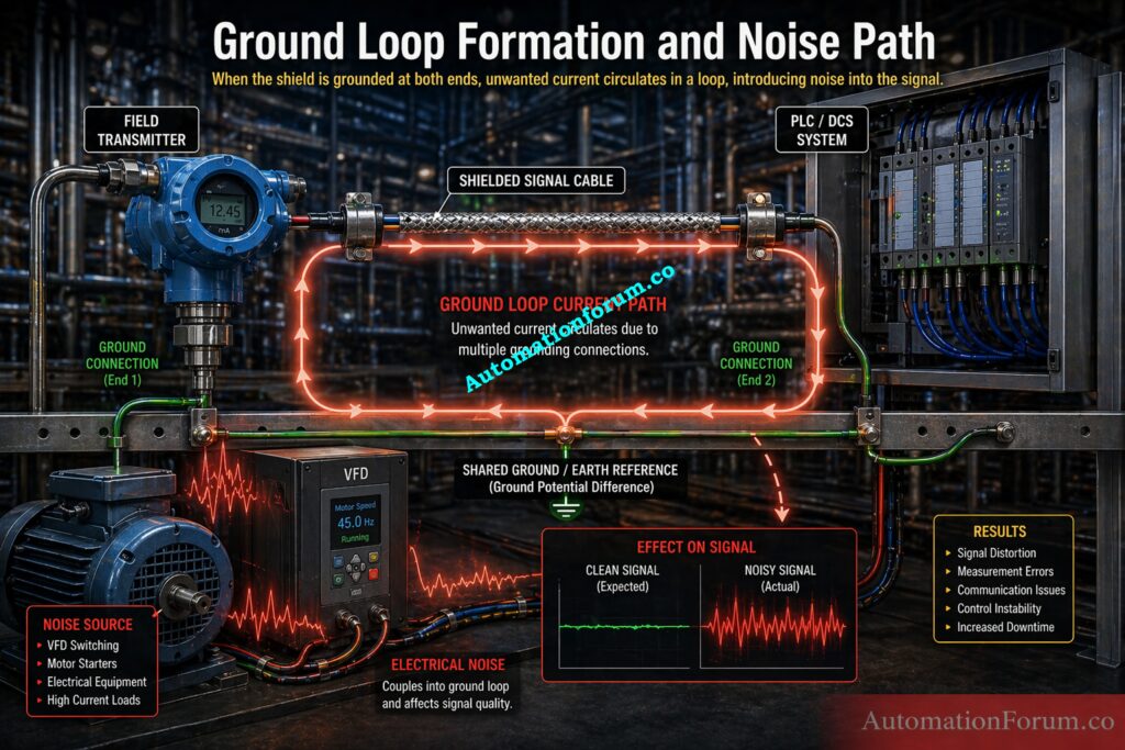
What is Ground Loop Problem in Instrumentation Systems
What is Ground Loop in Instrumentation Systems
Ground loop is one of the most serious and most misunderstood problems in instrumentation systems. It happens when unwanted current starts flowing through a loop formed by multiple ground paths. In a healthy instrumentation system, ground should act only as a reference and a safe discharge path. When more than one ground path exists between the same points, the system can behave like an unintended circuit, and that creates noise, instability, and measurement errors.
This issue becomes especially important in process plants where sensitive analog signals, shielded cables, PLC inputs, and communication networks all coexist in the same area. Even a small ground loop can cause large practical problems in a running plant.
How Ground Loop Occurs in Industrial Plants
- Equipment is grounded at more than one location
- Ground potentials at those locations are not exactly equal
- A closed loop path gets formed through the grounding network
- Current starts flowing through that loop
- That current interferes with the intended signal path
Troubleshoot PLC Analog Outputs Like A Pro: Troubleshooting Analog Output Signals in PLC Loops – Advanced Scenario-Based Quiz for Process Industries
Technical Behavior of Ground Loop Current
- A voltage difference between ground points drives the unwanted current
- The current does not stay only in the earth conductor
- It may travel through cable shields, signal commons, or instrument reference lines
- Noise gets superimposed on the measurement signal
- The transmitter or input module starts seeing an unstable reference
- The system begins to show drifting or jumping values
Ground loops introduce unwanted electrical noise into systems and reduce measurement reliability.
Verify 4-20 mA Signals With Zero Guesswork: Live Signal Verification 4 to 20 mA Loop Standard Operating Procedure (SOP)
Effects in Plant Systems
- Analog readings become unstable
- The process value fluctuates even when the process is steady
- PLC analog inputs show random variation
- Communication links become unreliable
- False alarms appear in the control room
- Signals drift slowly or suddenly without process reason
- Noise becomes worse when motors or drives start
- Control loops become difficult to tune properly
Field Symptoms
- Signal remains unstable even after instrument calibration
- Noise appears only when nearby equipment is energized
- The problem seems random and intermittent
- Replacing the transmitter does not solve the issue
- The same fault returns after maintenance
- Shield or grounding changes temporarily improve the signal
Ground Cable Shields At One End Only: Why the Cable Shield is Grounded Only at the PLC or Control Panel Side
Real Industrial Case Studies of Ground Loop Issues
Scenario 1: Transmitter Signal Fluctuation Due to Ground Loop
A flow transmitter shows fluctuating output in the control room even though the process flow is steady.
What happens
- The signal cable shield is grounded at both ends
- A ground loop is formed through the shield and earth system
- Noise from nearby electrical equipment enters the loop
- The analog signal becomes unstable
Result
- The DCS shows random variation
- Operators assume the transmitter is faulty
- Calibration checks do not reveal any actual transmitter problem
Solution
- Ground the shield at one end only
- Follow the approved single point grounding philosophy
- Ensure the grounding reference is clean and stable
Grounding both ends of the shield creates loop current and noise pickup.
Scenario 2: PLC Communication Failure Due to Improper Grounding
A PLC communication link becomes intermittent and the network drops data randomly.
What happens
- Ethernet or communication cable shield is grounded at multiple points
- Different ground potentials exist across the panel and field
- Corrupted signals appear in the communication path
- Data packets become unstable
Result
- Intermittent communication failure
- Occasional loss of remote I O data
- Random communication alarms
- Hard to reproduce field issue
Solution
- Apply proper shield termination according to the system design
- Avoid unnecessary grounding at multiple points
- Ensure grounding philosophy is consistent across the network
Scenario 3: VFD Noise Affecting Instrument Signals
Instruments nearby begin showing noisy readings when a VFD starts running.
What happens
- VFDs generate strong high frequency switching noise
- The grounding system is not designed for that frequency range
- Noise couples into nearby instrument cables
- Sensitive signals become disturbed
Result
- Measurement spikes
- Instability in analog inputs
- Distorted readings during drive operation
Solution
- Use multiple point grounding where appropriate
- Install a proper grounding grid
- Keep power and signal systems separated
- Follow shielding and cable routing rules carefully
Key Learning from Field
- Analog systems usually need single point grounding
- High frequency systems usually need multiple point grounding
- Wrong grounding method creates noise problems
- Good grounding is not only about earthing resistance, but also about signal behavior
- Most grounding failures are not visible at first sight
- Many plant noise issues are actually grounding issues in disguise
Refer the below link for the Intrinsic Safety Protection Systems: Understanding Ex ia, Ex ib, and Ex ic
https://automationforum.co/intrinsic-safety-protection-systems-exia-exib-exic/
When to Use Single Point Grounding in Process Plants
Single point grounding should be used in systems where signal accuracy is more important than speed or high frequency noise handling.
Best Applications for Analog Instrumentation
- Analog signal loops
- Temperature transmitters
- Pressure transmitters
- Flow transmitters
- Intrinsically safe systems
- Low level measurement circuits
- Analyzer signals
Suitable Systems for Stable Measurement
- Eliminates ground loop formation
- Maintains stable signal reference
- Reduces low frequency noise
- Improves measurement accuracy
- Makes troubleshooting easier
- Works well for sensitive process signals
Field Guidelines for Implementation
- Best for low level analog environments
- Best when signal cables are longer but not exposed to heavy switching noise
- Best when one clean reference point can be maintained
- Best in marshalling cabinets, transmitter circuits, and analog input wiring
When to Use Multiple Point Grounding in Industrial Applications
Multiple point grounding should be used in systems where high frequency behavior and low impedance paths are more important than a single reference point.
Best Applications for Digital and High-Speed Systems
- VFD systems
- Ethernet networks
- PLC communication systems
- Digital control systems
- High speed data transmission
- Power electronics
- Motor control centers
Grounding for VFD and Power Electronics
- Provides a low impedance return path
- Reduces high frequency interference
- Improves EMI performance
- Supports fast switching systems
- Works better in distributed systems
- Helps high frequency noise return quickly to ground
Field Implementation Guidelines
- Best for panels with multiple electronic devices
- Best in systems where switching noise is expected
- Best when equipment is physically spread across a plant
- Best when short grounding paths are more effective than one long path
Terminate Instrument Cables Without Expensive Errors: Method Statement for Instrumentation Cable Termination
Hybrid Grounding Concept in Modern Control Systems
Hybrid grounding combines both grounding methods to get the benefits of each one while reducing their weaknesses.
What is Hybrid Grounding Concept
- Works like single point grounding at low frequency
- Works like multiple point grounding at high frequency
- Uses capacitors or inductive elements in some designs
- Helps balance noise control and loop prevention
- Common in modern industrial systems with mixed signal types
How Hybrid Grounding Works in Practice
- Shield grounded at one end directly
- Other end connected through a capacitor in some designs
- Blocks unwanted DC current
- Allows high frequency noise to be dissipated
- Helps avoid continuous circulating current while still controlling EMI
Applications in Modern DCS and Control Panels
- DCS systems
- Analyzer panels
- Communication networks
- Mixed signal systems
- Modern control cabinets with both analog and digital devices
Practical Value
- Helps in plants where one grounding style alone is not enough
- Useful in systems that contain both sensitive analog loops and noisy digital drives
- Often chosen by design engineers when they must protect signal quality and maintain EMC performance
Select Cable Glands For Hazardous Areas Safely: Cable Gland Selection for Hazardous Area Installations
Best Grounding Practices for Instrumentation Engineers
Grounding Design Best Practices for Engineers
- Follow plant grounding philosophy strictly
- Avoid multiple grounding in analog loops
- Maintain proper shielding practices
- Separate power and signal cables
- Use dedicated grounding busbars
- Ensure equipotential bonding
- Maintain low earth resistance
- Verify grounding during commissioning
- Inspect grounding regularly
- Document grounding system properly
Cable Shielding and Routing Guidelines
- Keep grounding connections short and neat
- Use proper lugs and terminals
- Avoid loose or corroded connections
- Do not assume structure steel is always a good signal ground
- During loop checks, examine the shield termination.
- Check the technicalities of grounding during FAT and SAT
- Check the grounding again after doing repair work.
Common Grounding Mistakes in Industrial Plants
- Connecting both ends of the signal wire to the ground
- Combining power and signal grounding
- Not paying attention to shield termination
- Using random places of grounding
- Resistance to the earth is low
- Routing cables incorrectly
- Not checking for grounding
Why These Mistakes Important
- They make current paths that aren’t wanted.
- They make noise pick up more.
- They mess up signals that measure things
- They make it hard to figure out what’s wrong.
- They make the whole plant less reliable.
Grounding Troubleshooting Checklist for Field Engineers

Step-by-Step Grounding Inspection Procedure
- Check the grounding connection
- Check the resistance of the ground
- Find more than one grounding point
- Check the cable shields
- Check to see if the panel is grounded.
- Check the grounding of the VFD
- Put power and signal cords in different places.
- Use tools to measure noise
How to Identify Ground Loop in Field
- Look at the signal before and after the grounding changes.
- Check to see if noise only happens when the motor starts.
- Check to see if the shield termination is always the same.
- Check the grounding of the marshalling cabinet and the field junction box.
- Before replacing the wiring, read the vendor’s instructions on how to ground it.
- Check for rust, weak connections, and broken earth links.
Conclusion: Choosing the Right Grounding Method in Instrumentation
It is not about choosing one strategy for all situations when it comes to single point vs. multiple point grounding. It depends on the kind of system, the frequency of the signal, and the surroundings of the plant..
Single point grounding is ideal for analog systems where signal stability is critical. Multiple point grounding is required for high-frequency systems where low impedance paths are necessary.
Most plant issues arise due to improper grounding implementation rather than incorrect selection. A well-designed grounding system ensures stable operation, accurate measurement, and reliable communication.
Proper grounding is the foundation of a reliable instrumentation system.
Refer the below link for the Process Value Cross Check – Practical Field Procedures for Accurate Transmitter Validation