- What is Intrinsic Safety (IS)?
- Fault Tolerance and Zener Diodes in IS Barriers
- Exia Protection – Highest Safety Level
- Exib Protection – Medium Safety Level
- Exic Protection – Basic Safety Level
- Hazardous Area Zone Classification
- Comparative Analysis of IS Protection Levels
- Real-World Applications by Zone
- Practical Selection Criteria for IS Protection
- Installation and Maintenance Best Practices
- FAQ on Understanding Exia, Exib, and Exic
- Test your expertise on Intrinsic Safety Instrumentation Circuits in Oil & Gas Process Industries
What is Intrinsic Safety (IS)?
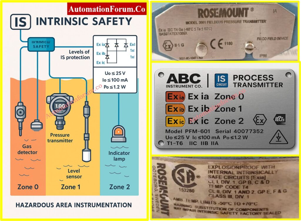
Intrinsic Safety (IS), which is shown as Ex i, is the most common way to protect instrumentation and control systems against explosions in hazardous locations. IS does not depend on containment like explosion-proof (Ex d) or purged/pressurized enclosures (Ex p). Instead, it stops ignition by making sure that the electrical and thermal energy in the circuit is lower than the minimum ignition energy of the gas or vapor that is potentially hazardous.
Principles of Energy Limitation in Hazardous Areas
In practice, this means limiting circuit voltage, current, capacitance, and inductance so that even under normal and fault conditions, the energy remains incapable of causing ignition. Typical IS limits for Group IIC gases such as hydrogen or acetylene are:
- Voltage (Uo): ≤ 25 V
- Current (Io): ≤ 100 mA
- Power (Po): ≤ 1.2 W
IEC 60079-11 Safety Levels
The protection levels defined in IEC 60079-11 are:
- Ex ia – withstands two simultaneous faults; highest level of safety.
- Ex ib – withstands one fault; medium level of safety.
- Ex ic – safe only in normal operation; basic safety level.
These correspond to hazardous area zones:
- Zone 0 (continuous hazard) → Ex ia.
- Zone 1 (likely hazard) → Ex ib.
- Zone 2 (rare hazard) → Ex ic.
By ensuring entity compatibility (Uo ≤ Ui, Io ≤ Ii, Po ≤ Pi, and cable capacitance/inductance ≤ certified values), intrinsic safety simplifies installation and permits live maintenance, while meeting ATEX, IECEx, and IEC 60079 standards.
ATEX vs IECEx Certification Guide: ATEX vs IECEx Certification: Complete Guide for Hazardous Area Instrumentation
Fault Tolerance and Zener Diodes in IS Barriers
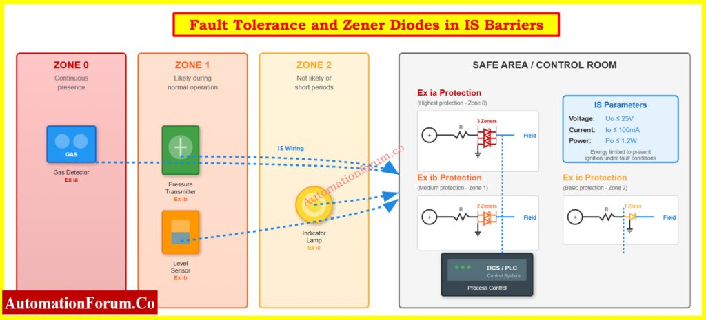
Fault tolerance is the most important part of intrinsic safety design. It makes sure that no unsafe energy gets to the dangerous location, even if the protecting parts fail.
Zener Diodes in IS Barriers
- Function: work by clamping overvoltage and sending surplus energy to the ground.
- Ratings: The breakdown voltage is usually between 6.8 and 28 V, while the power is between 1 and 5 W.
- Selection: Pick a clamp voltage that is a little higher than the standard loop voltage. For instance, a 26 V Zener protects a 24 V loop without causing problems with clamping.
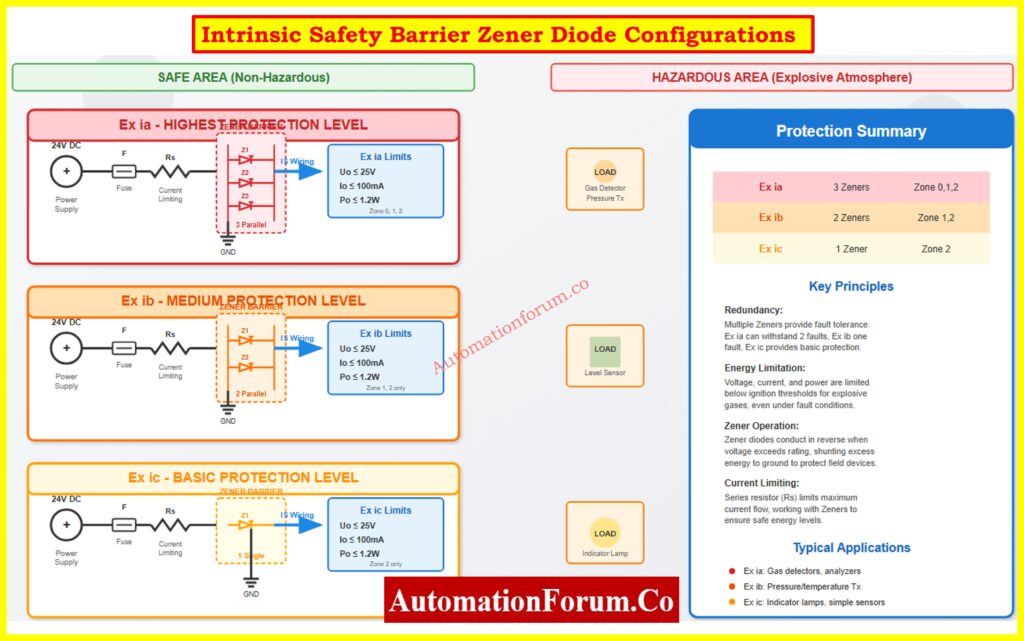
- Redundancy: Ex ia uses 3 diodes in parallel (2-fault tolerance), Ex ib uses 2, Ex ic uses 1.
Countable Faults
- No fault: Normal condition.
- Single fault: Failure of one protective component (e.g., diode short/open).
- Two faults: Simultaneous failure of two protective devices.
Ex ia must remain safe in all three conditions; Ex ib in the first two; Ex ic only in normal operation.
Temperature Derating of Zener Diodes
Zener diodes must be derated for ambient temperature. A 1W Zener may provide only 0.5 W at 60°C. This is very important to meet the temperature class (T1-T6) requirements for hazardous gases.
Example Circuit Calculation
Let’s say the barrier output is Uo = 25 V and Io = 100 mA.
- Po = Uo × Io = 25 × 0.1 = 2.5 W.
But allowable Po ≤ 1.2 W.
So, series resistors and fuses must keep the maximum power at 1.2 W.
This mechanism that limits energy makes sure that IS circuits can’t spark or heat up to the point where they can start a fire, even in the worst possible conditions.
Benefits of IS Instrumentation: Why Choose Intrinsic Safety (IS) for Hazardous Area Instrumentation?
Exia Protection – Highest Safety Level
Ex ia is the highest level of safety that comes from inside. To make sure there is redundancy, the protective barrier usually includes three Zener diodes in parallel, along with resistors and fuses. This setup can handle two faults, which means it can still work safely even if two protective elements fail. The main idea is:
“No ignition during normal operation or in the presence of two countable faults.”
The design follows Failure Mode and Effects Analysis (FMEA) from a circuit reliability point of view. This makes sure that every possible failure mode leads to a safe state. Parallel Zener diodes guarantee clamping action even if one or two diodes short or go open circuit.
Technical Specifications
- Diode configuration: 3 Zeners in parallel.
- Voltage (Uo): ≤ 25 V.
- Current (Io): ≤ 100 mA.
- Power (Po): ≤ 1.2 W.
- Fault Tolerance: Two faults.
- Entity Parameters (Group IIC): Co ≈ 83 nF, Lo ≈ 4 mH.
Entity Concept Example
Cable capacitance = 50 nF/km, length = 1.2 km → total capacitance = 60 nF.
The installation is safe because Co (83 nF) is greater than 60 nF.
Applications and Characteristics
- Hazardous Zones: Good for Zone 0, Zone 1, and Zone 2, where explosive atmospheres may be present all the time or most of the time.
- Process Criticality: This is the best choice for safety-critical uses like gas detection systems, tank level monitoring, or chemical dosing devices.
- Energy Limitation: Usually limited to 25 V, 100 mA, and 1.2 W at most when there is a defect.
- Installation Requirements: It is important to keep intrinsically safe circuits separate from non-IS wiring. This can be done with blue-colored insulation cables and separate terminal blocks.
- Certification: For example, “Ga” means that it is suitable for Zone 0, while “Ex ia IIC T4 Ga” means that it is. Safety parameters like Ui (input voltage), Ii (input current), and Pi (power) are included in the documentation.
- Real-world Applications: Gas analyzers, guided wave radar level transmitters, and emergency shutdown sensors are used in refineries.
IS vs Explosion-Proof Explained: Difference Between Intrinsically Safe and Explosion-Proof
Case Study – Offshore Oil & Gas Platform
There is always methane at the wellhead and vent zones (Zone 0) of offshore drilling rigs. Even if safety barriers fail, gas detecting systems must still be safe. Ex ia barriers with two-fault tolerance make sure that ignition energy never gets to the hazardous side. This lets personnel carry out live calibration and loop testing, which minimizes down on downtime.
So, Ex ia is the only option for Zone 0 and the best option for essential safety loops when risk tolerance is low.
Refer the below link for the Importance of NAMUR Sensors in Hazardous Areas
Exib Protection – Medium Safety Level
Ex ib protection is a medium level of safety and uses two Zener diodes in tandem. This setup makes sure that one fault won’t cause ignition, whether the system is working normally or if only one problem happens. But the system is not guaranteed to be safe if there are two failures.
Safety principle:
“No ignition during normal operation or with one fault present.”
Compared to Ex ia, redundancy is reduced, making Ex ib unsuitable for Zone 0 but fully acceptable for Zone 1.
Technical Specifications
- Diode configuration: 2 Zeners in parallel.
- Voltage (Uo): ≤ 25 V.
- Current (Io): ≤ 100 mA.
- Power (Po): ≤ 1.2 W.
- Fault Tolerance: One fault.
- Entity Parameters (Group IIC): Co ≈ 150 nF, Lo ≈ 8 mH.
Circuit Example
Pressure transmitter on a 24 VDC loop, cable inductance 1 mH/km × 2 km = 2 mH.
Since Lo = 8 mH, installation is safe.
Applications and Characteristics
- Hazardous Zones: Applicable to Zone 1 (likely explosive atmosphere during normal operations) and Zone 2.
- Process Criticality: Good for normal process instrumentation where there isn’t always an explosion present.
- Energy Limitation: The same electrical limits (<25 V, <100 mA), but less strict certification standards than Ex ia.
- Typical Instruments: Common tools include pressure transmitters, RTDs, thermocouples, control valve positioners, and flow transmitters.
- Installation Guidelines: Barriers must be properly grounded and kept separate from non-IS circuits. There are guidelines for routing cables that are safe in and of themselves.
- Cost-Benefit Analysis: Ex ib systems are usually cheaper than Ex ia systems because they have fewer protective parts and are easier to certify.
- Maintenance Considerations: Still needs to be checked on a regular basis, although the margins of reliability are less.
Ex ib is a good solution for Zone 1 classified areas such process units, offshore platforms, and petrochemical industries since it strikes a good compromise between safety and cost. It gives enough safety margins without the cost of Ex ia, unless criticality requires it.
Case Study – Chemical Processing Plant
During charging and venting, vapors are emitted from a reactor hall that is classed as Zone 1. Ex ib barriers connect temperature and pressure transmitters, which makes monitoring trustworthy. One-fault tolerance is plenty because explosive atmospheres aren’t always there. This method strikes a balance between safety and cost-effectiveness, making it possible to use field instrumentation widely without overengineering.
Ex ib is the most common standard for Zone 1 in process plants.
FISCO Model Explained: Fieldbus Intrinsically Safe Concept (FISCO) Model for Foundation Fieldbus H1 and Profibus PA
Exic Protection – Basic Safety Level
Ex ic is the lowest level of intrinsic safety. It merely uses one Zener diode to limit energy. It stops ignition only when the system is working normally because it doesn’t have any fault tolerance.
Safety principle:
“No ignition in normal operation only.”
Technical Specifications
- Diode configuration: Single Zener.
- Voltage (Uo): ≤ 25 V.
- Current (Io): ≤ 100 mA.
- Power (Po): ≤ 1.2 W.
- Fault Tolerance: None.
- Entity Parameters (Group IIC): Co ≈ 200 nF, Lo ≈ 10 mH.
Limitations
- Safe only in normal operation.
- No redundancy → unsafe for Zone 0 or Zone 1.
- Not acceptable for critical safety loops.
Applications and Characteristics
- Hazardous Zones: Only Zone 2 is dangerous because explosive atmospheres happen very seldom and only for brief periods of time (less than 10 hours a year).
- Process Criticality: Meant for monitoring that isn’t critical or for extra tasks.
- Circuit Simplicity: Needs very little protection circuitry, which makes it cheaper and easier to put into action.
- Installation Limits: Not allowed in Zone 0 or Zone 1 because there is no backup.
- Typical Applications: Indicator lamps, signal beacons, auxiliary sensors, or monitoring panels where ignition probability is extremely low.
Although cost-effective, Ex ic comes with significant limitations. Engineers must perform careful risk assessment to justify its selection. It is never recommended for process safety functions or critical measurement instruments. Instead, it serves best in secondary instrumentation systems located in marginal Zone 2 areas.
Case Study – Pharmaceutical Clean Room
In a clean room using ethanol-based solvents, small vapor releases create Zone 2 areas near filling equipment. Ex ic protection is acceptable for non-critical devices such as humidity sensors and indicator lamps. Since explosive atmospheres are rare and ventilation is strong, Ex ic provides an economical solution while meeting regulatory standards.
Ex ic is therefore a cost-effective option for low-risk Zone 2 installations.
IS Loop Failure Causes & Prevention: Top Causes of Intrinsically Safe (IS) Loop Failure and How to Avoid Them
Hazardous Area Zone Classification
Hazardous areas are classified by likelihood of explosive atmosphere presence:
- Zone 0: Continuous presence (>1000 hours/year). Example: inside storage tanks. Requires Ex ia (Ga).
- Zone 1: Likely presence during normal operation (10-1000 hours/year). Example: pump rooms, agitator heads. Requires Ex ib (Gb).
- Zone 2: Rare and short duration (<10 hours/year). Example: ventilated solvent storage. Allows Ex ic (Gc).
Gas Groups
- IIA – Propane class.
- IIB – Ethylene class.
- IIC – Hydrogen, acetylene (most stringent).
Temperature Classes
- T1-T6: Maximum allowable surface temperature.
- Example: T6 = 85°C (safe for diethyl ether).
Case Studies
- Mining (Zone 0): Because methane is always present, Ex ia gas detection loops are needed.
- Paint Spray Booth (Zone 1): Because there are vapors in the air while spraying, sensors and controllers need Ex ib.
- Ventilated Solvent Storage (Zone 2): Ex ic indication bulbs are enough because the risk is low.
So, the type of IS protection you choose depends on the zone classification.
IS vs Non-IS Cable Comparison: Difference Between Intrinsically Safe (IS) and Non-IS Cables
Comparative Analysis of IS Protection Levels
Parameter Comparison Table: Ex ia vs Ex ib vs Ex ic
This table provides engineers with a complete overview for decision-making, combining electrical limits, protective component count, installation requirements, maintenance schedules, cost considerations, and real-world applicability.
| Parameter | Ex ia | Ex ib | Ex ic |
| Zener Diodes | 3 (parallel) | 2 (parallel) | 1 |
| Fault Tolerance | 2 faults (highest) | 1 fault (medium) | 0 faults (normal operation only) |
| Maximum Voltage (Uo) | ≤ 25 V | ≤ 25 V | ≤ 25 V |
| Maximum Current (Io) | ≤ 100 mA | ≤ 100 mA | ≤ 100 mA |
| Maximum Power (Po) | ≤ 1.2 W | ≤ 1.2 W | ≤ 1.2 W |
| Circuit Capacitance (Co) | ~83 nF | ~150 nF | ~200 nF |
| Circuit Inductance (Lo) | ~4 mH | ~8 mH | ~10 mH |
| Hazardous Zones | 0, 1, 2 | 1, 2 | 2 only |
| Equipment Protection Level | Ga (very high safety) | Gb (high safety) | Gc (basic safety) |
| Cost Impact | Premium +20% | +10% | Baseline |
| Maintenance Frequency | Annual inspection | Annual inspection | Quarterly check |
| Typical Applications | Gas detectors, SIS loops, level sensors | Standard process transmitters, valves | Indicators, alarms, auxiliary devices |
| Installation Complexity | High (requires careful layout, segregation, grounding, blue IS cabling) | Medium (moderate segregation, barrier grounding) | Low (simplified circuit design, minimal segregation) |
| Reliability Factor | Very high (two-fault tolerance ensures safety under multiple failures) | High (single-fault tolerance, reliable under normal and one fault) | Moderate (safe only under normal operation) |
| Entity Parameters Compliance | Uo ≤ Ui, Io ≤ Ii, Po ≤ Pi, Co & Lo checked for cable lengths | Uo ≤ Ui, Io ≤ Ii, Po ≤ Pi, Co & Lo verified | Uo ≤ Ui, Io ≤ Ii, Po ≤ Pi, Co & Lo verified |
| Example Real-World Case | Offshore oil & gas methane detection, critical SIS loops | Chemical plant pressure/temperature transmitters | Pharmaceutical clean room indicators, mining auxiliary alarms |
Real-World Applications by Zone
- Ex ia is mandatory for Zone 0 or any continuously hazardous area. It provides maximum redundancy and reliability.
- Ex ib is good for Zone 1 because it strikes a good balance between safety and cost. For explosive atmospheres that happen only sometimes, single-fault tolerance is enough.
- Ex ic only works in Zone 2, which is great for low-risk, non-critical circuits when saving money is the most important thing.
Refer the below link for the Intrinsic Safe Calculation for Instrumentation Design Engineers
Practical Selection Criteria for IS Protection
To choose the right level of intrinsic safety protection, you need a structured decision-making framework:
- Risk Assessment: Look at how likely it is that a fire will start in the specific dangerous area and what will happen if it does.
- Process Criticality: Use Ex ia for important shutdowns or monitoring, Ex ib for regular process measurements, and Ex ic for monitoring that isn’t very important.
- Cost-Benefit Analysis: Balancing safety with cost higher hazardous zones justify higher investment.
- Follow the rules: Make sure you follow IEC 60079-11, ATEX, and IECEx.
- Future Growth: Think about how easy it is to scale up and whether the instrumentation would need to work in Zone 0 later on.
- Maintenance Capabilities: Choose a level of protection based on the inspection resources you have.
- Vendor Availability: Make sure that parts and spares are easy to get and come with the right certifications.
This strategy makes sure that a logical, standards-compliant choice is made that fits within both budget and process safety limits.
IS Cable Checklist for ATEX Zones: Intrinsically Safe Cables for ATEX Zones – Complete Checklist for EPC Engineers
Installation and Maintenance Best Practices
Here are some best practices for setting up an IS:
- Earthing/Grounding: Make sure that the Zener barriers are properly bonded so that they may still redirect energy.
- Choosing Cables: For IS circuits, use blue-insulated cables that are separate from non-IS cabling.
- Segregation: To avoid induced faults, route IS and non-IS circuits separately.
- Documentation: Keep all loop designs, barrier certificates, and safety specifications up to date.
- Inspection: Follow the IEC 60079-17 rules for regular inspections.
- Testing: Before placing the system into use, check the loop’s integrity, insulation resistance, and barrier grounding.
Strict adherence makes sure that intrinsic safety integrity is maintained throughout the life of the device.
Intrinsic Safety has a tiered system for protecting dangerous areas that strikes a balance between safety, dependability, and cost. Ex ia makes sure that Zone 0 can survive two faults, Ex ib makes sure that Zone 1 can survive one fault, and Ex ic makes sure that Zone 2 is safe. Engineers make IS loops that meet IEC 60079-11, ATEX, and IECEx standards by following the rules for voltage, current, power, and entity parameters. This makes sure that the installations are safe,
FAQ on Understanding Exia, Exib, and Exic
1. What is the difference between Ex ia, Ex ib, and Ex ic?
- Ex ia: The highest level of safety; can handle two faults at the same time; works in Zone 0, 1, and 2.
- Ex ib: Medium safety; can handle one mistake; works in Zones 1 and 2.
- Ex ic: Basic safety; no fault tolerance; suitable for Zone 2 only.
Key difference: Fault tolerance, applicable hazardous zones, and reliability.
2. What is Ex ic?
Ex ic is the basic level of intrinsic safety protection.It only works safely when everything is working normally, and it doesn’t have any fault tolerance. It’s utilized in Zone 2, where explosive atmospheres are infrequent and only last a short time. Indicator lights, alarms, and extra gadgets are some of the most common uses.
3. What is Ex-ia and Ex-ib?
- Ex ia: Intrinsically safe equipment that remains safe with two faults; can be used in Zone 0.
- Ex ib: Intrinsically safe equipment that remains safe with one fault; suitable for Zone 1.
IEC 60079-11 defines both as intrinsic safety protection levels. They differ in how much fault tolerance they have and where they can be installed.
4. What is the difference between intrinsically safe and ATEX?
- Intrinsically Safe (IS/Ex i): A way to protect circuits by limiting the flow of energy so that explosive gases or dust don’t catch fire.
- ATEX is a European regulatory directive (2014/34/EU) that covers equipment for hazardous circumstances. It includes IS, flameproof (Ex d), and other ways to safeguard.
The main difference is that IS is a technological protective approach and ATEX is a framework for compliance and certification.
5. What is the full form of ATEX?
ATEX means:
- AT = ATmospheres
- EX = Explosives
It is a European rule that controls equipment that is meant to be used in places where there are explosions.
6. How to identify intrinsically safe equipment?
Look for:
- Markings on the tools, like Ex ia IIC T4 Ga and Ex ib IIB T3 Gb.
- Manufacturer documentation: Certificates of conformity (IECEx, ATEX).
- Blue IS wiring and segregated terminals in installation.
- Low voltage/current limits (≤25 V, ≤100 mA, ≤1.2 W typical for IIC gases).
IS Instrument Installation Checklist: Installation Checklist for Intrinsically Safe Instrument (Apparatus)
Test your expertise on Intrinsic Safety Instrumentation Circuits in Oil & Gas Process Industries
Refer the below link to test your understanding on on Intrinsic Safety Instrumentation Circuits in Oil & Gas Process Industries with our Advanced Quiz
 for hazardous areas. Compare protection levels, zones, Zener barriers, and ATEX/IECEx compliance.)