
- What Is an ESD Signal in an Emergency Shutdown System?
- Why Is ESD Signal Selection Important in ESD System Design?
- How Are ESD Signals Selected During Basic Design?
- What Are the Main Sources of ESD Signals?
- How Is the Required ESD Level Determined?
- How Are ESD Signals Verified During Detail Design?
- ESD Signals and SIL Rated SIFs
- Which ESD Signals Are Not Necessarily SIL Rated SIFs?
- How Does the Cause and Effect Matrix Help Select ESD Signals?
- How Are Package Vendor Trips Connected to the ESD System?
- What are the Common ESD Signal Selection Mistakes?
- What Is the Practical ESD Signal Selection Workflow?
- ESD Signal Selection Checklist for Instrumentation Engineers
- Practical ESD Signal Selection Example for a Process Compressor
- How Can ESD Signal Selection Be Improved During Engineering Projects?
- Key Takeaway About ESD Signal Selection
- Frequently Asked Questions About ESD Protection
- Frequently Asked Questions About ESD Signal Selection
Selecting the right signals for an Emergency Shutdown System is one of the most important activities in instrumentation and control engineering. A common question during design reviews is simple: Which signals should be connected to the ESD system?
The answer is not obtained by looking at the SIL study alone. Proper ESD signal selection requires engineers to combine process safety studies, the Shutdown Philosophy, Cause and Effect Matrix, SIL and LOPA results, package requirements, external interfaces, client specifications and engineering judgment. The attached engineering reference follows the same approach by separating candidate signal identification during Basic Design from detailed verification before final ESD I O allocation.
For an instrumentation engineer, the objective is not to collect as many shutdown signals as possible. The objective is to identify signals that have a clearly defined purpose, assign the appropriate ESD level and ensure that every selected signal has a traceable engineering basis.
Poor ESD signal selection can create unnecessary shutdowns, missing protection functions, incorrect logic and difficult commissioning. Good selection creates a shutdown system that is understandable, traceable and aligned with the process safety design.
Master Critical Shutdown Strategies Every Process Engineer Should Know: ESD vs PSD: Difference Between Emergency Shutdown System and Process Shutdown System
What Is an ESD Signal in an Emergency Shutdown System?
What Is an ESD Input Signal?
An ESD signal is a signal that is used by an Emergency Shutdown System to initiate a predefined protective or shutdown action.
What Is an ESD Output Signal?
An ESD output may stop a pump, trip a compressor, close an isolation valve, shut down a package, initiate unit shutdown or initiate a wider plant shutdown.
ESD Signal vs SIL Rated Safety Instrumented Function
It is important to understand that an ESD signal is not automatically a SIL rated Safety Instrumented Function. An ESD system can contain signals required for equipment protection, operational shutdown, package protection, Fire and Gas interfaces, utility failure, regulatory requirements or client specific requirements.
A SIF has a specific safety function identified through the applicable safety lifecycle and normally has a required SIL determined through an appropriate assessment. The SIS provides the instrumentation and logic necessary to implement such safety functions according to the approved Safety Requirements Specification and applicable standards.
Uncover The Safety Principles Behind Reliable Process Protection: Process Safety vs Functional Safety: Key Differences, SIS, SIF, SIL & IEC 61511 Guide
Why Is ESD Signal Selection Important in ESD System Design?
Selecting the Correct ESD Shutdown Action
The selected ESD signals determine what conditions the ESD system can recognize and what protective actions it can initiate.
A properly developed ESD system helps ensure that the correct shutdown action occurs at the correct ESD level. It also helps protect personnel, equipment and the process while reducing the possibility of escalation.
Maintaining ESD I O List Traceability and Improving ESD Commissioning and Maintenance
The quality of the ESD I O list also affects commissioning and maintenance. Every input should have a clear reason for being present. Every output should have a defined action. The relationship between the initiating condition, logic, final action and field device should be traceable.
One common engineering mistake is to generate the ESD I O list from only one document. For example, using only the SIL study can result in important non SIL shutdown interfaces being missed. Conversely, adding every package trip without checking the Cause and Effect Matrix can create unnecessary or duplicate shutdown functions.
Refer the below link for the Advanced Safety Instrumented System (SIS) Inspection Checklist for IEC 61511 Compliance
How Are ESD Signals Selected During Basic Design?
During Basic Design, the engineer develops an initial list of candidate ESD signals. At this stage, the objective is to identify possible shutdown requirements rather than immediately freeze the final ESD I O list.
Review the Process Description
The Process Description explains how the facility operates and what abnormal conditions can affect the process.
Engineers can use it to understand major equipment, process flow, operating conditions and potential consequences of abnormal operation. This provides the initial process context for identifying shutdown requirements.
Review the PFD and P and ID
The PFD and P and ID provide the physical and process representation needed for ESD engineering.
The engineer reviews equipment, process lines, valves, pressure protection devices, utilities, isolation points and important process measurements. This review helps identify where shutdown actions may be required.
Review the HAZOP Report
The HAZOP report is a major source of candidate shutdown requirements.
HAZOP recommendations may identify situations such as high pressure, low flow, high temperature, loss of cooling or other abnormal conditions where an automatic protective action may be required.
However, a HAZOP recommendation should not automatically become an ESD input. It must be evaluated against the final engineering philosophy and Cause and Effect requirements.
Prepare For SIS Interviews With Practical Engineering Questions: Safety Instrumented System(SIS) Interview Questions and Answers
Review the Cause and Effect Matrix
The Cause and Effect Matrix defines relationships between initiating causes and required actions.
It is one of the most important documents for confirming whether a candidate signal actually results in an ESD action.
Review the Shutdown Philosophy
The Shutdown Philosophy defines how shutdown levels are organized and how the plant should respond to abnormal conditions.
This document is particularly important when determining whether a signal should initiate plant shutdown, unit shutdown, equipment shutdown or a local equipment action.
Review the Fire and Gas Philosophy
The Fire and Gas Philosophy defines how fire and gas events interact with the ESD system.
It can identify shutdown commands, equipment isolation requirements and interfaces between Fire and Gas and the ESD system.
Review the Interface Philosophy
The Interface Philosophy is essential where ESD signals cross system or package boundaries.
It helps define responsibilities between the ESD system, package systems, electrical systems, HVAC systems, Fire and Gas systems and upstream or downstream facilities.
Review Package Vendor Documents
Package equipment frequently generates important trip signals. Compressors, turbines, boilers, fired equipment and rotating machinery can have dedicated protection systems.
Vendor trip lists, logic diagrams and interface documents must therefore be reviewed before finalizing the ESD I O list.
Review Client and Regulatory Requirements
Client specifications and regulatory requirements may introduce shutdown functions that are not directly identified through the SIL study.
These requirements should be reviewed early because they can influence ESD architecture, interfaces, hardwired requirements and commissioning activities.
Avoid Costly Safety Design Failures Before They Reach Commissioning: Top Critical Mistakes in Safety Instrumented System Design as per ISA 84 Standard and How to Avoid Them
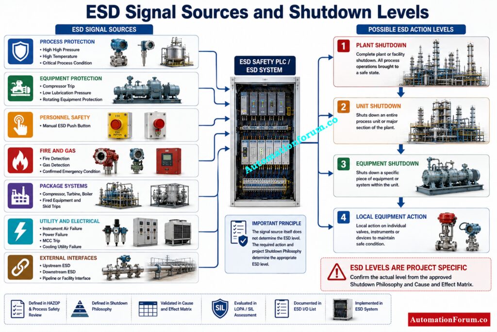
What Are the Main Sources of ESD Signals?
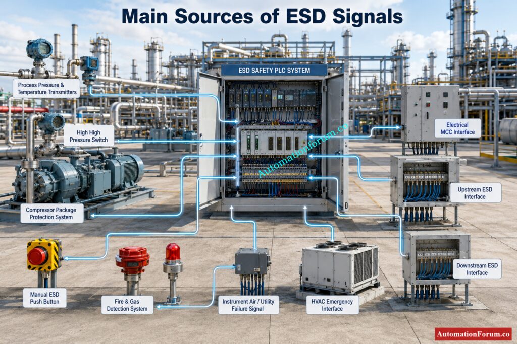
Potential ESD signals can originate from several engineering areas.
- Process protection may include high high pressure, high temperature or another process condition requiring shutdown.
- Equipment protection may include compressor protection, low lubrication pressure or rotating equipment trips.
- Environmental protection may involve shutdown actions intended to prevent process releases or escalation.
- Fire and Gas systems may generate shutdown commands following confirmed fire or gas conditions.
- Package systems may provide dedicated equipment trips that must be transferred to the plant ESD system.
- Utility and electrical systems may provide signals associated with loss of instrument air, power, cooling water or electrical equipment protection.
- External systems may provide upstream ESD, downstream ESD, pipeline trip or other facility interface commands.
The important point is that the source alone does not determine whether the signal belongs in the ESD system. Its required action and engineering purpose must also be established.
Discover How Transmitter Redundancy Prevents Dangerous Process Failures: Redundant Transmitters Explained: Reliability, Voting Logic and SIL for Instrumentation Engineers
How Is the Required ESD Level Determined?
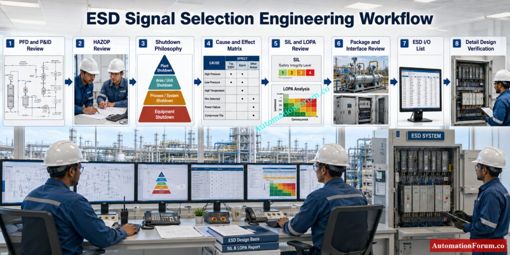
After identifying candidate signals, engineers must determine the appropriate ESD level.
- Typical project dependent levels may include plant shutdown, unit shutdown, equipment shutdown and local equipment action.
- The actual naming and numbering can vary between projects. One project may use ESD 0 for plant shutdown and another may use a different numbering convention.
- The correct level should therefore be established from the approved Shutdown Philosophy and Cause and Effect Matrix rather than assumed from generic industry terminology.
For example, high pressure on one process vessel may require equipment isolation, while a similar condition on another system may require unit shutdown because of the consequences of continued operation.
Refer the below link for the Designing 2 out of 3 Voting Logic in Control Systems
How Are ESD Signals Verified During Detail Design?
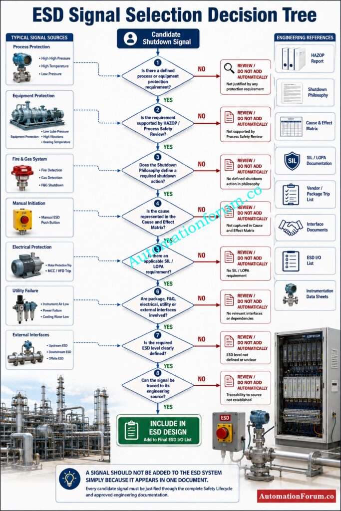
During Detail Design, every candidate signal should be challenged before it becomes part of the final ESD I O list.
- The engineer should ask whether the signal is defined in the Cause and Effect Matrix and whether there is a corresponding HAZOP recommendation. The engineer should also check whether it is identified as a SIF through the approved SIL study or LOPA.
- Package requirements must be verified against vendor documentation. Client specifications must also be checked.
- The engineer should confirm whether a hardwired trip is required, whether the signal is needed for operation or maintenance and whether it originates from an external system.
- The Interface Philosophy and vendor interface documents should be reviewed to avoid duplicate or conflicting shutdown commands.
- Finally, the engineer must determine the ESD level associated with the signal.
This verification process prevents a candidate signal from entering the ESD I O list simply because it appears in one document.
Understand How Emergency Valves Protect Critical Process Equipment: What is an Emergency Block valve and How does it work
ESD Signals and SIL Rated SIFs
One of the most common misconceptions in ESD engineering is that every ESD signal must be part of a SIL rated SIF.
That is not correct.
A SIF is a defined safety function intended to achieve a specific risk reduction objective. Its required SIL is determined through the applicable safety lifecycle and approved assessment.
A SIS is the system used to implement safety instrumented functions.
An ESD signal is simply an initiating or interface signal associated with an ESD action.
The final classification must always follow the approved project safety documentation.
Explore Advanced Pressure Protection Before Dangerous Overpressure Escalates: How does the HIPPS system work in the Oil and gas Industry?
Which ESD Signals Are Not Necessarily SIL Rated SIFs?
- A Fire and Gas shutdown command can initiate predefined process isolation following a fire or gas event.
- A compressor package trip can protect the package against a condition detected by its dedicated protection system.
- A utility failure signal can initiate shutdown when loss of an essential utility makes continued operation unacceptable.
- HVAC shutdown commands can be required during specific emergency conditions to control air movement.
- Electrical or MCC interfaces can provide motor protection or electrical trip information.
- Upstream and downstream ESD commands can coordinate shutdown between interconnected facilities.
- Pipeline trip signals can isolate process systems when required by the overall facility interface philosophy.
- Operational shutdown commands may also be connected to the ESD system when required by the approved design.
- These examples demonstrate why the ESD I O list should not be created from the SIL study alone.
Choose The Correct Valve Failure Strategy With Confidence: ESDV vs EBDV – Fail Close vs Fail Open
How Does the Cause and Effect Matrix Help Select ESD Signals?
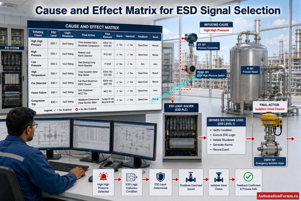
- The Cause and Effect Matrix provides the engineering relationship between an initiating cause and the required final action.
- For each candidate ESD signal, the engineer should identify the cause, applicable ESD level, logic response, final action, final element, alarm, interlock, feedback and reset requirement.
- Consider a high high pressure condition. The engineer must determine whether the condition should generate an alarm only, initiate equipment shutdown, isolate a process section or initiate a larger shutdown.
- This is where the Cause and Effect Matrix becomes more useful than a simple signal list. It explains what the signal is expected to do.
- The ESD I O list should therefore remain consistent with the Cause and Effect Matrix throughout design development.
Know Exactly When Shutdown Protection Should Be Applied: ESD vs SIS Difference When to Use Each and Practical Engineering Guide
How Are Package Vendor Trips Connected to the ESD System?
- Package systems are a frequent source of ESD interface complexity.
- Compressors, turbines, boilers, fired equipment, rotating machinery and packaged skids may have their own protection logic.
- Electrical systems, MCCs, HVAC systems and Fire and Gas systems also create interfaces.
- Before adding a vendor trip to the ESD system, the engineer should review the vendor logic diagram, trip list, interface document and shutdown requirements.
- The same principle applies to upstream and downstream facilities. A shutdown command crossing a battery limit must have a clearly defined source, destination, action and reset philosophy.
Build Strong Functional Safety Knowledge From Essential Fundamentals: What is SIS, SIF and SIL? An In-Depth Guide to Functional Safety in Process Industries
What are the Common ESD Signal Selection Mistakes?
- A common mistake is selecting ESD signals only from the SIL study. This can miss operational, package and interface requirements.
- Another mistake is adding every package trip without checking the Cause and Effect Matrix. This can produce unnecessary shutdowns and duplicate logic.
- Ignoring the Shutdown Philosophy can result in incorrect ESD levels.
- Missing upstream or downstream interfaces can leave gaps in coordinated shutdown.
- Failing to verify client requirements can create late design changes.
- Poor traceability between HAZOP, Cause and Effect and the ESD I O list makes commissioning difficult because engineers cannot easily establish why a signal exists.
Calculate Safety Performance Before Approving Your Critical SIF: SIF PFDavg / SIL Verification – Complete Guide + Online Calculator (IEC 61508 / 61511)
What Is the Practical ESD Signal Selection Workflow?
A practical workflow starts with PFD and P and ID review, followed by HAZOP review and Shutdown Philosophy review.
The engineering team then determines the required ESD level and develops or updates the Cause and Effect Matrix.
SIL and LOPA results are reviewed to identify applicable SIF requirements. Package and external interfaces are then coordinated.
The candidate signals are converted into the ESD I O list and verified during Detail Design.
The process is iterative. A change to the Cause and Effect Matrix, package documentation or interface philosophy can require changes to the ESD I O list and logic.
Handle Testing Delays Without Compromising Functional Safety Requirements: Testing and Repair Deferral – IEC Guidelines, Procedure, and Best Practices
ESD Signal Selection Checklist for Instrumentation Engineers
Before finalizing an ESD I O list, verify the following:
- Is there a clear process requirement?
- Has the HAZOP recommendation been reviewed?
- Does the Shutdown Philosophy support the action?
- Is the signal represented in the Cause and Effect Matrix?
- Has SIL and LOPA information been reviewed?
- Has the package vendor requirement been verified?
- Has the client specification been checked?
- Have Fire and Gas interfaces been reviewed?
- Have electrical and MCC interfaces been checked?
- Have HVAC and utility interfaces been checked?
- Have upstream and downstream interfaces been confirmed?
- Is a hardwired trip required?
- Is the correct ESD level assigned?
- Can the signal be traced back to its engineering source?
- Can the signal be tested during ESD commissioning?
Download Essential Safety Terminology Every Engineer Should Master: Functional Safety Terminology – Excel Download for Industrial Automation
Practical ESD Signal Selection Example for a Process Compressor
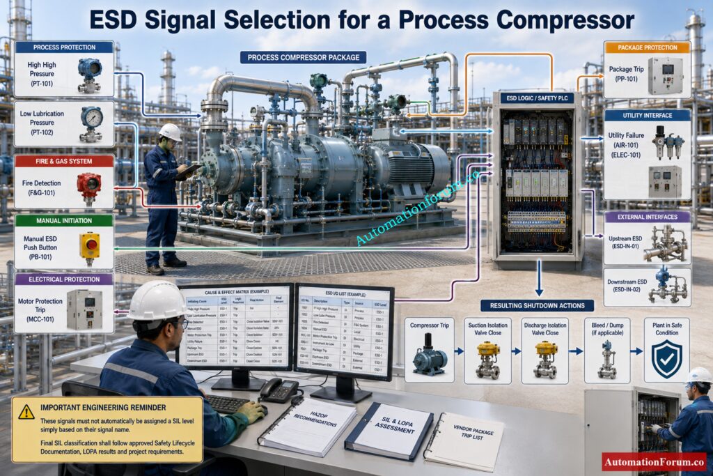
Consider a process compressor with several potential shutdown signals.
- A high pressure signal may be associated with a process protection function. A high high pressure condition may require a defined shutdown action established through the Cause and Effect Matrix and safety assessment.
- Low lubrication pressure may primarily represent equipment protection and may originate from the compressor package.
- Fire detection may generate a shutdown command through the Fire and Gas interface.
- A motor protection trip may originate from the electrical system or MCC.
- Utility failure may require compressor shutdown because continued operation is not acceptable.
- A package trip may be required to protect the compressor based on vendor requirements.
- Upstream and downstream ESD signals may coordinate shutdown between connected facilities.
- None of these signals should be assigned a SIL level simply from the signal name. The final determination must come from the approved safety lifecycle documentation and project requirements.
Identify Critical Shutdown Signals Before Designing Your Protection System: Signals for Emergency Valve Shutdown in Critical Processes
How Can ESD Signal Selection Be Improved During Engineering Projects?
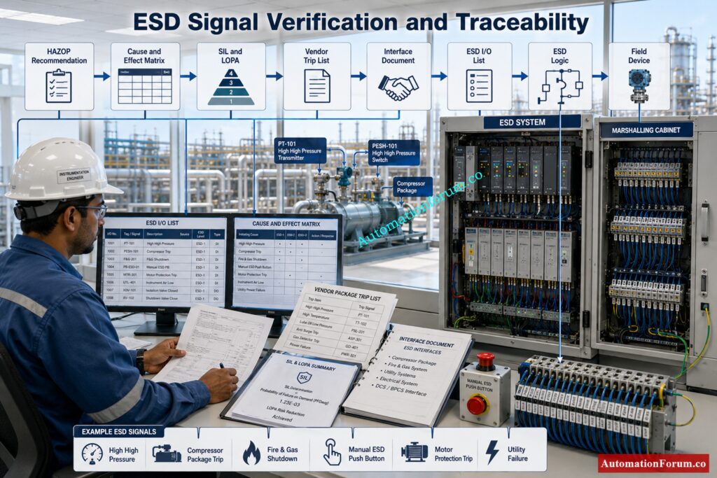
- The best results come when process safety, operations, instrumentation, control, electrical, mechanical, package and commissioning engineers become involved early.
- The Cause and Effect Matrix should be treated as a controlled engineering document and updated whenever the process design or shutdown philosophy changes.
- Interface coordination should start before detailed I O development. Vendor documents should be reviewed early rather than during commissioning.
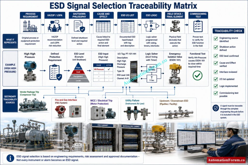
- Most importantly, maintain traceability from the HAZOP recommendation to the Cause and Effect Matrix, ESD I O list, implemented logic and commissioning test documentation.
This approach gives the engineering team confidence that every important shutdown function has a clear basis and every selected signal has a defined purpose.
Challenge Your SIS Knowledge With Real Engineering Questions: Test Your Expertise in Safety Instrumented Systems (SIS): Knowledge Quiz
Key Takeaway About ESD Signal Selection
The ESD I O list should not be generated from the SIL study alone. It should be developed by integrating process safety studies, Shutdown Philosophy, Cause and Effect Matrix, SIL and LOPA results, interface engineering, vendor documentation, client requirements, regulatory requirements and practical engineering judgment.
A well designed ESD system is the result of connecting these engineering inputs into one traceable design process. The strongest ESD engineering practice is therefore not to select every possible shutdown signal, but to select the right signal, for the right action, at the right ESD level, with a clearly documented engineering reason. This integrated approach is also consistent with the engineering workflow represented in the supplied reference, from Basic Design through Detail Design and iterative review.
Master Solenoid Valve Configurations For Reliable Shutdown Applications: Understanding 2 out of 2 SOV: Working & Configuration
Frequently Asked Questions About ESD Protection
How to choose ESD protection?
ESD protection is chosen based on the required shutdown function, process risk, ESD level, Cause and Effect Matrix and applicable project requirements.
The selected protection should provide the required response without creating unnecessary or nuisance shutdowns.
What is ESD 1 and ESD 2?
ESD 1 and ESD 2 are project specific shutdown levels, commonly representing different scopes such as unit shutdown and equipment shutdown.
Their exact meaning must be confirmed from the project Shutdown Philosophy because numbering varies between projects.
How are ESD items identified?
ESD items are identified by reviewing the P and ID, HAZOP, Shutdown Philosophy, Cause and Effect Matrix, SIL and LOPA studies, vendor documents and interface requirements.
Each item should then be verified for its shutdown action, ESD level and traceability before inclusion in the ESD I O list.
What is the difference between ESD and PSD?
ESD means Emergency Shutdown and generally provides protective shutdown during hazardous or emergency conditions.
PSD means Process Shutdown and is generally associated with controlled process or equipment shutdown, with the exact distinction defined by project philosophy.
What are the two main types of ESD damage?
The two common categories are catastrophic damage, where the component fails immediately, and latent damage, where the component remains functional but its reliability is reduced.
Latent ESD damage can become apparent later during equipment operation.
Test Your ESD Knowledge Before Facing Real Plant Scenarios: ESD Control System Basics Quiz for Process Industries
Frequently Asked Questions About ESD Signal Selection
How are ESD signals selected?
ESD signals are selected by reviewing process safety studies, Shutdown Philosophy, Cause and Effect Matrix, SIL and LOPA results, vendor documents and interface requirements.
The final selection must confirm the required shutdown action and ESD level before inclusion in the ESD I O list.
Is every ESD signal a SIL rated SIF?
No. An ESD system can contain operational, equipment protection, package, utility and interface signals that are not necessarily assigned a SIL level.
Only functions identified through the applicable safety lifecycle should be treated as SIL rated SIFs.
What documents are used for ESD signal selection?
Important documents include PFD and P and ID, HAZOP, Shutdown Philosophy, Cause and Effect Matrix, SIL study, LOPA, vendor documents and client specifications.
Interface philosophy, Fire and Gas documentation and regulatory requirements may also influence the final ESD I O list.
Why is the Cause and Effect Matrix important for ESD design?
The Cause and Effect Matrix establishes the relationship between the initiating signal, ESD level, logic and required final action.
It allows engineers to verify that each selected ESD signal has a clearly defined shutdown purpose.
Should the ESD I O list be prepared from the SIL study?
No. The ESD I O list should integrate SIL and LOPA results with process safety studies, Cause and Effect, Shutdown Philosophy and vendor requirements.
External interfaces, client requirements and engineering judgment must also be considered before the list is finalized.
Refer the below link for the Designing 2 out of 4 Voting Logic in Control Systems
