- Why Thermowells Are Essential
- Basic Components of a Thermowell
- Types of Thermowells
- Step-by-Step Thermowell Selection Procedure
- Additional Design Considerations
- Thermowell Sizing Examples
- Thermowell Selection Checklist (Excel Download)
- Frequently Asked Questions (FAQ) on Thermowell Selection
- Test your Knowledge on RTD and Thermocouple Selection for Instrumentation Design Engineers
The American Society for Testing and Materials (ASTM) says that a thermowell is “a closed end re-entrant tube designed for insertion of a temperature sensing element and provided with means for a pressure-tight attachment to a vessel.”
Thermowells are basically protective cases that hold temperature sensors like thermocouples, RTDs, or bimetallic thermometers. They are permanently installed in pipelines, tanks, or vessels so that sensors can be replaced, calibrated, or serviced without stopping the process or placing operators in hazards.
Choosing the right thermowell is an important design job for EPC engineers, instrumentation experts, and maintenance teams. If you choose the wrong thermowell, you could get wrong data, a sensor that doesn’t work, or even a mechanical breakdown that is really bad when there is pressure and vibration. This article gives you a step-by-step way to choose, using ASTM terminology, ASME PTC 19.3 criteria, and the best practices in the field.
Why Thermowells Are Essential
Thermowells do three jobs when it comes to measuring temperature in an industrial environment:
- Protection: They protect fragile sensors against corrosion, erosion, pressure, and fast-moving fluids.
- Isolation: They create a physical barrier that lets sensors be removed or calibrated without stopping the process.
- Containment: When designed correctly, thermowells assist keep the process safe and stop dangerous or high-pressure fluids from leaking.
Without thermowells, temperature sensors would be directly exposed to process conditions, which would cause them to wear out quickly, pose safety issues, and need to be repaired often.
Basic Components of a Thermowell
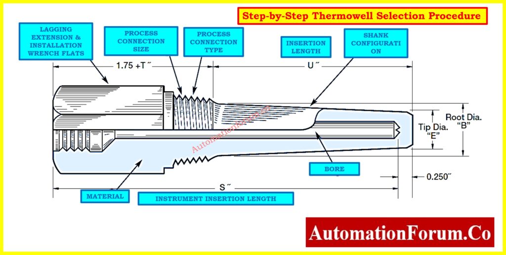
Every thermowell has important dimensions and features that affect how well it works (see Figure – Thermowell Parts).
- Bore Diameter (B): The inside diameter that was bored to fit the sensor probe. For ¼″ RTDs, the most common size is 0.260″, while for ⅜″ thermometer bulbs, it is 0.385″.
- Bore Depth (S): The total depth that the probe can go into.
- Insertion Length (U): This is also known as immersion length. It is the distance from the process connection to the end of the thermowell.
- Lagging Extension (T): Extra length above the process connection to make room for insulation or jackets.
- Extension Length (E): A longer length that moves the connecting head away from the heated surface.
- Shank Construction: The shape of the stem that is submerged—straight, stepped, or tapered.
- Base Diameter (Q): The thickest point on the outside of the shank.
- Tip Diameter (V): The diameter of the thermowell tip’s outside edge.
- Tip Thickness (E): The thickness of the closed end that keeps the process and the sensor tip apart.
- Process Connections: The way the thermowell connects to piping or vessels depends on whether it is threaded, flanged, or welded.
Types of Thermowells
Threaded Thermowells
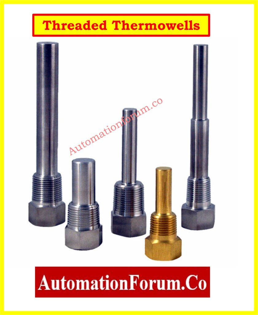
- inserted straight into smaller pipes with screws.
- Affordable and adaptable, but not the best for high-pressure or corrosive tasks.
Flanged Thermowells

- fitted with DIN or ANSI standard flanges.
- Ideal for processes involving high pressure and temperature.
- Simple to replace and remove.
Weld-In Thermowells
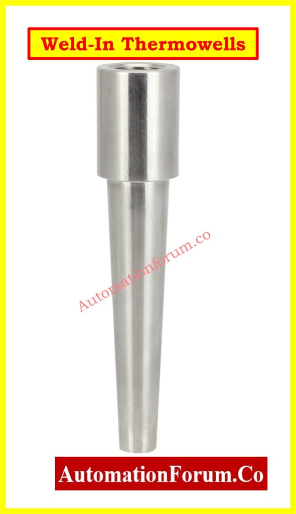
- permanently welded to vessels or process pipes.
- Robust and impervious to leaks, but replacement necessitates cutting and welding.
Check Thermowell Insertion & Immersion Length: Thermowell Insertion and Immersion Length
Socket-Weld and Sanitary Types

- utilized in hygienic or space-constrained settings.
Get Thermocouple Commissioning Checklist: Thermocouple Commissioning Checklist
Step-by-Step Thermowell Selection Procedure
When choosing a thermowell, measuring performance and mechanical integrity must be taken into account. The methodical process that follows guarantees precise and secure selection.
1. Define Process Connection Size and Type
Finding out how the thermowell will connect to the process machinery is the first step.
- Threaded (NPT): Frequently used in utility services; simple to set up.
- Flanged: Complies with the face type (raised, flat, or ring-joint) and piping flange rating (150#, 300#, etc.).
- Weld-In: Selected for long-term installations when preventing leaks is essential.
- Socket-Weld: Strong and small, socket-weld pipes are ideal for high-pressure applications.
- Sanitary Clamp: Food, beverage, and pharmaceutical systems all need sanitary clamps.
Get RTD Commissioning Checklist: RTD Commissioning Checklist
2. Select Insertion Length (U)
The U-dimension, also known as the insertion length, indicates how far the thermowell penetrates the process. This element is essential for mechanical stability as well as measuring accuracy.
- In Pipelines: To obtain a representative fluid temperature in pipelines, the thermowell tip should preferably touch the pipe’s centerline. The insertion depth should, at the very least, be at least one-third of the internal diameter of the pipe.
- In Tanks and Vessels: In tanks and vessels, 6 to 12 inches of penetration depth is usually adequate. Baffles, agitators, and other interior features should not be interfered with during placement.
- Standard Lengths: Depending on the needs of the process, thermowells can be inserted into the following standard lengths: 2.5, 4.5, 7.5, 10.5, 13.5, 16.5, and longer.
Design Note: AWhile an excessively long thermowell may experience vibration, resonance, and even mechanical failure, a thermowell that is too short may result in inadequate heat transfer and erroneous temperature readings. Always check the insertion depth against the relevant standards and process circumstances.
Discover Types of Thermowells: Thermowells & types of thermowells
3. Determine Lagging Extension (T)
If there are jackets or insulation, lagging extension is necessary.
- Standard values: 2″ or 3″.
- Customized to match insulation thickness.
- For simpler access, make sure the sensor head is outside the insulation.
4. Decide on Extension Length (E)
The sensor connection head is moved away from hot process surfaces by the extension length.
- Standard values: 3″ or 6″.
- Beneficial for high-temperature applications like as furnaces or steam pipes.
- Gives maintenance workers a safer working distance.
5. Match Sensor Length (X)
The temperature probe’s complete engagement with the thermowell is guaranteed by the sensor length, also known as the X-dimension. The sensor tip needs to be firmly in touch with the thermowell bore’s bottom in order to measure accurately. Slow response times and measurement mistakes might result from heat resistance introduced by any space between the sensor and the bore tip.
Simple calculations that change based on the type of process connection are used to determine the necessary sensor length:
- Threaded / Socket-Weld Thermowells:
X=U+T+E+1.5″ - Flanged Thermowells:
X=U+T+E+2.0″
Example:
If the insertion length (U) is 7.5″, lagging extension (T) is 3″, and extension length (E) is 0, for a threaded thermowell:
X=7.5+3+0+1.5=12″
Thus, a 12″ sensor probe is required to ensure proper contact with the bore tip.
Read Temperature Transmitter Datasheet Guide: How to Read a Datasheet of a Temperature Transmitter ?
6. Choose Bore Diameter
The bore diameter is the size of the hole within the thermowell where the sensor probe goes. Getting the right size for the bore is important for both accuracy and ease of installation.
- 0.260″ bore: The 0.260″ bore is made for ¼” RTD or thermocouple probes. This is a typical choice for precise instrumentation.
- 0.385″ bore: Works with ⅜″ thermometer stems or bulbs, which are usually used in bimetallic thermometers.
Engineering Note: To reduce air gaps, which function as insulators and slow down heat response, the space between the sensor and the bore should be as narrow as feasible. But there needs to be enough space for the probe to be put in and taken out easily.
Learn How to Specify a Thermowell: How to specify a thermowell?
7. Select Shank Style
The shape of the stem has a direct effect on strength and response time.
- Straight: Same diameter all the way around; basic design for low-pressure use.
- Stepped: The smaller tip makes the response time better, but it also makes the mechanical strength weaker.
- Tapered: The tip gets smaller smoothly, which gives the optimum mix of strength and responsiveness.
- Built-up: Used for wells that are longer than normal on big ships.
Recommendation: Use tapered shanks for services with a lot of speed or vibration.
8. Select Material of Construction
The choice of material relies on how much pressure, temperature, and corrosion it can handle.
- Carbon Steel: For general use, it doesn’t rust.
- SS304, SS316, and SS316L are good for processing chemicals and food and are very compatible.
- Monel and Hastelloy: These metals don’t rust easily in seawater or acidic environments.
- Titanium and tantalum are very resistant to chemicals.
- PTFE/Teflon: Not very strong but can handle corrosive tasks.
Before you finish, always check the compatibility charts and piping specs.
Before making a final decision, check the manufacturer’s corrosion compatibility charts.
Refer the below link tot Explore Why Install Thermowells at a 45° Angle? Engineering Logic Explained
Additional Design Considerations
Flow-Induced Vibration
- When fluids flow past a thermowell, vortex shedding happens, which could cause resonance.
- ASME PTC 19.3 TW-2016 gives safe design limits for speed and formulae.
- For high-speed flows, tapered thermowells are best.
Thermal Lag
- A thermowell makes a sensor take longer to respond than a naked sensor.
- Minimized by: making the walls thinner, adopting stepped or tapered designs, and making sure the probe makes good contact with the bore.
Pressure Rating
- Match the pressure rating to the piping class (150#, 300#, 600#, 1500#, or 2500#).
- You also need to say what kind of flange face you want (flat, raised, or ring joint).
Download Local Instrument Installation Checklist: Checklist for Installation of Local Instruments – Complete Guide for EPC, QA/QC and Commissioning Engineers
Probe Fit and Heat Transfer
- To make better contact, sensors should be spring-loaded or filled with thermal grease.
- Stay away from big annular gaps that act as insulators.
Thermowell Sizing Examples
Case 1: Threaded Thermowell
- Required immersion: 4.5″ into process.
- Add 1.75″ for thread engagement + flats.
- OAL (overall length) = 6.25″.
- Sensor length required = 6″ (touching bottom of bore).
- Pipe: 12″ line, insulated.
- Required U = 7.5″ (to centerline).
- Lagging = 3″ insulation T = 3″.
- X = 7.5 + 3 + 1.5 = 12″ sensor length.
- Material: SS316 for chemical resistance.
Case 2: Flanged Thermowell
- Required immersion: 7″ into process.
- Add 2.25″ for flange thickness.
- OAL = 9.25″.
- Sensor length = 9″.
- Steam service, 2″ 300# raised-face flange.
- U = 10″, no lagging, E = 0.
- X = 10 + 0 + 2 = 12″ sensor length.
- Tapered shank chosen to withstand high velocity.
Understand RTD Sensors Downstream of Orifice Plates: Why RTD Temperature Sensors are Installed Downstream of Orifice Plates?
Thermowell Selection Checklist (Excel Download)
Choosing the right thermowell needs careful consideration of the process parameters, the compatibility of the sensor, and the mechanical integrity. We have made a complete checklist that includes connection types, insertion lengths, bore sizes, materials, and vibration factors to make this easy.

This below free Excel tool is ready to use and helps EPC engineers, instrumentation specialists, and maintenance teams choose thermowells that are safe and accurate.
Choosing a thermowell isn’t as simple as looking through a catalog; it requires a careful study at the conditions of the process, the mechanical connections, the sensor compatibility, and the safety standards. Engineers can make sure that temperature measurements are accurate, sensors last a long time, and processes are safe by following the eight-step selection process, taking into account ASME PTC 19.3 vibration criteria, and making sure that the materials are compatible.
A carefully chosen thermowell lowers maintenance costs, cuts down on downtime, and protects both instruments and workers in tough industrial settings.
Refer the below link tot Explore 82 Essential Drawings and Documents for Instrumentation and Control Engineers
Frequently Asked Questions (FAQ) on Thermowell Selection
How to select a thermowell?
The sort of thermowell you choose will rely on the characteristics of the process (pressure, temperature, velocity, and fluid type) and whether the sensor will work with it. Engineers need to specify the type of process connection (threaded, flanged, or welded), the length of the insertion (U), the length of the lagging extension (T), the size of the bore, the shape of the shank, and the material used to make it. The goal is to find a compromise between mechanical strength, resistance to corrosion, and precision of measurements, all while following ASME PTC 19.3 vibration regulations.
How to size a thermowell?
To size a thermowell, you need to find the U length (insertion depth), bore size, and shank diameter that will fit both the sensor probe and the process pipe or vessel. For accurate readings, the tip should reach at least the centerline of the pipe (or one-third of its diameter). For boats, a penetration of 6 to 12 inches is normal. To cut down on thermal lag, the bore clearance should be as little as possible. The shank style should also be chosen based on the speed of the fluid and the possibility of vibration.
How to calculate the U length of a thermowell?
The U length is the distance from the process connection to the tip of the thermowell that the thermowell is submerged in.
- In pipelines, U is the distance you need to go to be close to the pipe centerline (at least 1/3 of the pipe diameter).
- In vessels, U is chosen to give enough immersion, which is commonly 6 to 12 inches.
- Always think about the connection fitting, like the thickness of the flange or the thread engagement.
For example: For a 12″ diameter pipe, U must be about 6″ to get to the centerline.
What are the criteria for RTD selection?
When choosing an RTD (Resistance Temperature Detector) to use with a thermowell, you should think about these things:
- Probe diameter: It must be the same size as the hole (¼″ probe → 0.260″ bore).
- Length of the probe (X): Should let the thermowell tip touch it all the way (spring-loaded is best).
- Temperature range and accuracy class (IEC 60751 Class A, B).
- The sheath material works well with the technique.
- Response time: Smaller probes and stepped or tapered wells make it faster.
What is the thermowell calculation?
The term “thermowell calculation” usually refers to the ASME PTC 19.3 TW-2016 standard, which checks to see if a thermowell design can handle flow-induced vibration, natural frequency, pressure, and stress constraints. This computation makes sure that the thermowell won’t vibrate or break when the process speed is high. During the design process, many manufacturers give you software or charts to help you do these calculations.
How to calculate heat length?
In thermowell language, “heat length” usually means the effective immersion length (U) that makes sure the temperature sensor is in the process fluid long enough to get an accurate heat transfer. You may figure it up by adding the U Length and any extra allowances for fittings or extensions.
For accurate measurements, the sensor tip should be submerged at least 10 times its diameter or reach the centerline of the pipe.
Test your Knowledge on RTD and Thermocouple Selection for Instrumentation Design Engineers
Refer the below link to Test your Knowledge on RTD and Thermocouple Selection