- Practical Guide using Rosemount 3144P as a Case Study
- How to read the datasheet?Step 1. Start with the Application Context
- Step 2. Review the Overview Section
- Step 3. Understand the Model Code Structure
- Step 4. Verify Input and Output Capabilities
- Step 5. Accuracy and Stability
- Step 6. Safety Certifications and Compliance
- Step 7. Installation Friendly Features
- Step 8. Diagnostic and Redundancy Options
- Step 9. Environmental Ratings and Limits
- Step 10. Wiring, Loop, and Display Configuration
- Step 11. Rosemount X-well™ Technology
- Step 12. Calibration, Testing, and Documentation Options
- Step 13. Replacing an Existing Transmitter
- Step 14. Using the Datasheet in Project Design
- Step 15. Final Checklist when Reading a Datasheet
- Step 16. Practical Insights for Maintenance and Troubleshooting
- Step 17. Vendor Coordination and Documentation
- Example: Rosemount 3144P Temperature Transmitter Datasheet
- Frequently Asked Questions (FAQs)
- Why is reading a temperature transmitter datasheet important?
- What is the most critical section to look at when selecting a transmitter?
- What is Hot Backup™ and how is it useful?
- Can I use a Rosemount 3144P without a thermowell?
- What safety certifications should I look for?
- How do I confirm loop and power requirements for a HART transmitter?
- How can I avoid ordering the wrong transmitter replacement?
Practical Guide using Rosemount 3144P as a Case Study
Whether you’re planning a new installation, expanding a process line, or replacing a failed transmitter, selecting the right temperature transmitter requires more than just matching model numbers. One of the most valuable resources for this task is the manufacturer’s datasheet. A properly read datasheet ensures the device will operate correctly under the given conditions and meet performance, safety, and compliance standards.
This guide uses the Rosemount 3144P Temperature Transmitter as an example to help you extract critical information needed for:
- Project design and engineering
- Equipment ordering
- Field installation and commissioning
- Troubleshooting and maintenance replacement
How to read the datasheet?
Step 1. Start with the Application Context
Before diving into the datasheet, define your project needs:
- Is this for a new installation or replacing an old transmitter?
- What sensor type will be used RTD or Thermocouple?
- Will you use single or dual sensor inputs?
- What are the environmental and process conditions?
- Are hazardous area certifications required?
- Will the transmitter use HART or FOUNDATION Fieldbus communication?
Step 2. Review the Overview Section
The opening section summarizes the device’s capabilities. For the Rosemount 3144P:
- Designed for high-accuracy and safety-critical (SIL 3) applications
- Dual sensor support for increased reliability
- Available with HART or FOUNDATION Fieldbus communication
- Supports Rosemount X-well™ Technology for non-intrusive temperature measurement
- Ideal for use in oil & gas, chemical, power, and food industries
Step 3. Understand the Model Code Structure
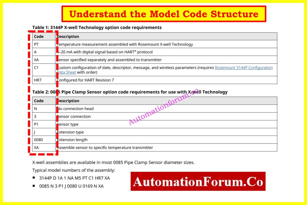
Model codes specify exactly how the transmitter is built.
For example:
3144P D1 A 2 I5 M5 PT XA C1 HR7
Breakdown:
- 3144P: Model series
- D1: Aluminum dual-compartment housing
- A: 4-20 mA HART output
- 2: Dual sensor input
- I5: Intrinsically safe approval (USA)
- M5: LCD display
- PT: X-well Technology
- XA: Assembled with sensor
- C1: Custom configuration
- HR7: HART revision 7
When ordering, this model code ensures you receive exactly what you need.
Thermocouple Calibration: Step-by-Step Guide: Thermocouple Calibration Procedure
Step 4. Verify Input and Output Capabilities
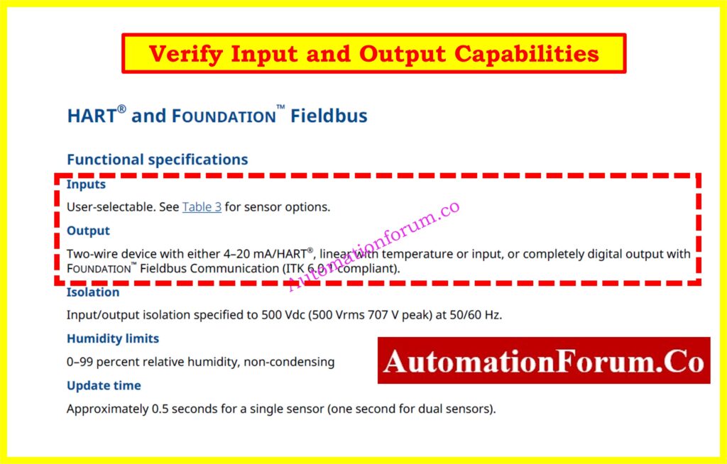
Input Support:
- RTDs (Pt100, Pt1000, etc.)
- Thermocouples (types J, K, T, etc.)
- Millivolt and resistance inputs
Output Protocols:
Choose HART for compatibility with most PLCs and DCSs, or Fieldbus for smart diagnostics and digital communication in advanced systems.
Step 5. Accuracy and Stability
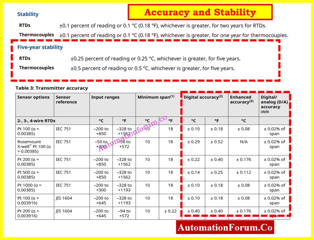
For RTDs (Pt100, IEC 751):
- Standard Digital Accuracy: ±0.10 °C
- Enhanced (P8 Option): ±0.08 °C
- D/A Conversion Accuracy: ±0.02% of span
For Thermocouples:
- Accuracy ranges from ±0.25 to ±0.75 °C depending on type
Long-Term Stability:
- RTDs: ±0.1 °C over 2 years
- Enhanced option: ±0.25 °C over 5 years
Tip: Use transmitter-sensor matching (Option C2) to further improve measurement accuracy.
RTD Transmitter Calibration Made Easy: Calibration Procedure for RTD Temperature Transmitter
Step 6. Safety Certifications and Compliance
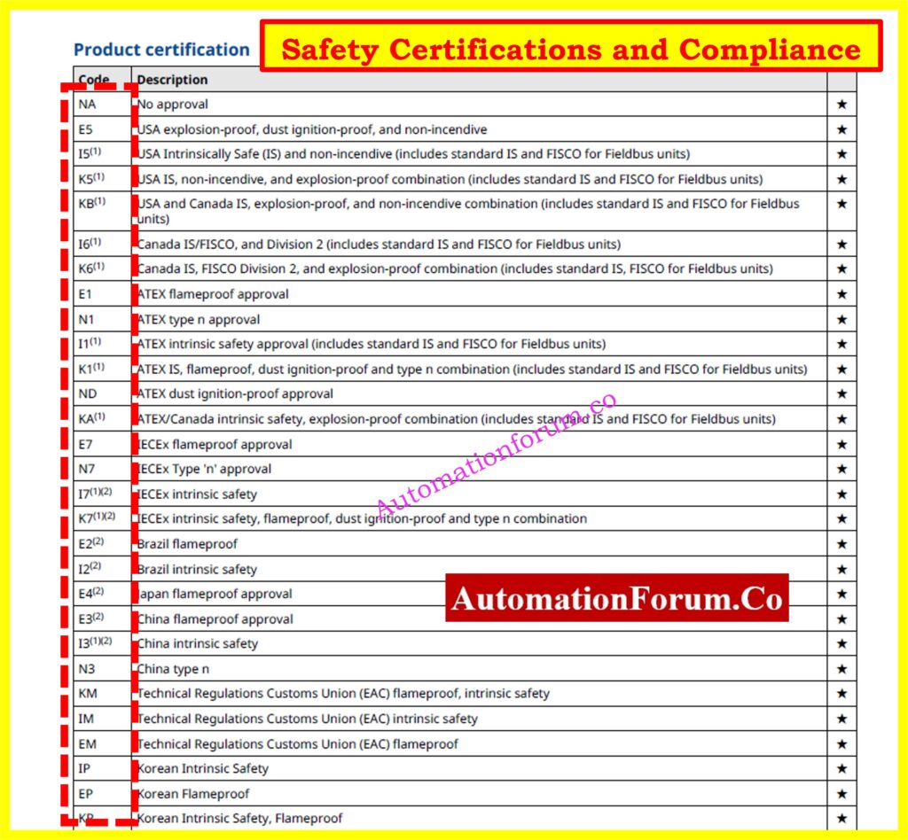
Depending on your site requirements, the transmitter may need to meet certain safety standards.
The 3144P supports:
- Intrinsically safe, explosion-proof, and non-incendive certifications: ATEX, IECEx, FM, CSA, EAC
- Functional Safety (SIL 2/3) compliance as per IEC 61508
- Custom NAMUR fail-safe current settings for fault conditions
Always choose the correct certification code (e.g., I5, K5, E1) based on the intended installation area.
Step 7. Installation Friendly Features
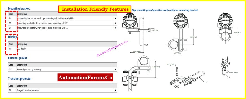
The Rosemount 3144P includes several features to make field installation easier:
- Dual-compartment housing protects electronics from moisture
- Optional LCD display (M5) for local monitoring
- Multiple conduit entry types: NPT, M20, PG13.5, JIS
- Mounting kits for pipe or panel mounting
- Smart functions like Hot Backup™, Drift Alerts, and Fail-Safe Modes
When replacing an older unit, verify mounting and housing to ensure compatibility.
Thermocouple or RTD? Choose Smartly: Choosing Between Thermocouples and RTDs: A Practical Guide for Temperature Sensing
Step 8. Diagnostic and Redundancy Options
Advanced diagnostics include:
- Sensor Drift Alert: Detects when sensors go out of spec
- Hot Backup™: Automatically switches to secondary sensor upon failure
- Min/Max Logging: Captures process extremes
- Loop Integrity Monitoring: Especially for thermocouples
Custom dual-input configurations:
- U1: Hot Backup
- U2/U3: Average temperature + Drift Alerts (Warning/Alarm)
- U4: Independent inputs
- U5: Differential temperature
- U6: Average only
These features are useful for critical processes, safety loops, or when using redundant sensing.
What Happens During Transmitter Burnout: Burnout Function of a Temperature Transmitter with an example
Step 9. Environmental Ratings and Limits
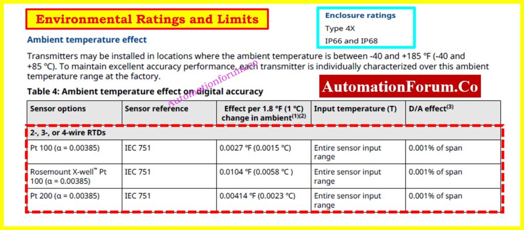
Know the environmental limits before installation:
- Ambient Operating Temperature: -40 to +85 °C
- Storage Temperature: -60 to +121 °C
- Ingress Protection: IP66/IP68, Type 4X
- Vibration Resistance: 3 g from 60 to 2000 Hz
Use stainless steel housing (Options D5-D8) for corrosive or offshore environments.
Step 10. Wiring, Loop, and Display Configuration
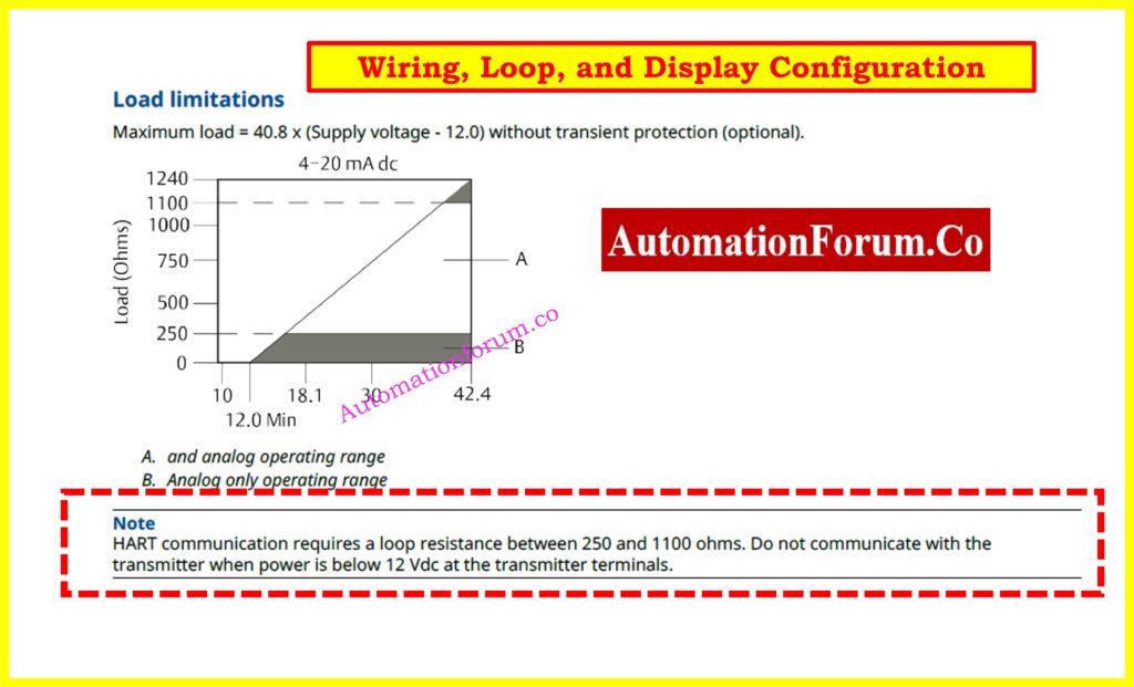
HART Loop Requirements:
- Loop resistance: 250-1100 ohms
- Supply voltage: 12 to 42.4 VDC
Display (M5 Option):
- Shows temperature (°C/°F), mA output, sensor values
- Configurable messages and bar graphs
Use a Field Communicator or AMS Device Manager for configuration or diagnostics.
RTD Calibration: Easy How-To Guide: RTD Calibration Procedure
Step 11. Rosemount X-well™ Technology
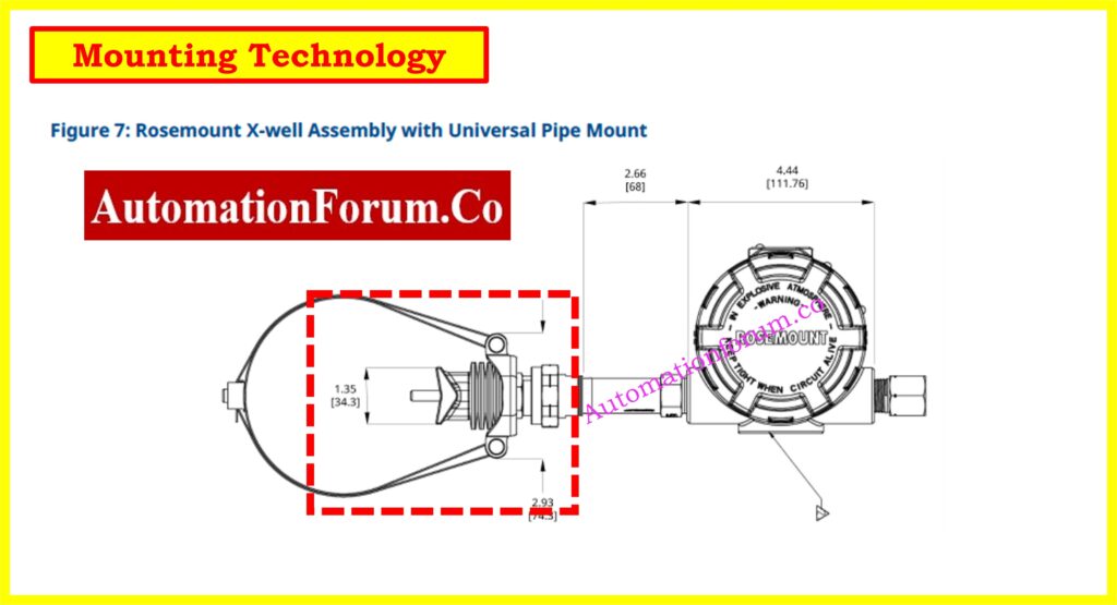
For applications where process penetration is not allowed:
- X-well Technology calculates process temperature from surface and ambient readings
- No need for a thermowell or insertion sensor
- Ideal for small pipes or corrosive/high-pressure lines
- Requires clamp-on sensor (e.g., Rosemount 0085)
X-well reduces installation time and increases safety.
Refer the the below link for the Collection of Temperature Measurement Calculators
Step 12. Calibration, Testing, and Documentation Options
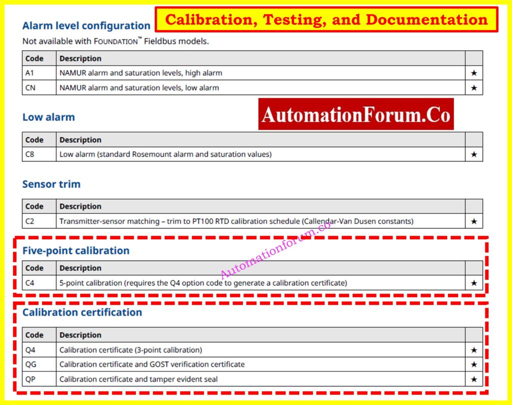
Common options:
- Q4: 3-point calibration certificate
- C4: 5-point calibration
- QT: Functional Safety Certification
- QG: GOST compliance and calibration cert
- QP: Tamper-evident seal
Check calibration records when replacing an instrument to ensure accuracy and consistency.
How to Calibrate Temperature Instruments: Temperature Calibration Procedure
Step 13. Replacing an Existing Transmitter
When a transmitter fails or needs to be upgraded, replacement should be done with attention to compatibility and long-term performance. A few proactive steps will make the process efficient and reliable.
Match input/output types and sensor wiring
Ensure the new transmitter accepts the same type of input as the existing one whether RTD (e.g., Pt100, Pt1000) or thermocouple (e.g., Type J, K, T). Also, confirm whether it is a single-sensor or dual-sensor input. Check wiring types 3-wire, 4-wire for RTDs, or shielded pairs for thermocouples. Incorrect wiring leads to erratic readings or communication failures.
Find 4-20mA Output Fast: How to Calculate Temperature Transmitter 4-20mA Output Using Linear Equation and Percentage Method ?
Order the correct housing and conduit configuration
Housing type affects environmental protection and installation fit. If the original transmitter had an aluminum dual-compartment housing with NPT threads, the replacement should match exactly unless upgrades are planned. Mismatched threads (e.g., NPT vs. M20) can delay installation or require costly adapters.
Thermocouple Transmitter Calibration Guide: Calibration Procedure for Temperature Transmitter – Thermocouple
Confirm supply voltage and loop resistance
For HART transmitters, check that the loop power supply provides at least 12 VDC at the transmitter terminals after accounting for cable resistance and a minimum 250-ohm resistor for HART communication. Insufficient voltage will result in startup failures or loss of communication.
Consider upgrades like Hot Backup™ and local display
Take advantage of features not available in older models. Adding a local display (M5 option) provides immediate diagnostics, especially useful during commissioning. Redundancy options like Hot Backup™ help maintain continuous operation by switching sensors if the primary fails.
Use old model code or serial number to avoid errors
Locate the nameplate on the existing unit and copy down the full model code and serial number. This allows vendors or internal stores to provide an exact or functionally equivalent replacement without guesswork.
Scan the QR code for digital specs
Newer Rosemount transmitters feature QR codes that link directly to device-specific configuration, manuals, and datasheets. Use this feature on-site to verify compatibility and speed up troubleshooting or installation validation.
Step 14. Using the Datasheet in Project Design
In capital projects or plant expansions, the datasheet serves as a blueprint for selecting and configuring transmitters that meet the project’s process, safety, and regulatory needs.
Use model codes to create accurate BOMs
Model codes define every functional and mechanical aspect of a transmitter. During project planning, using datasheet model code tables helps generate a complete and error-free bill of materials. Each digit or option in the model code reflects features like housing material, output protocol, approvals, and display.
Ensure certification compliance with plant standards
Datasheets list all available certifications (e.g., ATEX, IECEx, FM, CSA). For hazardous areas or SIL-rated applications, select the right combination of intrinsic safety, flameproof, or functional safety certifications. Coordination with plant safety teams ensures compliance from the start.
Coordinate sensor and accessory choices
The transmitter is just one part of the temperature measurement loop. You also need compatible sensors (e.g., Pt100 RTDs or thermocouples), thermowells, clamps, or extension cables. The datasheet ensures all components are compatible in terms of sensor type, range, response time, and electrical characteristics.
Use Option C1 for factory pre-configuration
To save commissioning time, specify Option C1 to receive transmitters with preset configurations such as sensor type, range, fail-safe setting, and output scaling. This is especially helpful for large projects with multiple units where consistency matters.
Select mounting kits appropriate for the site layout
Mounting style (pipe-mount, panel-mount, DIN-rail) and the availability of brackets or clamps can be confirmed in the datasheet. Choosing the right accessories in advance ensures seamless field installation and reduces delays.
Avoid field rework and installation delays
A well-read datasheet enables coordination between engineering, procurement, and installation teams. This avoids surprises on-site like incompatible housings, incorrect sensor wiring, or non-compliant certifications.
Step 15. Final Checklist when Reading a Datasheet
Use this final checklist before finalizing your selection, especially when specifying transmitters for procurement, installation, or maintenance replacement:
- Model Code matches your spec?
Does the full code reflect the correct housing, display, protocol, and options for your application? - Output Protocol (HART or Fieldbus)?
Ensure compatibility with your control system HART is more common with analog systems, while FOUNDATION Fieldbus suits digital networks. - Sensor Input type correct?
Match the transmitter input with the sensor type RTD (Pt100, Pt1000), thermocouple (J, K, etc.), or ohm/mV input. - Mounting and housing match field conditions?
Check dimensions, thread type, material (aluminum or stainless steel), and environmental rating. - Safety Certifications required?
Confirm certifications like ATEX, FM, IECEx, CSA, or SIL for use in hazardous areas or safety-instrumented systems. - Display needed for local monitoring?
Decide if you need a local LCD for real-time temperature and diagnostics or just remote monitoring. - Diagnostics or redundancy needed?
Enable features like sensor drift alerts, Hot Backup™, and min/max logging if your application needs high reliability. - Calibration documentation required?
Do you need a 3-point (Q4) or 5-point (C4) calibration certificate for quality systems or audits? - Environmental limits within site conditions?
Confirm ambient and storage temperature ranges, IP ratings, and vibration specs are suitable for your installation area. - Replaces old unit directly?
Ensure the new unit physically and functionally replaces the old one check dimensions, wiring, output, and sensor compatibility.
Step 16. Practical Insights for Maintenance and Troubleshooting
The datasheet is a powerful tool for field maintenance too:
- Use sensor type and range info to isolate faults
- Confirm supply voltage and loop specs during troubleshooting
- Check built-in diagnostics like drift alerts or fail-safe behavior
- Use the standard configuration section to reset to default settings quickly
When transmitters are swapped in the field, this information helps ensure the replacement behaves as expected without needing to connect a communicator.
Convert mV to Temperature Easily: How to Convert Thermocouple Millivolts to Temperature: A Step-by-Step Guide
Step 17. Vendor Coordination and Documentation
When working with suppliers or OEMs:
- Use the datasheet to align specifications across multiple vendors
- Reference model code options in RFQs
- Confirm communication protocol revisions (e.g., HART Rev 5 or 7)
- Include factory configuration (C1), calibration (Q4), or labeling (QP) in your order
- Refer to datasheet accessory listings for mounting hardware, adapters, and displays
This streamlines procurement, commissioning, and integration efforts.
Reading and understanding a temperature transmitter datasheet like that of the Rosemount 3144P is an essential skill. It helps avoid miscommunication, supports system reliability, and ensures accurate installation and commissioning. Whether you’re replacing a failed transmitter or specifying devices for a new plant, taking time to read the datasheet pays off in fewer errors, better performance, and longer service life.
If in doubt, collaborate with your instrument vendor or system integrator. And always refer back to the datasheet it’s more than just a document; it’s your best planning tool.
Example: Rosemount 3144P Temperature Transmitter Datasheet
For detailed example specifications, certifications, and configuration options, download the official datasheet for the Rosemount 3144P temperature transmitter.
Frequently Asked Questions (FAQs)
Why is reading a temperature transmitter datasheet important?
Reading the datasheet makes sure that the transmitter you choose has the right input type, output protocol, safety certifications, environmental ratings, and mounting style for your process. It helps avoid expensive mistakes, delays, and problems with following the rules when installing or replacing something.
What is the most critical section to look at when selecting a transmitter?
The model code structure part is the most important since it tells you everything about the transmitter’s setup, including its housing, communication type (HART or Fieldbus), sensor input type, display choice, and certifications. If anything doesn’t match up here, it could cause problems with installation or operation.
What is Hot Backup™ and how is it useful?
The Rosemount 3144P has a redundancy function called Hot Backup™ that automatically changes from the main sensor to a backup sensor if the first one fails. This makes sure that measurements may be taken without interruption in important situations and makes things more reliable.
Can I use a Rosemount 3144P without a thermowell?
Yes. The 3144P can accurately measure process temperature from surface and ambient conditions utilizing a clamp-on sensor and Rosemount X-well™ Technology. This means that thermowell insertion is not necessary.
What safety certifications should I look for?
It depends on where you are going to install it. ATEX, IECEx, FM, CSA, and SIL (2 or 3) are some of the most common certifications. Always check the categorization of your location (for example, hazardous area) and pick a transmitter that fits, using the right approved option codes like I5, K5, or E1.
How do I confirm loop and power requirements for a HART transmitter?
The datasheet says that a 3144P HART device that uses 4-20 mA needs:
- Supply voltage: 12-42.4 VDC
- Loop resistance: 250-1100 ohms
For correct digital communication and analog signal transfer, certain parameters must be met.
How can I avoid ordering the wrong transmitter replacement?
Look at the nameplate on the current device to find the model code and serial number. This makes sure you get a replacement with the identical settings. You can also scan the QR code on newer units to get all the settings information right away.