- Differential Temperature Measurement
- Cold Junction Compensation – CJC
- Techniques for Reference Junction Compensation
- Reference Diagram – Why Thermocouple Reference Junction Compensation Required ?
- Example of Cold Junction Compensation
- Advantages of Thermocouples Despite Compensation Needs
- FAQ on Cold Junction Compensation (CJC) in Thermocouples
- What is Cold Junction Compensation (CJC)?
- What happens if you don’t perform Cold Junction Compensation in a thermocouple circuit?
- What is the Cold Junction Compensation bridge in a thermocouple?
- What is Reference Junction Compensation?
- Why do we need Cold Junction Compensation?
- Where is the Cold Junction of a Thermocouple?
- What are the Two Junctions of a Thermocouple?
- Test Your Knowledge on Thermocouple
A thermocouple utilizes Seebeck’s Effect to produce a voltage measuring technique discovered by Thomas Seebeck in the 1800s. Two dissimilar metals connected in a circuit with temperature junctions produce a steady electrical current according to his discovery. Thermal energy activates hot junction electrons and produces a voltage difference which pushes electrical current from hot to cold junctions.
A hollow tube serves as the basis to understand this concept by demonstrating pressure differences at its two ends. Nature drives the movement of air through pressure differential so that it follows the path from higher pressure to lower pressure. Electron movement behaves similarly in thermocouple devices since heated junction electrons behave at high pressure velocity but cold junction electrons behave at low pressure velocity. The voltage output increases in direct proportion to the difference between hot and cold junction temperatures.
Differential Temperature Measurement
A thermocouple measures the temperature difference between its two junctions rather than the absolute temperature at the hot end. To determine the actual temperature at the hot junction, both the voltage produced and the temperature at the cold junction must be known.
In past laboratory use an ice bath (0°C/32°F) was used to keep the cold junction at a stable reference. Scientists developed thermocouple voltage tables by using the ice bath reference allowing them to calculate hot junction temperatures accurately. The thermocouple voltage was transmitted through copper wires to a measuring instrument that utilized tables for temperature calculations.
Cold Junction Compensation – CJC
Modern thermocouples replace the ice bath with cold junction compensation (CJC), an electronic method to adjust the voltage as if the cold junction were at 0°C. The connection point where the thermocouple meets the measuring device is called the cold junction. The location of this junction at temperatures other than 0°C produces measurement results that deviate from standard thermocouple table values.
The correction process uses a precision RTD (Resistance Temperature Detector) or thermistor to calculate the real temperature at the cold junction. The system compares measured voltage to calculate the voltage output from the thermocouple when the reference junction maintains a temperature of zero degrees Celsius. The adjustment process enables measured voltage readings to match the thermocouple tables precisely for accurate temperature detection.
Techniques for Reference Junction Compensation
The control of reference junction temperature operates through several existing management techniques.:
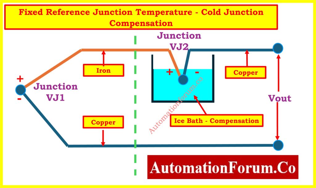
Fixed Reference Junction Temperature
Stabilizing the reference junction has the purpose of maintaining a constant temperature to ensure stable voltage measurement. This was historically done using an ice bath, as the water-ice mixture maintains a stable temperature due to water’s latent heat of fusion.
Some early designs included a mercury bulb thermometer with a platinum wire loop. As the reference junction temperature increased, the mercury level rose, adjusting the resistance and compensating for voltage variations.
Another design used a bi-metallic spring to shift the needle of an analog meter, automatically adjusting for temperature changes at the reference junction.
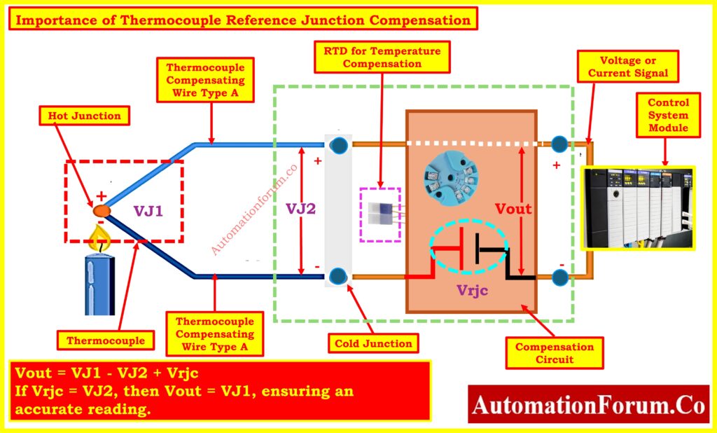
Electronic Compensation Circuits
A modern and practical approach is to include an additional compensating voltage source in the thermocouple circuit. This voltage source is equal in magnitude but opposite in polarity to the reference junction voltage.
A thermistor or RTD measures the temperature at the cold junction, generating a compensating voltage (Vrjc). This voltage cancels out the reference junction’s voltage, ensuring that the output voltage (Vout) only detects the voltage from the hot junction.
Mathematically:
Vout = VJ1 – VJ2 + Vrjc
The measurement becomes accurate when Vrjc equals VJ2 because Vout receives an equivalent value VJ1.
Reference Diagram – Why Thermocouple Reference Junction Compensation Required ?
The illustration below explains the vital role of thermocouple reference junction compensation through visual representation:
Example of Cold Junction Compensation
When a type J thermocouple detects 570°F temperature it produces 16.266 mV. A cold junction at 69°F generates a voltage that opposes the measurement since it produces 1.048 mV. Under such circumstances the output voltage meter would display 15.218 mV only. An added compensation circuit producing 1.048 mV generates the correct VJ1 voltage of 16.266 mV at the thermocouple tables for accurate temperature measurement.
Must read: Learn the methods and examples for converting thermocouple millivolts to temperature. Click here!
When using a Type K thermocouple to measure 1000°F temperature it produces VJ1 = 41.276 mV. The uncompensated reading will be 38.249 mV when both junctions have different temperatures where VJ1 equals 41.276 mV and VJ2 equals 3.027 mV. An external compensation circuit designed to produce Vrjc = 3.027 mV transforms an initial imperfect reading of 41.276 mV into the precise temperature value.
Need to calibrate a thermocouple? Find out how with our step-by-step guide. Click here!
Advantages of Thermocouples Despite Compensation Needs
When considering compensation it might seem logical to replace thermocouples with RTD or thermistor devices. However, thermocouples provide key advantages:
- The operating temperature range of thermocouples extends substantially beyond what RTDs or thermistors can tolerate.
- Thermocouples demonstrate excellent durability by working well in challenging environmental settings.
- Thermocouples possess quick temperature response capability that enables their utilization in fluid systems requiring rapid measurement.
- The cost of thermocouples remains lower than that of RTDs or thermistors while monitoring high-temperature conditions.
- Thermocouples present diversified options since manufacturers make them available in different versions (Type K, J, T, etc.) that match various environmental conditions as well as precision requirements.
The implementation of cold junction compensation remains essential for achieving accurate thermocouple temperature readings. The reference junction temperature correction enables thermocouple measurements to conform to standard voltage-temperature tables. Industrial applications prefer thermocouples as widespread temperature sensors because they combine robustness along with a wide operational range and affordability despite precise measurement challenges from thermistors and RTDs. Cold junction compensation knowledge maintains thermocouples as dependable temperature monitoring tools for different industrial applications.
Must read: A detailed checklist for troubleshooting thermocouples. Click here!
FAQ on Cold Junction Compensation (CJC) in Thermocouples
What is Cold Junction Compensation (CJC)?
Cold Junction Compensation (CJC) represents the temperature-compensating process of thermocouple measurements referring to the reference junction. The thermocouple depends on hot and cold junction temperature differences to measure conditions so CJC acts to correct cold junction temperatures for accurate hot junction readings.
What happens if you don’t perform Cold Junction Compensation in a thermocouple circuit?
What is the Cold Junction Compensation bridge in a thermocouple?
The Cold Junction Compensation bridge operates as a circuit designed to manage temperature differences between the cold junction points. A stable DC power source such as a mercury battery supplies the device and the output voltage adjusts depending on the difference in temperatures between the cold junction and the established reference point at 0°C or 32°F. The thermocouple achieves precise temperature measurement through this compensation method which adjusts for temperature fluctuations at the cold junction.
What is Reference Junction Compensation?
Reference Junction Compensation is the process of compensating for the temperature at the thermocouple’s reference junction (the cold junction). The temperature at the reference junction must be known to accurately measure the temperature at the hot junction. Traditional cold junction temperature control utilized ice-filled baths while modern systems employ electronic methods for compensation.
Why do we need Cold Junction Compensation?
Thermocouple performance needs Cold Junction Compensation since its reference point thermocouple does not stay at a predetermined temperature (0°C or 32°F). The inability to compensate the thermoelectric voltage would result in non-matching temperatures between the hot junction and the actual measurement values. The electronics use CJC to correct measures for real cold junction temperature variations which produces precise hot junction readings.
Where is the Cold Junction of a Thermocouple?
Thermocouple cold junctions exist where dissimilar metal wires join together at room temperature or chosen reference points. The instrument section contains the cold junction which functions as the opposite point to the hot junction measurement location.
What are the Two Junctions of a Thermocouple?
A thermocouple utilizes two distinct metallic wires that form connection points at both ends. A thermocouple contains a “hot” junction responsible for the temperature measurement. The “cold” junction or reference junction maintains its temperature at a constant value. A temperature measurement happens through the voltage difference created between these two junction points.
Test Your Knowledge on Thermocouple
Whether you are an instrumentation engineer or a student, this MCQ will help you measure your understanding of thermocouples, including the Seebeck effect, temperature ranges, junction types, and their practical uses in industrial settings. Each question is carefully prepared to cover key concepts such as thermoelectric effects, material compatibility, and common standards